Note: Descriptions are shown in the official language in which they were submitted.
CA 02418886 2003-02-12
HOf,O 1146 PC:A
REFLECTOR/REFRACTOR LIGHT CONTROL LUMINAIRE
BACKGROUND OF THE INVENTION
The invention relates generally to reflector/refractor luminaire globe
combinations and
particularly to such combinations exhibiting increased utilization of light
generated by
controlling the angles of incidence of light rays incident on a refractor
section of such a
combination.
Reflector/refractor devices have long been available in the art and utilizable
with a variety
of Tamping configurations to provide light distribution characteristics
suitable for a number of
lighting applications. Such reflector/refractor combinations have typically
been formed of light
transmissive materials such as glass, plastic materials such as acrylics, etc.
Prisms and similar
light altering structures are typically formed on both interior and exterior
surfaces of prior
reflector/refractor combinations in order to direct light from a contained
lamp in a manner
providing a desired level of light within a space that is to be illuminated.
Reflector/refractor
combinations are disclosed in a number of issued United States patents
including United States
Patent 4,839,781 to Barnes et al, this patent disclosing the provision of a
series of sectional zones
on a reflector/refractor for reflecting and refracting light. The sectional
zones of the Barnes et al
reflector/refractor have formed thereon prisms having reflective, refractive
or either reflective
and refractive characteristics depending upon location relative to a light
source, the
rcflective/refractive prisms and similar elements acting in combination to
vary light distribution.
The Barnes et al reflector/refractor, while formable from either glass or
acrylic materials, for
example, is preferably formed of light transmissive synthetic resin materials,
such as, for
example, an acrylic UVAS or similar material such as by injection molding.
Fouke, in United States Patent 6,027,231, discloses a reflector/refractor
combination
having prisms of varying kind disposed on surfaces thereof for a desired
control of light
CA 02418886 2003-02-12
generated within the interior of the combination by means of an HID lighting
source. While the
reflector/refractor of Fouke can be formed of either glass or plastic
materials such as acrylic, the
optical structure of Fouke is preferably formed of glass and the HID light
source may constitute
either a mercury, metal halide, or high pressure sodium lamp inter alia. Fouke
also discloses
prisms of differing configuration and kind useful in directing light in a
desired direction.
In United States Patent 563,836, Blondel et al disclose a variety of
configurations of lamp
globes that are essentially reflector/refractor combinations, these lamp
globes having differing
arrangements of prisms, flutes and other light reflecting and/or refracting
capabilities, the
"globes, shades, reflectors, and other envelops" of Blondel et al being
preferably formed of glass
or similar light transmissive material. The prisms formed on the Blondel et al
globes take a
variey of forn~s having differing structure and light reflective and/or
refractive capabilities
chosen for use in particular situations for directing light in a desired
direction.
Osteen, in United States Patents 4,118,763 and 5,036,445, describes light
transmissive
globes used in luminaires and having prisms of differing description formed on
said globes for
controlling light direction and utilization. Harling, in United States Patent
3,329,812, discloses a
refractor arrangement having prismatic structures capable of directing light
in a desired direction.
Kelly et al, in United States Patent 5,434,765, discloses a
reflector/refractor combination
intended to direct light downwardly by means of a judicious disposition of
prismatic structures
formed on said combination for the purpose of light control.
The body of art developed in the lighting field as represented by the patents
described
above and by numbers of other patents as well as countless luminaires
available in the
marketplace over time have usually attempted to more efficiently utilize light
generated by a light
source contained, enclosed or otherwise associated with a light transmissive
globe member
forming the optical portion of luminaires configured according to the prior
art. The present
invention further intends improvement in the control of light within such
globe members by
2
CA 02418886 2003-02-12
directing light incident on major portions of a reflector section of such a
globe member to a point
or loci of points preferably located immediately above a light source such
that the pattern of that
light incident on the reflector section and onto an associated refractor
section is similar to that
light directly incident on the refractor section and emanating from the light
source itself.
Improved lighting control thus obtains to provide increased efficiency of
light generated by the
light source as well as a desired distribution of light from the luminaire.
The invention provides a light transmissive globe member having a reflector
section and a
refractor section enclosing a tight source such as a gaseous discharge lamp
and particularly a
high intensity discharge (HID) lamp. Light produced by the light source
emanates outwardly
thereof from within the interior of the globe member toward essentially all
surfaces of the globe
member. That portion of the generated light emanating from lower, central and
upper portions of
the light source have a similar pattern of incidence on the refractor section
of the present globe
member. Major portions of the light emanating from the light source and
incident on the
reflector section, that is, at least over major portions of said reflector
section, is incident on
refractive prisms formed on interior surfaces of said reflector section and is
refracted toward
reflective prisms formed on outer surfaces of said reflector section. Light
rays thereby incident
on the reflective prisms are reflected back through the refractive prisms
formed on inner surfaces
of the reflector section and are refracted through a focal point or loci of
points directly above the
light source such that at least major portions of the light thus redirected
from the reflector section
is incident on at least major portions of the surfaces of the refractor
section in a pattern similar to
the patterns of that light emanating directly from the different portions of
the light source and
into direct contact with surfaces of the refractor section. By virtue of the
similarity of angles of
incidence of both direct light and redirected light onto refractor section
surfaces, light emanating
from the globe member of the invention can be more readily controlled for
direction into space
CA 02418886 2003-02-12
externally of the globe member to thereby increase the efficiency of light
utilization generated by
the light source.
It is therefore an object of the invention to provide a light transmissive
globe member
useful in a luminaire and having a reflector section functioning in
combination with a refractor
section so that light generated by a light source within the globe member and
incident on the
reflector section is redirected to form a pattern similar to light patterns of
that light directly
incident on the refractor section and emanating directly from the light
source.
It is another object of the invention to provide a globe member formed of
light
transmissive material and useful in a luminaire for control of light generated
by a light source
contained within said globe member, the globe member being formed of a
reflector section and a
refractor section and functioning to control light direction by the reflection
and refraction of light
incident on the reflector section and emanating from the light source to a
point or loci of points
preferably located immediately above the light source such that a pattern
ofredirected light
incident on at least portions of the refractor section is similar to patterns
of light emanating from
varying portions of the light source directly onto at least portions of the
refractor section, thereby
permitting control of light distribution and improvement of light utilization.
It is a further object of the invention to provide a globe member formed of
light
transmissive material for use in a luminaire for light control and having a
reflector section and a
retractor section cooperating to control light directed from the globe member,
the reflector
section and the refractor section being respectively formed with
reflective/refractive prisms and
refractive prisms on exterior surfaces thereof and configured to redirect
light incident on at least
major portions of the reflector section back into the interior of the globe
member and through a
focal point or loci of points and into incidence with at least major surface
portions of the refractor
section in a pattern similar to patterns of light emanating from differing
portions of the light
4
CA 02418886 2003-02-12
source and directly incident on said refractor section surfaces, thereby to
control light distribution
and improve lighting efficiency.
Further objects and advantages of the invention will become more readily
apparent in
light of the following detailed description of the preferred embodiments.
FIGI1RE 1 is a schematic view representational of a light transmissive globe
member
forming a portion of a luminaire and illustrating a ray trace incident on
portions of a refractor
section of the globe member and emanating from a lower portion of a light
source;
FIGURE 2 is a schematic view representational of the globe member of Figure 1
and
illustrating a pattern of light similar to the pattern of light shown in
Figure 1 but emanating from
a central portion of the light source;
FIGI1RE 3 is a schematic view representational of a ray trace such as is shown
in Figures
1 and 2 but emanating from an upper portion of the light source;
FIGURE 4 is a schematic view representational of a ray trace from a central
portion of a
light source onto at least major portions of a reflector section of a globe
member configured as a
portion of a luminaire;
FIGURE 5 is a schematic view representational of a ray trace emanating from
the light
source both to major surface portions of the reflector section of the globe
member and directly
onto the refractor section from a top portion of the light source;
FIGURE 6 is an enlarged schematic illustrating incident and reflective rays
contacted and
being directed from a portion of the reflector section of the globe member;
FIGURE 7 is a detailed schematic illustrating light rays as shown relative to
Figure 6;
FIGURE 8 is a schematic illustrating refraction of light incident on the
refractor section
of the globe member externally of said globe member;
FIGURE 9 is a detailed schematic illustrating the configurations of refractive
prisms
formed on exterior surfaces of the refractor section of Figure I ;
CA 02418886 2005-05-30
FIGURE 10 is a table detailing the characteristics of the refractive prisms
illustrated in
Figure 9;
FIGURE 1 I is a detailed schematic illustrating the configurations of
re&active prisms
formed on interior surfaces of a preferred embodiment of the refractor section
of Figure 1;
FIGURE 12 is a table detailing the characteristics of the refractive prisms
illustrated in
Figure 1 I ;
FIGURE 13 is a detailed schematic illustrating the configuration of reflective
prisms
formed on exterior surfaces of a preferred embodiment of the refractor section
of Figure 1;
FIGURE 14 is an elevational view of a globe member of a particular shape and
constituting another embodiment of the invention;
FIGURE 15 is an elevational view of a globe member shaped according to a
further
embodiment;
FIGURE 16 is an elevational view of a globe member shaped according to yet
another
embodiment of the invention;
FIGURE 17 is an elevational view of a globe member shaped according to another
embodiment of the invention;
FIGURE 18 is a schematic illustrating a further embodiment of the invention;
FIGURE 19 is a schematic view illustrating yet another embodiment of the
invention;
and,
FIGURE 20 is a schematic view illustrating a still further embodiment of the
invention.
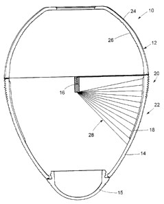
Referring now to the drawings and particularly to Figures 1 through 3, a globe
member 10
is seen to be comprised of a reflector section 12 and a refractor section 14,
the sections 12, 14
being joined together either in a conventional fashion as desired or in a
novel manner such as is
described in co-pending Canadian patent application Serial No. 2,418,766,
entitled "Luminaire
Globe Having Low Glare Bandless Seam", filed of even date and assigned to the
present
6
CA 02418886 2005-05-30
assignee. The globe member 10 is completed by the attachment of door 15 to an
open end of the
refractor section 14, the provision of a door and an attachment therefor to
the suction l4
conveniently being conventional in nature. The globe member 10 is provided
with a light source
16 substantially disposed centrally within the confines of the globe member
10, an upper end of
the light source 16 being essentially disposed substantially at a level within
the globe member l0
such that an upper portion of an arc tube of the light source 1 ti is
essentially coincident with a
plane of interconnection between said sections 12, 14. It is to be understood
that the sections 12,
14 can be formed of glass and/or plastic materials such as acrylic in a
conventional manner.
!~urther, it is to be understood that the light source 16 typically comprises
a gaseous discharge,
fluorescent or incandescent lamp inter alia and preferably a high intensity
discharge (H1D) lamp,
the representation of the light source 16 as seen in the drawings being
essentially schematically
shown for ease of illustration.
The refractor section 14 is seen to be provided with interior prisms 18 and
with exteriorly formed
prisms 20 and 22, the prisms 20 being preferably taken to 6o splitter prisms
as are described in copending
Canadian patent application Serial No. 2,418,763 entitled "Prismatic
Structures having Shaped Surfaces",
filed of even date and assigned to the present assignee. The prisms 20, 22 ate
refractive prisms and act to
direct light incident thereon exteraal(y of the globe member 10 as will be
described in more detail
hereinafter. The prisms 18 can conveniently take the form of prisms as are
shown in the Hlondel patent,
the prisms 18 acting to spread light laterally.
The reflector section 12 is seen to be formed with reflective prisms 24 formed
on at least
major portions of exterior surfaces thereof, said reflective prisms 24
functioning to reflect at least
major portions of light incident thereon back into the interior of the globe
member 10 and into
incidence on refractive prisms 26 fotlrted over major portions of interior
surfaces of the section
l2. The prisms 24, 26 are particularly configured for control of light within
the globe member l0
7
CA 02418886 2003-02-12
as will be described in detail hereinafter. The prisms 24 can be formed as
90° prisms or angles
thereabout that angular value as shown in Figure 13.
Figure 1 is particularly seen to show a pattern of light represented by light
rays 28
emanating from a bottom portion of the arc tube of the light source I 6. The
rays 28 essentially
impinge on the refractor section 14 at certain angles of incidence dependent
upon the location of
the light source 16 and on the downward and inward curvature of body portions
of the refractor
section 14. The prisms 20 and 22 act to refract the light rays 28 exteriorly
of the globe member
as is best shown in Figure 8 as will be described in detail hereinafter.
Referring to Figure 2, tight rays 30 are seen to emanate from a central
portion of an arc
tube of the light source 16, the pattern fornned by the light rays 30
essentially being incident on
surfaces of the refractor section 16 at incidence angles similar to the
incidence angles of the light
rays 28 shown in Figure 1 which emanate from bottom portions of the light
source 16.
Referring further to Figure 3, light rays 32 are seen to emanate from a
topmost portion of
an arc tube of the light source I6 and to be incident on surfaces of the
refractor section 14 in a
pattern similar to the patterns of the light rays 28 and 30 as respectively
illustrated in Figures 1
and 2, the angles of incidence of the light rays 32 being similar to the
angles of incidence of the
light rays 28 and 30. Essentially, Figures 1 through 3 illustrate the fact
that light rays emanating
from the light source 16 throughout its virtual height have similar angles of
incidence on surfaces
of the refractor section 14 depending upon location on said surfaces of the
refractor section 14.
Referring now to Figure 4, the globe member 10 is illustrated for simplicity
without exact
representation of a light source such as the light source 16 of Figures 1
through 3, an effective
center of an arc tube of a virtual light source being represented at 34 with
light rays 36 being
represented as emanating from 34 to be incident on the refractive prisms 26,
the light rays 36
being refracted by the refractive prisms 26 and then passing through wall
portions of the reflector
section l2 into incidence with the reflective prisms 24. Figures 6 and 7 show
in respectively
8
CA 02418886 2003-02-12
greater detail the structure ofthe refractive prisms 26 as well as the
refraction ofthe light rays 36
to become light rays 38 which are incident on the reflective prisms 24. After
reflection in a
known manner by the reflective prisms 24, the light rays are represented at 40
and are incident on
the refractive prisms 26. The refractive prisms 26 refract the light rays 40
to produce light rays
42. the light rays 42 being redirected as is shown in Figure 4 into the
interior of the globe
member 10 and through a focal point at 44, the focal point 44 being
essentially a loci of points in
practical terms, this focal point 44 being disposed immediately above the
light source such as is
represented by the light source 16 of Figures 1 through 3 and in preferred
embodiments lying on
a longitudinal axis of the globe member 10. The focal point 44 is conveniently
taken to be
approximately 0.25 inch above a tamp arc tube of a light source such as the
light source 16, this
redirecting of light rays from central portions of a light source as
represented at 34 back above
the light source causes the refracted light rays 42 to be incident on surfaces
of the refractor
section 14 in a pattern similar to that formed by the light rays 20, 30 and 32
referred to
hereinabove relative to Figures I through 3, that is, the pattern of light
rays emanating directly
from the light source 16 into incidence with surfaces ofthe refractor section
14. The focal point
44 or effectively that loci of points representing a virtual light source can
range in location from
the light source within a range of essentially null to approximately three
inches. At a location of
three inches the benefits of the invention begin to become negligible. It is
to be understood that
the invention contemplates redirection of light rays through a focal point or
loci of points level
with a lamp arc tube of alight source such as the light source 16 but to the
side or sides thereof.
Reference herein to the redirection of light above or immediately above a lamp
arc tube of a light
source such as the light source 16 is intended to refer to redirection of
light as disclosed herein
not only to the side or sides as noted above but also below the arc tube or a
light source such as
the light source 16.
9
CA 02418886 2003-02-12
The refractive prisms 26 are configured to accommodate the dual refraction
thereby
provided as well as reflection produced by the reflective prisms 24.
As is seen in Figure 5, light rays 36 emanating from the light source as
represented at 35
are redirected in a manner essentially identical to those light rays emanating
from central portions
of the light source as represented at 34 in Figure 4 to be represented by
refracted rays such as the
refracted rays 42 that are caused to pass through the focal point 44 and then
on into incidence
with surface portions of the refractor section 14. Light rays directly
incident on the refractor
section 14 are also seen in Figure 5.
As can be seen in a comparison of Figures 1 through 3 with Figures 4 and 5,
the pattern of
the light rays 28, 30 and 32 that are directly incident on surfaces of the
refractor section 14 have
patterns that are similar to the patterns of the refracted light rays 42 that
pass through the focal
paint 44 immediately above a lamp arc tube (not shown) of a light source
regardless of the
portion of the light source from which light rays pass to incidence with at
least major portions of
the reflector section 12 for redirection back through the focal point 44
located immediately above
a light source such as the light source 16. This similar pattern of light rays
or ray traces
essentially results in similar angles of incidence of both light rays incident
on surfaces of the
refractor section 14, that is, the light rays 28, 30 and 32 emanating directly
from the light source
16 and the refracted light rays 42 initially incident on surfaces of the
reflector section 12 and
redirected back through the focal point 44. These similar patterns are angles
of incidence permits
improved control of light striking the refractor section 14 and permits
configuration of the
refractive prisms 20, 22 so that light output in a desired distribution can be
maximized.
As is particularly seen in Figure 8, a representation is provided illustrating
the effective
incidence angles on surfaces of the refractor section 14 by light rays such as
the light rays 32
emanating directly from the light source 16 and light rays such as the
refracted, reflected and
subsequently again refracted is the light rays 42 initially incident on at
least major portions of
CA 02418886 2005-05-30
surfaces of the reflector section 12 (seen in Figure 1 inter alia) and which
are thus redirected by
the refractive prisms 26 through the focal point 44 located immediately above
the Iight source 16,
the rays 42 then being incident on surfaces ofthe refractor section 14 at
angles of incidence
similar to the angles of incidence of the light rays 32 inter alts, thereby
permitting improved
control of light emanating from the globe member 10 according to the teachings
of the invention.
It is to be understood that the distance of the focal point 44 or loci of
points above the effective
light source represented by the light source 16 can vary and is preferably
within the range of up
to 3 inches.
Referring now to Figures 9 and 10, detailed information as to the structure of
the prisms
20 and 22 such as are used in a preferred embodiment of the invention is
provided. The prisms
20 arc seen to be sputter prisms as are described in detail in copending
Canadian patent
application Serial No. 2,418,763 entitled 'Trismatic Structures having Shaped
Surfaces" as identified
hereinabove. The splitter prisms 20 are identified individually in Figures 9
and 10 as splitter
prisms SO through 60 while the refractive prisms 22 are identified as prisms
6l through 109, it
being understood that only a representative few of the numerals 61 through 109
are actually
shown in Figure 9 for ease of illustration. The prisms 22 not number in Figure
9 can be readily
determined as to identification by counting successive prisms. The values A
and B in the table of
Figure 10 indicate the value in degrees of angles associated with each of the
prisms. The value A
being an angular value defined by a counter clockwise angle for a line from
each of the prisms to
a convergence point of each such prisms and to an adjoining prism as is
standardly known in the
art. Similarly, the value B is an angular value defined by a clockwise angle
from a line from
each of the prisms to a convergence point of each such prism and to an
adjoining prism as is
standardly known in the art. The value X in the table of Figure 10 is the
distance from a parting
fine at 120 to the top of each successive prism. The prisms 20 and 22 are
formed by conventional
processes using cutter tools (not shown) configured for particular groups of
prisms such as is
CA 02418886 2003-02-12
conventional in the art. The cutter angle for prisms identified in Figures 9
and 10 as 50 through
105 is perpendicular while the cutter angle for prisms identified as 106
through 109 is parallel.
The prism height for each of the prisms identified in Figures 9 and 10 as SO
through 109 is given
in the table of Figure 10. Angles particularly identified in Figure 9 are
taken relative to
respective top surfaces of the prisms and corresponding ray traces such as
represented by ray
trace 49, the ray traces emanating representationally from light center 48 as
theoretically existing
in the light source 16 referred to above.
Referring now to Figures 1 i and 12, detailed information as to the structure
of the prisms
26 of the retlector section 12 is provided. The prisms 26 are identified as
prisms 300 through
344 in the table of Figure 12 with only certain prisms being numbered for
convenience in Figure
1 1. The prisms 26 not numbered in Figure 11 can be readily determined as to
identification by
counting successive prisms. The values A and B in the table of Figure 12
indicate the value in
degrees of angles associated with each of the prisms, the value A being an
angular value defined
by a counter clockwise angle from a line from each of the prisms to a
convergence point of each
such prism and to an adjoining prism as is standardly known in the art.
Similarly, the value B is
an angular value defined by a clockwise angle from a line from each of the
prisms to a
convergence point at each such prism and to an adjoining prism as is a
customary designation in
the art. The value Y in the table of Figure 12 is the distance from a parting
line at 345 in Figure
1 1 to the top of each successive prism. The prisms 26 are formed by
conventional processes
using cutter tools (not shown) configured for particular groups of prisms such
as is known in the
art. The cutter angle for the prisms identified in Figures 11 and 12 as 300
through 307 is
perpendicular while the cutter angle for the prisms identified as 308 through
337 is 45°. The
cutter angle for the prisms identified as 338 through 344 is parallel. The
prism height for each of
the prisms identified in Figures 11 and 12 as 300 through 344 is given in the
table of Figure 12.
The reflector section 12 preferably has a total of 240 of the reflective
prisms 24 formed on
12
CA 02418886 2003-02-12
exterior surfaces thereof for the size and shape of the reflector section 12
as noted by dimensions
provided in Figure I 1.
The shape of the reflector section 12 can vary based on considerations of
appearance as
well as the handling of light as will be apparent to the practitioner in the
art. Further, the shape
of the refractor section 14 can also vary based on similar considerations. As
can be seen in
Figures 14 through 17, alternate shapes of reflector and refractor sections,
as well as
combinations of such sections, are shown. In Figure 14, a reflector section
150 is seen to be
combined in a globe 152 with a refractor section that is essentially identical
to the refractor
section 14 referred to above. In Figure 15, a refractor section 160 is seen to
be combined in a
globe 162 with a reflector section that is essentially identical to the
reflector section 12 referred
to above. The globe 162 is seen in association with a ballast housing 164 and
mounting rod 166
shown in broken lines in order to illustrate the globe 162 in a use situation.
In Figure ! 6, a refractor section 170 is seen to be combined in a globe l 72
with a
refractor section 174 that is essentially identical to the reflector section
I50 of Figure 11. The
refractor section 170 is seen to be essentially identical to the refractor
section 160 of Figure 12.
The globe 172 is seen to be mounted by mounting rod 176 and a ballast housing
178 in
suspended fashion, the rod 176 and the housing 178 being shown in broken
lines. In Figure 17, a
refractor section 180 and a reflector section 182 form a globe 184, the globe
184 being mounted
by structure shown in broken lines. It is to be understood that the globes
152, 162, 172 and 184
are shown without an indication of a dividing line between respective
reflector and refractor
sections. Further, the globes 152, 162, 172 and 184 are seen to have prisms
formed on exterior
surfaces thereof in a manner similar to that shown and described herein
relative to the globe
member 10. As will be evident to the practitioner given the disclosure herein
provided, the
reflector and refractor sections can take a number of dif~'ering shapes
consistent with
considerations of appearance and desired lighting performance.
13
CA 02418886 2003-02-12
It is further to be understood that the invention contemplates the redirection
of portions of
the light emanating from the light source l6 of Figure 1, for example,
differently, that is, a
portion of the light incident on the reflector section 12 being redirected
above the light source 16
while another portion of the light incident on the reflector section 12 can be
redirected below the
light source or to the side thereof. Still further, it is to be understood
that a stepped reflector (not
shown) could be utilized to produce the function of the reflector section 12
in whole or in part,
the intent of the invention being as aforesaid to redirect light incident on
at least a major portion
of a reflective element back into the interior of a globe member and through
at least one focal
point or loci of points and into incidence with at least major surface
portions of a refractor
section in a pattern or patterns similar to patterns of tight emanating from
differing portions of a
light source and directly incident on said refractor surface portions in order
to control light
distribution and improve lighting efficiency. When utilizing reflective prisms
such as the
reflective prisms 24 of Figure 1 inter aiia, it is to be understood that the
preferred 90° angle of
such prisms can vary in a range about 90° while retaining the benefits
of the invention, such a
range being between, for example, 88° to 92°. When other than
90°, an "opening" of the prisms,
that is, a forming of the prisms at angles greater than 90° or a
"closing" of at least some of the
prisms, that is, a forming of the prisms at angles less than 90°
without departing from the
intended scope of the invention.
Reference is now made to Figure 18 which is a schematic of a globe 190 seen in
section
from a position along a longitudinal axis thereof such that the globe 190 is
seen as a circular
structure. The effective center of the globe 190 and the plane of the
schematic of Figure 18 is
seen at 192 to be essentially coincident with the center 192, a light ray 194
representing a ray
from the light source and onto a reflector section such as the reflector
section 12 of Figure 1 inter
alia being redirected as light ray 196 passing to the side of the light source
at the center 192. A
focal point through which the redirected light ray 196 passes is thus to the
side of the light
14
CA 02418886 2003-02-12
source, a reflector section providing such function differing from the
specific reflector section 12
of Figure 1 inter alia. In the embodiment of Figure 18, prisms (not shown) or
other reflective
structure are configured to facilitate light redirection as indicated. As is
apparent from the
foregoing, different portions of the light emanating from a light source can
be redirected through
differing focal points or loci of points as desired. Preferred function occurs
according to the
teachings of the invention from a redirection of light immediately above the
light source as has
been particularly described herein.
Referring now to Figure 19, a globe member 200 is seen to have a reflector
section 202
and a refractor section 204 configured similarly to corresponding structure
shown in figure 1
inter alia. However, in the globe member 200 of Figure 19, reflective prisms
206 and refractive
prisms 208 redirect at least some light represented by trace 213 through a
focal point 210 below
or immediately below arc tube 212 rather than above an arc tube or light
source such as is shown
relative to the embodiment of Figure 1 inter alia. Light thus redirected by
the reflector section
202 passes through the focal point 210 or loci of points thereabout and onto
the refractor section
204 in a pattern of light rays, represented by the ray trace 214, that is
similar to the pattern of
light, represented by the ray trace 216, that is directly incident on the
refractor section 204 as said
light emanates from the arc tube 212. Refractive prisms 218 and 220 formed on
the refractor
section 204 in a manner of a kind similar to corresponding prisms of the
embodiment of Figure 1
inter alia then distribute light downwardly from the globe member 200 in a
desired manner. It is
to be understood that essentially all light incident on the reflector section
202 could be redirected
through the focal point 210 rather than only a portion thereof as shown in
Figure 19 wherein
portions of that light, as represented by ray trace 215, is redirected through
a focal point 217
above or immediately above the arc tube 212 as disclosed hereinabove.
Referring now to Figure 20, a globe member 250 representative of such a member
useful
in an indirect luminaire (not shown per se) is seen to be formed of a
reflector section 254 and a
CA 02418886 2003-02-12
refractor section 252, the sections 254 and 252 being inverted in orientation
in a use environment
relative to the embodiment of Figure 1 inter alia. In an illumination
situation wherein the globe
member 250 finds utility, "uplight" is desirably produced such that
illumination of an
environmental space is "indirect", a general concept known in the art. In the
globe member 250,
light from the arc tube 256 that is incident on the reflector section 254 is
largely redirected below
the arc tube 256 and onto the refractor section 252 in a pattern similar to
the pattern of light
directly incident on the refractor section 252 from the arc tube 256. That
light passing through
the reflector section 254 causes the reflector section 254 to have a luminous
appearance of
"glow" as is desirable in the art. However, the globe member 250 is intended
to function in a
manner such that light directly incident on the reflector section 254 from the
arc tube 256 is
redirected upwardly to the refractor section 252 for distribution in a desired
manner upwardly of
the globe member 250 in a use environment wherein indirect illumination is
desired. Restated
therefore, the relative positions of the reflector section 254 and the
refractor section 252 are
opposite that of the reflector section 12 and the refractor section 14 of
Figure 1 inter alia.
While not shown in detail in Figure 20 for convenience of illustration, the
reflector
section 254 has reflective prisms 258 formed on at least portions of exterior
surfaces thereof in a
manner and of a kind similar to the reflective prisms 24 of Figure 1 inter
alia as will be
understood by a person of ordinary skill in the art once such a person is
subjected to the present
disclosure. Similary, the reflector section 254 has refractive prisms 260
formed on at least
portions of interior surfaces thereof, the prisms 260 being of a kind similar
to the refractive
prisms 26 of Figure 1 inter alia. 1n a similar fashion, the refractor section
252 can have reflective
prisms 262 formed on at least portions of the interior surface thereof in a
manner and of a kind
similar to the reflective prisms 18 of the embodiment of Figure 1 inter alia.
The refractor section
252 can further have refractive prisms 264 formed on at least portions of
exterior surfaces thereof
in a manner and of a kind similar to the refractive prisms 20 and 22 of the
embodiment of Figure
16
CA 02418886 2003-02-12
1 inter alia. It is to be understood that a stepped aluminum (or other)
reflector (not shown) could
he utilized to provide the function of the reflector section 254, such a
reflector being perforated
as desired to permit light to pass through the reflector section 254 for
purposes of appearance
inter alia. A combination of prisms and a metal or other reflector could also
be employed in this
embodiment as well as in other embodiments ofthe invention. Still further,
certain or all
surfaces of certain or all prisms formed on the reflector section 254 could be
coated with a
reflective layer (not shown), such as a reflective metallized layer or finish.
The globe member 250 as so configured in the generally exemplary embodiment of
Figure 20 functions to redirect at least a portion of the light emanating from
the arc tube 256 and
incident on the reflector section 250 back through a focal point 272, or loci
of points, below or
immediately below the arc tube 252 in a fashion similar to the manner in which
light is redirected
as aforesaid in the embodiment of Figure 1 inter alia immediately above or
above an arc tube or
light source, light exiting the refractor section 252 of Figure 20 being
directed upwardly from the
globe member 250 as opposed to the generally downward direction of light from
the globe
member 10 of Figure 1 inter alia. A luminaire utilizing the globe member 250
would therefore
be generally considered to an indirect luminaire or, in luminaires
appropriately configured, a
combination direct/indirect luminaire.
As is seen in Figure 20, light rays 270 emanating from a light source as
represented by the
arc tube 256 are redirected by the reflector section 254 in a manner
essentially identical to those
light rays emanating from central portions of the arc tube 256 to be
represented by refracted rays
266 that pass through the focal point 272 and then on into incidence with
surface portions of the
refractor section 252. Light rays directly incident on the refractor section
252 are seen
representationally at 268 in Figure 20. As aforesaid, the light rays 266 are
redirected from the
reflector section 254 onto the refractor section 252 in a pattern similar to
the pattern of the light
17
CA 02418886 2003-02-12
rays 268 that are directly incident on the refractor section 252 as emanating
from the arc tube
256.
It is to be understood that the invention has been described herein relative
to particular
embodiments thereof, the invention being otherwise susceptible to practice
other than as
explicitly shown. As an example, the globe members of the invention need not
be circular in
cross-section but can be otherwise configure, the scope of the invention being
determinable by
the definitions provided by the appended claims.
18