Language selection

Search

Patent 2419281 Summary

Third-party information liability

Some of the information on this Web page has been provided by external sources. The Government of Canada is not responsible for the accuracy, reliability or currency of the information supplied by external sources. Users wishing to rely upon this information should consult directly with the source of the information. Content provided by external sources is not subject to official languages, privacy and accessibility requirements.

Claims and Abstract availability

Any discrepancies in the text and image of the Claims and Abstract are due to differing posting times. Text of the Claims and Abstract are posted:

  • At the time the application is open to public inspection;
  • At the time of issue of the patent (grant).
(12) Patent Application: (11) CA 2419281
(54) English Title: ADJUSTABLE SELF-SEALING LIQUID DISPENSING SYSTEM
(54) French Title: SYSTEME DE DISTRIBUTION DE LIQUIDE AUTO-OBTURANT REGLABLE
Status: Deemed Abandoned and Beyond the Period of Reinstatement - Pending Response to Notice of Disregarded Communication
Bibliographic Data
Abstracts

English Abstract


An assembly of an adjustable self-sealing liquid dispensing system,
having a flexible neck configuration including a flexible bellow-like zone
consisting of
folding rings attatched at the top to an outlet spout at the inner juncture of
the
uppermost ring, and at the base to a base configuration at the outer juncture
of the
lowermost ring,
the base configuration containing openings to enable liquid to pass through,
and a plug
over which the outlet spout may be engaged so as to be self-retaining thereon,
which assembly is suitable for a liquid source in order to enable and disable
the
dispensing of liquid, and is formed of resilient material permitting regular
elongation,
adjustment, contraction, and closure,
and wherein the assembly may contain a screw thread configuration for
releasable
connection of the system onto a liquid source, so that a universally
applicable assembly
may be obtained.


Claims

Note: Claims are shown in the official language in which they were submitted.

3.
3. CLAIMS:
THE EMBODIMENTS OF THE INVENTION IN WHICH AN EXCLUSIVE PROPERTY
OR PRIVILEGE IS CLAIMED ARE DEFINED AS FOLLOWS:
1. An assembly of an adjustable self-sealing liquid dispensing system, outlet
spout,
flexible neck configuration, and base configuration, for cooperation with an
associated
container or liquid source comprising,
(i) a rigid outlet spout having a dispensing passage, a first end juncture
connected with
the inner juncture of the uppermost ring of the neck configuration, and a
dispensing
second end juncture,
(ii) a flexible neck configuration permitting regular elongation and
contraction
comprising: a number of attatched rings, inner juncture to inner juncture, and
outer
juncture to outer juncture of said flexible neck configuration to form a
bellow-like,
cylindrical structure,
(iii) a base configuration, attatched to the bottom of the outer juncture of
the lowermost
ring of the flexible neck configuration, for cooperation with an associated
container or
liquid source comprising: a plug that sits upon the center of the base
configuration, a
series of openings within the base configuration between the outside of the
base
configuration and the base of the plug, to enable liquid to pass through, and
wherein
the configuration may contain a univesal screw thread configuration for
releaseable
connection of the system onto a liquid source, so that a universally
applicable assembly
may be obtained.
2. An assembly as claimed in claim 1, wherein said adjustable self-sealing
liquid
dispensing system is formed with polymeric plastic composition comprises an
outlet
spout, a dispensing passage that may conform over and be self-retaining over a
plug
located upon the base configuration. The flexible neck configuration, where,
at the top,
the base of the outlet spout is attatched to the inner juncture of the
uppermost ring, and
where, at the base configuration, a plug and a ring form the base
configuration, the ring
comprising openings within, the plug protruding upward from center of the base
configuration, with a slight projection at the top that is slightly wider than
the radius of
the outlet spout, that, when system is in the self-sealed postion, said
protrusion
overlaps and extends beyond the radius of the dispensing passage at the
uppermost
region of the outlet spout.
3. An assembly as claimed in claim 1, wherein said adjustable self-sealing
liquid
dispensing system is formed with polymeric plastic composition so as to be
advantageously resiliant and flexible, permitting regular elongation,
adjustment,
contraction, and closure.
4. An assembly as claimed in claim 1, 2, and 3, wherein the assembly may
contain a
screw thread configuration for releasable connection of the system onto a
liquid source,
so that a universally applicable assembly may be obtained.
5. An assembly as claimed in claim 1, wherein the assembly is also a bottle.
6. An assembly as claimed in claim 1, wherein the closure device is also a
cap.
It will be apparent that various changes and modifications can be made without
departing from the scope of the invention as defined in the claims.

Description

Note: Descriptions are shown in the official language in which they were submitted.


CA 02419281 2003-02-10
Eackground of the Invention
A situation exists where atheletes need to wear a mask to play sports are
discomforted
by current methods to enable them to drink liquids when participating in
various
activities. They either squirt a liquid, or remove their masks and drink a
liquid via
various dispensing systems. For example, they must squirt water accurately and
without waste through their face protection. This solution saves time, is
easier to use,
reduces waste, is adjustable, and is more accurate. The present invention is
particularly
well suited for common blow-moulded beverage containers, since such bottles
conventionally do not have an adjustable and elongatable neck, and the
invention is
easily enabled and disabled. Other applications of said invention may be
reasonably
inferred, including the more accurate dispensing of various liquids, such as
paint from a
metal paint can as the current process of opening and sealing a metal
cannister may be
cumbersome. Also, windshield washer fluid from a large container is
difficultto
dispense, as the process of filling a fluid tank in an automobile with said
liquid can be
wasteful and inaccurate.
The advantage of the invention is that it provides an improved system to
quickly and
easily enable and disable the dispensing of liquids from common plastic
containers.
This invention is distinguishable from others by .reason of the arrangement of
the
flexible neck configuration in conjunction with the outlet spout, and the plug
and
openings embodied in the base configuration. The outlet spout, when pulled off
of and
freed from the plug in an open position, and away from the base configuration,
acts to
enable liquid to be accurately dispensed, and enables the flexible neck to
expand and be
adjustable.
Bottle caps and dispensing systems have long been known and widely used.
Various types go back a long way, and have usually included a universal screw
thread
configuration to attatch them to containers. Various dispensing methods have
also been
built into caps. Typical solutions of this type are shown, for example, in the
following
Canadian and United States of America patents.
References Cited [Referenced By]
Canadian Patent Documents
1074735 Apr.1980 Frank 210/49
911909 Oct.1972 Goodrich 210/35
2140391 Barnwell A47G 21 / 18
2141361 Godwin B65D 21/08
2066315 Jul. 1995 Hamm 865D 25/44
U.S. Patent Documents
4,440,327 Apr.,1984 Dark 222/530; 222/534.
1800127 Apr., 1931 Wilson 251 /334.
Though such solutions may have achieved popularity and commercial success,
there has been a continued need for improvement.

CA 02419281 2003-02-10
SUMMARY OF THE INVENTION
Considered broadly, dispensing systems according to the invention,
are of the capping type, with an outlet spout, and usually include
a universal screw thread configuration to enable them to be removeable.
In the drawings, which form part of this specification,
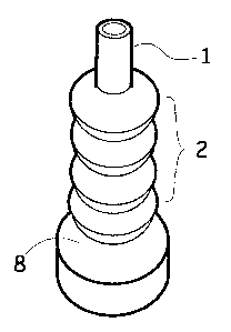
Fig. 1 is a 3/4 view of the invention in the dispensing position
Fig. 2 is a 3/4 view of the invention in the self-sealed or closed position
Fig. 3 is a side cross-sectional view of the invention in the dispensing or
open position
Fig. 4 is a side cross-sectional view of the invention in mid~~ay to the
dispensing
position with a universal screw thread configuration
Fig. 5 is a side cross-sectional view of the invention in the sealed position
Fig. 6 is a top view of the base configuration without screw thread
configuration
Fig. 7 is a side cross-sectional view of the base configuration.
without universal screw thread configuration
DETAILED DESCRIPTION OF THE INVENTION
In the particularly advantageous embodiment of the invention illustrated, to
enable and
disable the dispensing of liquid, moulded of suitable pliable polymeric
plastic material
permitting regular elongation, adjustment, contraction, and closure, comprise
three
sections; an outlet spout 1, a flexible neck configuration 2, and a base
configuration 3,
with or without a universal screw thread configuration 13.
The cylindrical outlet spout 1 section is hollow and cylindrical. The
cylindrical outlet
spout 1 is attatched to the inner juncture 6 of the uppermost ring 5 of the
flexible neck
configuration 2.
The flexible neck configuration 2 comprises a series of similar rings
attatched to each
other at the inner junctures 11 and outer junctures 12.
At the lowermost ring 7 of the flexible neck configuration 2, the outer
juncture of the
lowermost ring 8 is attatched to the outside of the base configuration 8. A
plug 9 at the
center of the base configuration, over which the outlet spout may be engaged
and held
into place in a closed position by a protrusion 4 at the top of the plug 9.
Between the base of the plug 9 and the outside edge of the base configuration
3 are a
series openings 10 to enable liquid to pass through into the neck
configuration and be
dispensed out through the outlet spout 1 when in the dispensing position.
An optional universal screw thread configuration 12 may be found attatched to
the
outside of the base configuration 8.
It will be apparent that various changes and modifications can be made without
departing from the scope of the invention as defined in the claims. Thus,
outlet spout 1,
may be longer, shorter, narrower, or wider. Flexible neck configuration 2, may
include
more, fewer, wider, or narrower rings. And, base configuration 3 may be wider,
narrower, and include a plug 9 that is wider, narrower, taller or shorter. The
protrusion
9 may be wider, shorter, thinner, or thicker. The pass through openings 10 in
the base
configuration 3 may be wider, narrower, fewer or greter in number. The
invention
may be larger or smaller, and wherein the assembly may or may not contain a
universal screw thread configuration 13 for releasable connection of the
system onto a
liquid source, so that a universally applicable assembly may be obtained.

Representative Drawing
A single figure which represents the drawing illustrating the invention.
Administrative Status

2024-08-01:As part of the Next Generation Patents (NGP) transition, the Canadian Patents Database (CPD) now contains a more detailed Event History, which replicates the Event Log of our new back-office solution.

Please note that "Inactive:" events refers to events no longer in use in our new back-office solution.

For a clearer understanding of the status of the application/patent presented on this page, the site Disclaimer , as well as the definitions for Patent , Event History , Maintenance Fee  and Payment History  should be consulted.

Event History

Description Date
Inactive: Adhoc Request Documented 2007-11-28
Application Not Reinstated by Deadline 2007-10-10
Inactive: Dead - No reply to s.30(2) Rules requisition 2007-10-10
Deemed Abandoned - Failure to Respond to Maintenance Fee Notice 2007-02-12
Inactive: Abandoned - No reply to s.30(2) Rules requisition 2006-10-10
Inactive: S.30(2) Rules - Examiner requisition 2006-04-10
Inactive: IPC from MCD 2006-03-12
Amendment Received - Voluntary Amendment 2005-07-12
Amendment Received - Voluntary Amendment 2005-07-08
Inactive: S.30(2) Rules - Examiner requisition 2005-01-17
Application Published (Open to Public Inspection) 2004-08-10
Inactive: Cover page published 2004-08-09
Letter Sent 2003-07-18
Inactive: Correspondence - Prosecution 2003-07-09
Inactive: Office letter 2003-06-19
Letter Sent 2003-05-27
Request for Examination Received 2003-05-14
Request for Examination Requirements Determined Compliant 2003-05-14
All Requirements for Examination Determined Compliant 2003-05-14
Inactive: Advanced examination (SO) 2003-05-14
Inactive: First IPC assigned 2003-04-16
Inactive: Filing certificate - No RFE (English) 2003-03-17
Inactive: Office letter 2003-03-17
Application Received - Regular National 2003-03-17

Abandonment History

Abandonment Date Reason Reinstatement Date
2007-02-12

Maintenance Fee

The last payment was received on 2006-01-09

Note : If the full payment has not been received on or before the date indicated, a further fee may be required which may be one of the following

  • the reinstatement fee;
  • the late payment fee; or
  • additional fee to reverse deemed expiry.

Patent fees are adjusted on the 1st of January every year. The amounts above are the current amounts if received by December 31 of the current year.
Please refer to the CIPO Patent Fees web page to see all current fee amounts.

Fee History

Fee Type Anniversary Year Due Date Paid Date
Application fee - small 2003-02-10
Request for examination - small 2003-05-14
MF (application, 2nd anniv.) - small 02 2005-02-10 2005-01-10
MF (application, 3rd anniv.) - small 03 2006-02-10 2006-01-09
Owners on Record

Note: Records showing the ownership history in alphabetical order.

Current Owners on Record
DAVID R. ZUCCA
Past Owners on Record
None
Past Owners that do not appear in the "Owners on Record" listing will appear in other documentation within the application.
Documents

To view selected files, please enter reCAPTCHA code :


To view images, click a link in the Document Description column. To download the documents, select one or more checkboxes in the first column and then click the "Download Selected in PDF format (Zip Archive)" or the "Download Selected as Single PDF" button.

List of published and non-published patent-specific documents on the CPD .

If you have any difficulty accessing content, you can call the Client Service Centre at 1-866-997-1936 or send them an e-mail at CIPO Client Service Centre.


Document
Description 
Date
(yyyy-mm-dd) 
Number of pages   Size of Image (KB) 
Description 2003-02-09 2 171
Abstract 2003-02-09 1 32
Claims 2003-02-09 1 91
Drawings 2003-02-09 1 32
Representative drawing 2003-04-16 1 5
Claims 2005-07-07 1 69
Drawings 2005-07-07 1 43
Claims 2005-07-11 1 72
Description 2005-07-11 2 133
Abstract 2005-07-11 1 24
Drawings 2005-07-11 1 32
Filing Certificate (English) 2003-03-16 1 169
Acknowledgement of Request for Examination 2003-05-26 1 174
Notice: Maintenance Fee Reminder 2004-11-11 1 119
Notice: Maintenance Fee Reminder 2005-11-13 1 118
Notice: Maintenance Fee Reminder 2006-11-13 1 120
Courtesy - Abandonment Letter (R30(2)) 2006-12-18 1 167
Courtesy - Abandonment Letter (Maintenance Fee) 2007-04-09 1 174
Second Notice: Maintenance Fee Reminder 2007-08-12 1 120
Notice: Maintenance Fee Reminder 2007-11-13 1 122
Correspondence 2003-03-16 1 10
Correspondence 2003-06-18 1 12
Correspondence 2003-07-17 1 12
Fees 2005-01-09 1 45
Fees 2006-01-08 1 49
Fees 2007-11-13 2 81