Note: Descriptions are shown in the official language in which they were submitted.
CA 02419619 2003-02-24
BACKGROUND OF THE INVENTION
[001] This invention relates generally to manually actuated sprayers, and more
particularly to such sprayers having an orifice cup with a discharge orifice
through which
product is dispensed upon sprayer actuation.
[002] The known orifice cup is mounted within the discharge passage of
manually actuated hand-held sprayers, the cup being normaily held in place as
its
cylindrical side wall is press fitted within the wall of a circular bore for
tight frictional
engagement therewith. Spin mechanics in the form of a spin chamber and
tangentials
leading thereto may be formed on the inner surface of the circular base wall
of the
orifice cup. Upon manual actuation of the sprayer as, for example, a pump
sprayer
actuated by depressing a plunger head or such as a trigger actuated sprayer
actuated
by the squeezing of the trigger, significant pressures are developed as the
liquid product
is forced through a constricted discharge passage and through the spin
mechanics
before issuing through the discharge orifice in the form of a spray. Of
course, with no
spin mechanics provided or with an immobilized spin mechanics feature, the
liquid
issues from the discharge orifice in the form of a stream.
[003] The known orifice cup is molded as having a cylindricai skirt wall, and
an
annular retention bead projecting radially outwardly of the side of the cup
near the front
end thereof. The orifice cup is typically force fitted within the cylindrical
bore at the
terminal end of the discharge passage in tight frictional engagement between
the
cylindrical side wall of the cup and the cylindrical bore wall. The annular
retention bead
is designed to project into the confronting cylindrical portion of the pump
sprayer body
]
CA 02419619 2003-02-24
serving to assist in retaining the orifice cup in place within the bore as
well as in acting
as a seal between the orifice cup and the bore of the discharge passage.
[004] Occasionally the orifice cup will dislodge from its bore upon persistent
high pressures acting on its underside surface during sprayer actuation. When
this
occurs the orifice cup may be shifted sufficiently downstream such that its
annular
retention/sealing bead moves out of its mating groove and even out of the
terminal end
of the bore. Thus, the seal between the orifice cup and the wall of the bore
is disturbed
thereby opening up a passage, however, minute, for liquid to leak through.
This
presents an unsightly and totally unacceptable condition.
[005] Also where spin mechanics is formed on the inner surface of the base of
the orifice cup which cooperates with a confronting probe on the sprayer body
which
extends into the cup, any slight shifting movement of the orifice cup in a
downstream
direction in response to the high pressure exerted will cause both leakage of
product
and may defeat the ability of the spin mechanics to function to swirl the
product and
break it up into a fine mist spray.
[006] The need therefore arises for improvement upon the retentivity and the
sealability of the orifice cup within its bore.
SUMMARY OF THE INVENTION
[007] It is therefore an object of the present invention to provide an orifice
cup
for a manually actuated sprayer which is positiveiy retained in place against
dislodgement and is sealed in its bore against leakage in a manner requiring
but a
2
CA 02419619 2007-10-03
minor modification thereby incurring little costs for the same yet is highly
efficient in
improving upon the retentivity and sealability of the orifice cup in its bore.
In keeping with this objective, the orifice cup according to the invention has
its
skirt molded to frusto-conical shape tapering outwardly in an upstream
direction of
flow through the orifice. The circular base of the orifice cup has an outer
diameter
substantially the same as the wall diameter of the discharge bore. The cup
skirt wall
tapers radially outwardly relative to that outer diameter such that when force
fitted into
its bore the entirety of the skirt wall bears tightly and sealingly against
the bore wall
for both positively retaining the orifice cup in place without the likelihood
of
dislodgement due to pressure forces of the discharged fluid, and for sealing
the orifice
cup in its bore without the likelihood of any leakage from around the cup.
Other objects, advantages, and novel features of the invention will become
more apparent from the following detailed description of the invention when
taken in
conjunction with the accompanying drawings.
BRIEF DESCRIPTION OF THE DRAWINGS
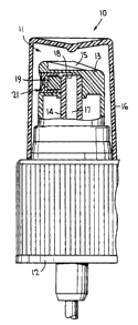
Figure 1 is a side view, partly in section, of a manually actuated sprayer
with its
sprayer head incorporating the improved orifice cup according to the
invention;
Figure 2 is a view taken substantially along the line 2-2 of Figure 3; and
Figure 3 is a sectional view taken substantially along the line 3-3 of Figure
2 of
the orifice cup according to the invention at an enlarged scale.
-3-
CA 02419619 2007-10-03
DETAILED DESCRIPTION OF THE INVENTION
Turning now to the drawings wherein like reference characters refer to like
and
corresponding parts throughout the several views, a manually actuated sprayer
is
generally designated 10 in Figure 1 which is in the form of a pump sprayer as
represented
by the type disclosed in U.S. Patent 4,051,983, commonly owned herewith. Of
course
any other type of manually actuated hand-held sprayer is capable of
incorporating the
invention, such a trigger actuated pump sprayer, an aerosol sprayer, a squeeze
bottle
sprayer, etc.
Sprayer 10 has a body member 11 which includes a closure 12 for mounting the
sprayer to a container (not shown) of product to be sprayed. The body member
further
includes a plunger head 13 mounted on a hollow plunger stem 14, which stem has
a
pump piston (not shown) reciprocable within a pump cylinder (not shown) in a
manner
known in this art upon the application of external finger pressure applied to
top 15 of the
plunger head. An overcap 16 is of course first removed by the operator before
the
plunger is reciprocated.
The piston stem defines a discharge passage 17 which communicates with a
transversely extending hollow cylindrical bore 18 provided in the head. The
plunger
head has a cylindrical probe 19 extending transversely and coaxially with bore
18.
Orifice cup 21 in accordance with the invention is similar in many respects to
that
disclosed in U.S. Patent 4,051,983 issued October 4, 1977 in that it is
thimble-shaped
having a base wall 22 containing a discharge 23 through which the liquid
product issues in
-4-
CA 02419619 2007-10-03
the form of a fine mist spray as known in this art. The base wall has an outer
diameter
which is substantially the same as or slightly greater than the diameter of
the wall of
cylindrical bore 18 in its relaxed condition. An annular retention bead 24 is
formed
integrally with the orifice cup and extends radially outwardly of the side
wall of the base
at an enlarged diameter d compared to the outer diameter of the base wall.
Likewise an
inner face 25 of the base wall is formed with the known spin mechanics 26
which
includes a spin chamber 27 coaxial with the discharge orifice and a plurality
(usually 3)
tangential channels 28 leading into the spin chamber for imparting the swirl
to the liquid
in the spin chamber causing the liquid to emerge from the orifice in the form
of a fine
mist spray.
Orifice cup 21 further has an integrally molded skirt 29, probe 19 extending
into the hollow of the skirt when the orifice cup is installed in cylindrical
bore 18.
The diameter of the probe is slightly less than the inner diameter of the
skirt defining
an annular gap 31 defining an extension of discharge passage 17.
Alternatively, axial
ribs or grooves can be provided on the confronting walls of probe 19 and/or
bore 18.
And the probe has a flat terminal end 32 which confronts channels 28 so as to
define
tangential flow passageways therewith. In thus manner, and as well known in
this art, after the pump is primed with liquid, each downward stroke applied
to the
plunger head pressurizes the liquid in the pump chamber (not shown) and forces
liquid under pressure through an open discharge valve (not shown) along
discharge
passage 17, gap 31, and tangentials 28 which subject the liquid to a vortex in
spin
-5-
CA 02419619 2003-02-24
chamber 27 causing the swirled liquid to issue through the discharge orifice
23 in the
form of a fine mist spray.
[0016] Specifically in accordance with the invention, skirt 29 is molded into
a
frusto-conical shape as shown in detail in Fig. 3. Thus, the outer wall of
skirt 29 tapers
radially outwardly in an upstream direction of flow from diameter d at base
22, to a
maximum outer diameter D adjacent the free end of the skirt. This maximum
diameter
D is substantially the same as diameter dd of retention bead 24, and assists
in more
easily removing the molded part from the mold. Also it is noted that the free
end of the
skirt may be chamfered as at 33 to more easily facilitate insertion of the
orifice cup
within cylindrical bore 18
[0017] As an example of several of the dimensions involved, without limiting
the
invention in any manner, diameter d can be 0.179 inches, diameters dd and D
can be
0.185 inches, and the length of the reverse taper of the skirt can be 0.096
inches.
[0018] The orifice cup is inserted into cylindrical bore 18 of the plunger
head in
any normal manner known in this art. The plastic material chosen for the
plunger head
is sufficiently forgiving such that the orifice cup with its reverse taper is
forced fitted into
the cylindrical bore 18 without inducing any cracking in either the orifice
cup or in the
plunger head. The tight frictional fit effected between the orifice cup and
the wall of the
cylindrical bore has been shown to positively retain the orifice cup in place
without
dislodgement even after repeated pump strokes subjecting the inner face 25 of
the cup
to fluid pressures even exceeding those which would normally occur in
practice. The
reverse taper of the skirt functions to not only vastly improve upon the tight
frictional
6
CA 02419619 2003-02-24
engagement with the cylindrical bore wall, but functions to avoid any leakage
of product
at the inner face between the cap skirt and the wall of bore 18.
[0019] Retention bead 24 is optional and may be provided as an additional
means of retention of the orifice cup in place.
[0020] Although the present invention has been described with reference to a
fingertip actuated pump sprayer, it is not so limited, but is rather likewise
fully adaptable
to an aerosol sprayer, a trigger actuated pump sprayer, a squeeze bottle
sprayer, etc.,
within the scope of the invention. The reverse taper of the orifice cup skirt
functions
equally well in all these type sprayers to retain the orifice cup positively
in place within
its cylindrical bore without dislodgement even under extreme and repeated high
pressures of the dispensed fluids.
[0021] Obviously, many modifications and variations of the present invention
are
made possible in the light of the above teachings. It is therefore to be
understood that
within the scope of the appended claims the invention may be practiced
otherwise than
as specifically described.
7