Language selection

Search

Patent 2419667 Summary

Third-party information liability

Some of the information on this Web page has been provided by external sources. The Government of Canada is not responsible for the accuracy, reliability or currency of the information supplied by external sources. Users wishing to rely upon this information should consult directly with the source of the information. Content provided by external sources is not subject to official languages, privacy and accessibility requirements.

Claims and Abstract availability

Any discrepancies in the text and image of the Claims and Abstract are due to differing posting times. Text of the Claims and Abstract are posted:

  • At the time the application is open to public inspection;
  • At the time of issue of the patent (grant).
(12) Patent: (11) CA 2419667
(54) English Title: SPRING-LOADED ROTATIONAL LIMIT STOP
(54) French Title: BUTEE DE FIN DE COURSE ROTATIONNELLE A RESSORT
Status: Expired
Bibliographic Data
(51) International Patent Classification (IPC):
  • F16K 31/44 (2006.01)
  • E03C 1/04 (2006.01)
  • F16K 31/60 (2006.01)
(72) Inventors :
  • JONES, JACOB (United States of America)
  • CONLISK, CHRISTOPHER W. (United States of America)
  • MCMAINS, KYLE H. (United States of America)
  • MCNERNEY, GERALD J. (United States of America)
(73) Owners :
  • DELTA FAUCET COMPANY (United States of America)
(71) Applicants :
  • MASCO CORPORATION OF INDIANA (United States of America)
(74) Agent: PIASETZKI NENNIGER KVAS LLP
(74) Associate agent:
(45) Issued: 2006-02-07
(22) Filed Date: 2003-02-21
(41) Open to Public Inspection: 2003-09-19
Examination requested: 2003-05-01
Availability of licence: N/A
(25) Language of filing: English

Patent Cooperation Treaty (PCT): No

(30) Application Priority Data:
Application No. Country/Territory Date
10/101,890 United States of America 2002-03-19

Abstracts

English Abstract

A rotational limit stop comprising a substantially circular disc having an upper surface, a lower surface and a perimeter surface, the perimeter surface containing a plurality of teeth on one portion thereof, a central aperture passing through the center of the circular disc, and a plurality of resilient spring legs extending downwards from the lower surface of the disc, such that the resilient spring legs of the rotational limit stop flex to accommodate the compression forces as a faucet assembly containing the rotational limit stop is being assembled.


French Abstract

Une butée de fin de course rotationnelle comportant un disque essentiellement circulaire ayant une surface supérieure, une surface inférieure et une surface périmétrique, cette dernière contenant une pluralité de dents sur une partie de celle-ci, une ouverture centrale passant au centre du disque circulaire et une pluralité de jambes de force élastiques s'étendant vers le bas à partir de la surface inférieure du disque, de manière que les jambes de force élastiques de la butée de fin de course rotationnelle fléchissent pour accommoder les forces de compression, alors qu'un robinet contenant la butée de fin de course rotationnelle est assemblé.

Claims

Note: Claims are shown in the official language in which they were submitted.


What is claimed is:

Claim 1. A rotational limit stop comprising:
a substantially circular disc having an upper surface,
a lower surface and a perimeter surface, the perimeter
surface containing a plurality of teeth on one portion
thereof,
a central aperture passing through the center of the
circular disc, and
a plurality of resilient spring legs extending
downwards from the lower surface of the disc, such that the
resilient spring legs of the rotational limit stop flex to
accommodate the compression forces as a faucet assembly
containing the rotational limit stop is being assembled.

Claim 2. The rotational limit stop according to claim 1,
wherein the perimeter surface of the disc is divided into a
teeth section containing the plurality of teeth, an
indented section, and a smooth section.

Claim 3. The rotational limit stop according to claim 2,
further comprising:
a handle tab extending above and below the disc
adjacent to the perimeter surface, the handle tab being
situated in the smooth portion of the disc; and
a stop wall also extending upwards from the upper
surface of the disc adjacent the perimeter surface, the
stop wall also being situated in the smooth portion of the
disc but spaced apart from the handle tab.

Claim 4. The rotational limit stop according to claim 3,
wherein the disc contains an annular portion immediately

8~


surrounding the central aperture, the annular portion being
raised above the upper surface of the disc.

Claim 5. The rotational limit stop according to claim 4,
further comprising:
a plurality of temperature indicating bumps raised
above the upper surface of the disc and situated in the
indented portion of the disc; and
a calibration line situated with, but distinguished
from, the temperature indicating bumps.

Claim 6. The rotational limit stop according to claim 5,
wherein the temperature indicating bumps are spaced apart
such that each bump corresponds to approximately three
degrees Fahrenheit when the rotational limit stop is
installed within a faucet assembly.

Claim 7. The rotational limit stop according to claim 6,
wherein the rotational limit stop is constructed as a
single unit from an elastomeric material.

Claim 8. A faucet assembly comprising:
a valve assembly having a valve sprocket extending
axially therefrom, the valve sprocket having teeth around
its perimeter;
a flow control knob fitted onto the valve assembly,
the flow control knob having 1) a central opening, the
central opening having mating ridges around its perimeter,
2) a base surface extending radially from the central
opening, 3) a perimeter lip surrounding the base surface,
the perimeter lip having an inner surface, and 4) a
plurality of engaging ridges along the inner surface of the

9


perimeter lip, such that the valve sprocket extends through
the central opening of the flow control knob;
a rotational limit stop fitted within the flow control
knob, the rotation limit stop comprising 1) a substantially
circular disc having an upper surface, a lower surface and
a perimeter surface, the perimeter surface containing a
plurality of teeth, 2) a central aperture passing through
the center of the circular disc, 3) a plurality of
resilient spring legs extending downwards from the lower
surface of the disc, such that the teeth around the
perimeter surface engage the engaging ridges along the
inner surface of the perimeter lip, thereby causing the
rotational limit stop to rotate with the flow control knob;
a temperature knob fitted onto of the rotational limit
stop; and
a temperature knob cover, covering the temperature
knob, wherein the resilient spring legs of the rotational
limit stop flex to accommodate the compression forces as
the faucet assembly is being assembled.

Claim 9. The faucet assembly according to claim 8, wherein
the disc of the rotational limit stop contains an annular
portion immediately surrounding the central aperture, the
annular portion being raised above the upper surface of the
disc.

Claim 10. The faucet assembly according to claim 9,
wherein the downwardly extending spring legs are situated
outside of the raised annular portion of the disc.


Claim 11. The faucet assembly according to claim 10,
further comprising:
a plurality of temperature indicating bumps raised
above the upper surface of the disc of the rotational limit
stop, and situated in the indented portion of the disc; and
a calibration line situated with, but distinguished
from, the temperature indicating bumps.

Claim 12. The faucet assembly according to claim 11,
wherein the rotational limit stop is constructed as a
single unit from an elastomeric material.

11

Description

Note: Descriptions are shown in the official language in which they were submitted.


' CA 02419667 2003-02-21
.
SPRING-LOADED ROTATIONAL LIMIT STOP
Field of the Invention
This invention relates to a spring-loaded disc having
thereon a rotational limit stop for a faucet valve
assembly.
Background of t:he Invention
Primarily in single handle faucet assemblies where the
valve hosts a temperature dial and a volume dial on the
same faucet stem, the temperature mechanism and the volume
mechanism are stacked on top of each other. As each of the
respective volume and temperature components are designed
to its respective tolerances, the cumulative tolerance
effect can become large enough for a user to feel a wobble
or slack within the faucet configuration. These loose
controls are, unfortunately, interpreted as inferior in
quality. However, without these tolerances, a faucet
assembly may result, in which the controls are stiff or
unmovable. In order to solve this problem, the industry
has resorted to using a number of devices. For example,
one proposed solution involved using a screw to take up the
tolerance variations in the assembly. The screw tightened
down the assembly until the temperature and volume controls
moved in a satisfactory manner, according to the installer
of the faucet. However, this method is highly subjective
and depended upon the skill and "feel" of the installer,
and oftentimes resulted in faucets in which the volume
control seized to the temperature control as a result of an
over-tightened screw.
1

CA 02419667 2003-02-21
115-3557-U
Another solution involved the use of a foam gasket
within the assembly in order to compensate for the gap
designed into the stack configuration. Here, the stack was
simply tightened together compressing the foam gasket. In
this way, the gasket served to remove the slack and give
the impression of a compact, well-constructed faucet, one
without wobble. Although the foam gasket is a simple,
inexpensive solution to this problem, the foam gasket tends
to weather or permanently deform in the fluid environment
of the faucet. As a result, the resilience of the foam is
destroyed and the foam can no longer provide the cushioning
forces required in the faucet stack. This would once again
cause the wobble within the faucet assembly.
Summary of the Invention
In order to solve the problems recited above, the
instant invention discloses a spring-loaded disc having the
rotational limit stops thereon. As proposed, a one-piece
disc takes up the tolerance variation between the faucet
components, as these components are stacked upon each
other. This tolerance variation is converted into a
constant force output targeted to provide the force
required to achieve a moderate balance between the
tolerance gap causing the volume control handle to wobble
and the excessive interference caused by the over-
tightening of the temperature knob.
2

CA 02419667 2003-02-21
. ' ' 115-3557-U
Brief Description of the Drawinas
The many objects, features and advantages of the
present invention will become apparent to one skilled in
the art when the following detailed description of the
preferred embodiment is read together with the attached
drawing, wherein like reference numerals refer to like
components throughout and wherein:
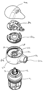
FIG. 1 is an exploded perspective view of the faucet
assembly incorporating the spring-loaded disc according to
the instant invention;
FIG. 2 is a top plan view of the spring-loaded disc
according to the instant invention;
FIG. 3 is a sectional view of the spring-loaded disc
according to the instant invention taken along the line 3-
3;
FIG. 4 is a bottom perspective view of the spring-
loaded disc according to the instant invention; and.
FIG. 5 is a partial cross sectional view of the
spring-loaded disc according to the instant invention
incorporated within a representative faucet assembly.
Description of the Preferred Embodiment
Referring to Figure 1, the faucet assembly
comprises a valve assembly 10, a flow control knob 20
fitted upon the valve assembly 10, a rotational limit stop
50 according to the invention and placed within the flow
control knob 20, a temperature knob 80 placed upon the
rotational limit stop 50, and a temperature knob cover 90.
The flow control knob 20 comprises a central opening 22, a
3

CA 02419667 2003-02-21
' ' 115-3557-U
base surface 24 extending radially from the central opening
22, and a perimeter lip 26 projecting upwards and
surrounding the base surface 24. The perimeter lip 26
forms the knob body 27. Extending from the flow control
knob body 27 is a flow control handle 21. A cold
temperature stop 28 extends inwards from the inner surface
30 of the perimeter lip 26. Also along the inner surface
30 of the perimeter lip 26 are a plurality of engaging
ridges 32. As shown in Figure l, the engaging ridges 32
extend from the cold temperature stop 28 partially around
the inner circumference of the perimeter lip 26. Although
not shown in Figure 1, it is possible for the engaging
ridges 32 to extend entirely around the inner surface of
the perimeter lip 26.
The central opening 22 contains a plurality of mating
ridges 34 around its perimeter. The central aperture 22 is
sized so as to matingly engage a valve sprocket 12
extending from the top of valve assembly 10. ~ As the flow
control knob 20 is placed upon the valve assembly 10, the
teeth 14 around the valve sprocket 12 engage the mating
ridges 34 of the flow control knob 20, allowing the flow
control knob 20 to adjust the valve by rotating the flow
control knob 20.
The rotational limit stop 50 is sized to be received
within the perimeter lip 26 of the flow control knob 20.
Referring also to Figures 2-4, the rotational limit stop 50
comprises a substantially circular disc 52 having an upper
surface 54, a lower surface 56, and an outer circumference
58. Extending upwards from the upper surface 54, and along
the outer circumference 58 is a handle 60 and a stop wall
62. The handle 60 is spaced apart from the stop wall 62.
As shown in Figures 3 and 4, the handle 60 also extends
4

CA 02419667 2003-02-21
. 115-3557-U
downwards from the lower surface 56 of the disc 52. This
lower extension 60a provides structural reinforcement to
the disc 52. Adjacent the stop wall 62, and running
partially around the outer circumference 58, are a
plurality of teeth 64. An indented section 66 is located
along the outer circumference 58 between the teeth 64 and
the handle 60. Along the indented section 66 and raised
from the upper surface 54, is a plurality of temperature
indicating bumps 68. As shown in Figure 2, one of the
temperature indicating bumps 68, the calibration line 68a,
is differentiated from the others by, in this example,
extending the bump 68a upwards. This calibration line 68a
allows the installer to properly align the rotational limit
stop 50 within the flow control knob 20. In a preferred
embodiment of the invention, each temperature-indicating
bump 68 corresponds to approximately three degrees
Fahrenheit on the temperature knob 80. Extending outwards
from the outer circumference 58, and in the area of the
handle 60 are a plurality of alignment teeth 69, for
aligning the rotational limit stop 50 within the flow
control knob 20.
As shown in Figure 2, a central aperture 70 is located
at the center of the disc 52. The valve sprocket 12 of
valve assembly 10 extends upwards through both the flow
control knob 20 and the rotational limit stop 50. As shown
in Figure 1, the central aperture 70 corresponds to the
central opening 22. Extending radially outwards from the
central aperture 70 is the disc surface 72. As shown in
Figure 3, the disc surface 72 includes a raised section 74
immediately adjacent the central aperture 70. Extending
downwards from the disc surface 72 is a plurality of
resilient spring legs 76. In the preferred embodiment

CA 02419667 2003-02-21
115-3557-U
illustrated in Figure 4, four pairs of spring legs 76a,
76b, are spaced around the disc surface 72 of the
rotational limit stop 50.
Preferably, the rotational limit stop 50 is
constructed from an elastomeric or plastic material, for
example a material marketed under the trade name "celanex."
The material provides a certain resiliency to the spring
legs 76 allowing the spring legs 76 to flex and properly
accommodate the compression forces as the faucet is being
assembled.
Referring to Figures 1 and 5, the faucet is assembled
by fitting the flow control knob 20 onto the valve assembly
10, so that the valve sprocket 12 engages the mating ridges
34 of the flow control knob 20. The rotational limit stop
50 is aligned within the flow control knob 20 so that the
calibration line 68a is lined up with the cold temperature
stop 28 of the flow control knob 20. Further, the
alignment teeth 68 are properly positioned within the
volume control knob 20. The temperature knob 80 is then
fitted on top of the rotational limit stop 50. In this
preferred embodiment, a screw (not shown) is employed to
secure the temperature knob 80 to the rotational limit stop
50. The temperature knob cover 90 is then snapped into
place over the temperature knob 80. As is clear to anyone
skilled in the art, the screw attachment means employed
with temperature knob 80 and the snap fit employed with the
temperature knob cover 90 may be substituted with other
attaching and securing means.
While the invention has been described in what is
considered to be a preferred embodiment, other variations
and modifications will become apparent to those skilled in
6

CA 02419667 2003-02-21
,' ' 115-3557-U
the art. It is intended, therefore, that the invention not
be limited to the illustrative embodiment but be
interpreted within the full spirit and scope of the
appended claims.
,;
7

Representative Drawing
A single figure which represents the drawing illustrating the invention.
Administrative Status

For a clearer understanding of the status of the application/patent presented on this page, the site Disclaimer , as well as the definitions for Patent , Administrative Status , Maintenance Fee  and Payment History  should be consulted.

Administrative Status

Title Date
Forecasted Issue Date 2006-02-07
(22) Filed 2003-02-21
Examination Requested 2003-05-01
(41) Open to Public Inspection 2003-09-19
(45) Issued 2006-02-07
Expired 2023-02-21

Abandonment History

There is no abandonment history.

Payment History

Fee Type Anniversary Year Due Date Amount Paid Paid Date
Registration of a document - section 124 $100.00 2003-02-21
Application Fee $300.00 2003-02-21
Request for Examination $400.00 2003-05-01
Maintenance Fee - Application - New Act 2 2005-02-21 $100.00 2005-01-05
Final Fee $300.00 2005-11-28
Maintenance Fee - Application - New Act 3 2006-02-21 $100.00 2006-01-11
Maintenance Fee - Patent - New Act 4 2007-02-21 $100.00 2007-01-05
Maintenance Fee - Patent - New Act 5 2008-02-21 $200.00 2008-01-09
Maintenance Fee - Patent - New Act 6 2009-02-23 $200.00 2009-01-09
Maintenance Fee - Patent - New Act 7 2010-02-22 $200.00 2010-01-07
Maintenance Fee - Patent - New Act 8 2011-02-21 $200.00 2011-01-25
Maintenance Fee - Patent - New Act 9 2012-02-21 $200.00 2012-01-19
Maintenance Fee - Patent - New Act 10 2013-02-21 $250.00 2013-01-18
Maintenance Fee - Patent - New Act 11 2014-02-21 $250.00 2014-01-22
Maintenance Fee - Patent - New Act 12 2015-02-23 $250.00 2015-01-19
Registration of a document - section 124 $100.00 2015-06-26
Maintenance Fee - Patent - New Act 13 2016-02-22 $250.00 2016-01-12
Maintenance Fee - Patent - New Act 14 2017-02-21 $250.00 2017-01-13
Maintenance Fee - Patent - New Act 15 2018-02-21 $450.00 2018-01-12
Maintenance Fee - Patent - New Act 16 2019-02-21 $450.00 2019-01-15
Maintenance Fee - Patent - New Act 17 2020-02-21 $450.00 2020-01-15
Maintenance Fee - Patent - New Act 18 2021-02-22 $450.00 2020-12-22
Maintenance Fee - Patent - New Act 19 2022-02-21 $458.08 2022-01-13
Owners on Record

Note: Records showing the ownership history in alphabetical order.

Current Owners on Record
DELTA FAUCET COMPANY
Past Owners on Record
CONLISK, CHRISTOPHER W.
JONES, JACOB
MASCO CORPORATION OF INDIANA
MCMAINS, KYLE H.
MCNERNEY, GERALD J.
Past Owners that do not appear in the "Owners on Record" listing will appear in other documentation within the application.
Documents

To view selected files, please enter reCAPTCHA code :


To view images, click a link in the Document Description column. To download the documents, select one or more checkboxes in the first column and then click the "Download Selected in PDF format (Zip Archive)" or the "Download Selected as Single PDF" button.

List of published and non-published patent-specific documents on the CPD .

If you have any difficulty accessing content, you can call the Client Service Centre at 1-866-997-1936 or send them an e-mail at CIPO Client Service Centre.


Document
Description 
Date
(yyyy-mm-dd) 
Number of pages   Size of Image (KB) 
Abstract 2003-02-21 1 17
Description 2003-02-21 7 257
Claims 2003-02-21 4 126
Drawings 2003-02-21 3 75
Representative Drawing 2003-05-27 1 10
Cover Page 2003-08-22 2 42
Cover Page 2006-01-10 1 40
Fees 2006-01-11 1 32
Assignment 2003-02-21 10 381
Prosecution-Amendment 2003-05-01 1 34
Prosecution-Amendment 2004-01-14 2 47
Fees 2005-01-05 1 30
Correspondence 2005-11-28 1 35
Correspondence 2014-03-18 9 289
Correspondence 2014-02-24 8 211
Correspondence 2014-03-14 31 984
Correspondence 2014-03-25 1 18
Correspondence 2014-03-26 1 27
Assignment 2015-06-26 70 4,955