Note: Descriptions are shown in the official language in which they were submitted.
CA 02419952 2003-02-20
WO 02/21424 PCT/USO1/27372
SYSTEM AND METHOD FOR USING RADIO FREQUENCY
IDENTIFICATION IN RETAIL OPERATIONS
[0001] This application claims the benefit of U.S. Provisional Application
No. 60/ 229,599 filed September 5, 2000, which is herein incorporated by
reference in its entirety.
BACKGROUND
Field of the Invention
[0002] The present invention relates to the use of radio frequency
identification (RFID) in retail operations. In particular, the present
invention relates to systems and methods for using RFID to facilitate a
variety of processes within the supply chain of a retail organization.
Baclc~round of the Invention
[0003] Radio frequency identification (RFID) is a technology that uses
radio frequency waves to transfer data between a reader and a moveable
item. Figure 1 shows a high level view of an RFID system that includes a
tag, an antenna, a reader and a host computer. As shown, the antenna
captures the tag ID number, the reader then interprets the radio frequency
into digital information and the host is a software database.
[0004] In RFID systems, the type of tag used can vary greatly. The tag
may be read-only or read/write capable. The tag preferably has an anti-
collision characteristic to provide the ability to read/write one or many
tags at a time. The tag may vary in size from a thumbnail (or even
SUBSTITUTE SHEET (RULE 26)
CA 02419952 2003-02-20
WO 02/21424 PCT/USO1/27372
[0005] smaller) to the size of a brick. The price of individual tags may
also vary greatly currently in a range from $.30 to $250.00 per tag.
Naturally, as technology develops, new characteristics are added and the
price decreases.
[0006] RFID technology offers advantages over other systems, such as
bar coding. To begin with, RFID technology is contactless (non-contact)
and is not dependent on line of sight. Moreover, RFID technology is
effective in visually and environmentally challenging conditions where
barcode or other optically-read technologies would be useless. In
addition, RFID technology offers fast read speed, in most instances
responding in less than 100 milliseconds using current technology. RFID
technology also offers extremely high data accuracy and makes it possible
to provide read/write capability for interactive applications.
[0007] Currently, RFID technology is used to tag pallets or cartons;
vehicles; company assets; items such as apparel, luggage and laundry;
people, livestock or pets; and high-value electronics such as computers
and TVs. Current applications for RFID technology include security
access; loss prevention; asset and inventory tracking; automatic toll
collection; wildlife and livestock tracking; house arrest monitoring
systems; manufacturing work in process data; shipping and intermodal
containers and air cargo tracking; trailer maintenance; and railroad car
tracking.
[0008] Although various proposals for using RFID technology have been
put forward and attempted, there remains a need for a system and method
SUBSTITUTE SHEET (RULE 26)
2
CA 02419952 2003-02-20
WO 02/21424 PCT/USO1/27372
for using RFID technology to optimize the supply chain and operations of
a retail organization. Moreover, as improvements in RFID technology
and components occur, there will be greater opportunities to optimize
supply chains of all types, particularly those of retail organization.
SUMMARY OF THE INVENTION
[0009] The present invention provides a system and method for using
RFID technology in a supply chain to provide advantages in each stage of
the supply chain. The system is particularly useful in the context of
improving operations and efficiency in a retail organization. One
example of a retail organization that can benefit from the present
invention is a retailer of ready-to-wear garments and accessories,
including jewelry, eyewear, personal care and home products, baby
products and toys. The invention is, however, useful in other
environments as well.
[0010] The supply chain for a typical retail'organization includes various
stages, such as factories for producing products, a freight
forwardinglconsolidator, a de-consolidator, distribution centers, poolers
and stores or retail outlets. As used herein, the term "consolidator" refers
to a facility (often a third party facility) that the manufacturers ship the
product to. The product is "consolidated" at this point into containers or
"loads" for shipping purposes. "De-consolidator" - refers to a facility
(often a third party facility) that the product is centrally received at. The
product is then sorted into shipments (trailers) that are sent to the
respective distribution centers. "Pooler" refers to a facility (often a third
SUBSTITUTE SHEET (RULE 26)
-3-
CA 02419952 2003-02-20
WO 02/21424 PCT/USO1/27372
party facility) that receives trailer shipments of product from the
distribution center then in turn breaks out the shipments into store
delivery shipments, and delivers the goods to the store. "SCaN," in the
context of shipment tracking refers to a system used to track and monitor
the carton level movement of product within the supply chain.
"SuperRat" refers to touch screen monitors used as the touch screen
manual receiving stations that are used in the present invention. The
present invention is applicable, but not limited to, retail organizations and
non-retail organizations having this type of supply chain.
[0011 ] In accordance with the system and method of the present
invention, an RFID tag is associated with each item (or carton or person)
to be tracked. In a retail organization that sells ready-to-wear garments,
for example, an RFID tag is associated with each ready-to-wear garment.
The tag may be sewn into the garment and/or placed into a tag that is
attached after the garment is manufactured.
[0012] The system and method of the present invention can use the
various forms of RFID technology currently available for using radio
frequency waves to transfer data between a reader and a moveable item.
Since the technology relating to RFID is changing rapidly, the techniques,
processes and systems described herein are not limited to any particular
RFID technology, but preferably use state of the art RFID technology to
obtain the greatest cost/benefit for a particular application or set of
applications.
SUBSTITUTE SHEET (RULE 26)
-4-
CA 02419952 2003-02-20
WO 02/21424 PCT/USO1/27372
[0013] In addition to tags, the system further comprises a plurality of tag
readers at locations throughout the supply chain. As used herein, "tag
reader" is also intended to encompass devices for writing data onto tags
that have a read/write capability. The "tag readers" preferably include
both an antenna for capturing signals from the tags and a "reader" that
interprets the radio frequency into digital information. The "tag reader"
should also include a transmitter if the tag reader is to be used o write
data onto the tags. The tag readers preferably come in various forms to
accommodate the particular need. For example, fixed tag readers along a
conveyor belt or tunnel may be provided at a loading dock or distribution
center, while hand held tag readers may be provided to associates at stores
or distribution centers.
[0014] The system also includes at least one and typically a plurality of
host computers for receiving and processing information from the tag
readers and interfacing with other inventory, operations and logistics
systems. If the tag readers are designed to provide information in digital
form, then the host computers) receive and process the information in
this form. Naturally, the conversion to digital form could take place in the
host computer, if desired.
[0015] The use of RFID technology yields savings throughout the retail
supply chain, including increased recovery of vendor quality chargebacks;
a reduction of freight loss; increased accuracy of store receiving;
increased data integrity of store inventory management; a reduction of
store backroom lost sales; increased efficiency and effectiveness of store
SUBSTITUTE SHEET (RULE 26)
-5-
CA 02419952 2003-02-20
WO 02/21424 PCT/USO1/27372
loss prevention activities; increased data integrity of merchandise returns;
enhanced vendor shortship visibility; improved distribution center
picking / stocking labor efficiency, and improved distribution center
inventory accuracy. The use of RFID technology also makes it possible
to improve loss prevention procedures at each step in the supply chain.
[0016] The following paragraphs provide an overview of applications of
RFID technology to retail operations and supply chains to enhance
operational efficiency and provide a comprehensive systematic loss
prevention program.
VENDOR QUALITY CHARGEBACKS / INVENTORY ACCURACY
[0017] The system and method of the present invention applies RFID to
enable the Retailer (e.g., ready-to-wear apparel and accessory retailer) to
identify which manufacturers are producing products of poor quality.
Assuming that the RFID tag is associated with the item, in one example
where the item is a garment, the RFID tag could be sewn into the garment
and the vendor/manufacturer is identified in the RFID memory, the
Retailer would have the ability to take customer returns due to poor
quality and trace the unit back to the vendor/manufacturer. Thus, this
system facilitates the Retailer's efforts to seek recompense from the
vendor. Furthermore, the Retailer could implement process changes or
stop purchasing from that particular manufacturer until product quality
and quality control has been improved and confirmed.
FREIGHT LOSS
SUBSTITUTE SHEET (RULE 26)
_6_
CA 02419952 2003-02-20
WO 02/21424 PCT/USO1/27372
[0018] The Retailer typically loses an opportunity to recoup freight losses
during transit. Scanning the RFID tagged units before delivering to the
poolers and during the store delivery process will enable the Retailer (e.g.,
ready-to-wear retailer) to identify any discrepancies and provide the
documentation to support freight claims. Loss prevention is improved
when discrepancies can be quickly detected and traced to one participant
in the supply chain, e.g., the shipper.
STORE RECEIVING
[0019] In this area a portion of the potential savings comes from reducing
labor costs incurred during the receiving process. However, the largest
percentage of the benefits comes from recouping lost margin dollars
resulting from inaccurate receiving data. Store inventory management
RFID technology can be applied to facilitate inventory physical counts at
the stores. A Retailer (e.g., ready-to-wear retailer) currently spends
money either directly or by hiring 3rd party companies to come into stores
and perform physical counts. This annual cost increases as the Retailer
expands its store base.
[0020] Furthermore, field staff time spent on taking regular and ad hoc
physical counts can be reduced significantly or eliminated through RFID.
A benefit that is difficult to quantify is the ability of merchandise
planning and distribution groups to make better decisions because they
would base their decisions on more accurate inventory data. In addition,
loss prevention is improved because it is possible to track products.
SUBSTITUTE SHEET (RULE 26)
CA 02419952 2003-02-20
WO 02/21424 PCT/USO1/27372
STORE LOSS PREVENTION
[0021] RFID technology can potentially replace sensor tag technology in
the stores to prevent both customer theft and employee theft. One
example of a sensor tag that is used to assist with inventory control is a
SENSORMATIC tag. The sensor tag solution is expensive for two
reasons: the cost of the sensor tags and the store labor required to affix the
tags. If RFID tags are embedded or affixed at the manufacturer, the cost
of the sensor tags and the associated store labor costs are eliminated.
Another problem with sensor tags is the difficulty of removing those tags
after the item has been purchased. In some instances, salespersons
inadvertently forget to remove sensor tags after an item has been
purchased. Consumers who have purchased items with sensor tags that
have not been removed experience considerable difficulty in removing
those tags themselves. Occasionally, the process of removing the sensor
tag damages or destroys the item attached to the tag. Customer could also
return the item to the store to have a salesperson remove the sensor tag,
but that is generally inconvenient. Use of RFID tags would eliminate this
difficult and hazardous removal process and would also eliminate the
need for customers to return items for sensor tag removal.
[0022] In addition, RFID technology is especially useful in preventing
employee theft since it is possible to maintain records as to the identity of
a person deactivating or flagging an RFID tag. If a tag is deactivated or
flagged and the product is later determined to be missing, i.e., not sold or
SUBSTITUTg SHEET (RULE 26)
CA 02419952 2003-02-20
WO 02/21424 PCT/USO1/27372
not in inventory, the identity of the person that deactivated or flagged the
tag can be useful in preventing loss.
Point-of sale data integrity
[0023] This type of data integrity occurs when a store associate keys in an
undeterminable number because the item SKU cannot be identified.
When this occurs, on-hand inventory is not decremented resulting in poor
data integrity and sales loss. RFID technology can mitigate this problem
by having the item identified by the RFID chip, which can be read by an
interrogator connected to or a part of the point-of sale system.
STORE BACKROOM
[0024] When merchandise is not on the sales floor, but sitting in the
backroom, there is a potential for lost sales. One potential remedy for this
issue is to reduce the backroom space to force the backstock on to the
sales floor. Another remedy would be to use RFID technology to scan the
backroom whenever an item is not in stock on the sales floor. If the item
is in the backroom, it will be located through RFID, retrieved and moved
to the sales floor or provided to the customer. This process could be
automated by running periodic comparisons of inventory data reflecting
products on the sales floor and data reflecting products in storage.
MERCHANDISE RETURNS DATA INTEGRITY PROBLEMS
[0025] This type of data integrity problem results from sales associates
incorrectly keying in the style number of returned merchandise without a
ticket or a receipt. Again, this problem can be addressed by the RFID
SUBSTITUTE SHEET (RULE 26)
_g_
CA 02419952 2003-02-20
WO 02/21424 PCT/USO1/27372
chip, which can be read by an interrogator connected to or a part of the
point-of sale system.
VENDOR SHORTSHIP VISIBILITY
[0026] Currently, Retailers do not have visibility to their goods at the
SKU level as they leave the factory. RFID technology embedded in the
clothing combined with appropriately placed RFID interrogators will give
the Retailer (e.g., ready-to-wear retailer) visibility at the unit level to
what
each vendor is delivering. This application of RFID results in more
accurate inventory control and payment on goods actually received.
PICKING/STOCI~ING LABOR SAVINGS AT THE DISTRIBUTION CENTER
0,[ 027]. Labor savings would result from the elimination of the visual
and/or line of sight SKU verification process that is currently required
with the current picking and stocking processes. In addition, RFID would
provide the Retailer the capability to re-engineer the current picking and
stocking processes, examples being: batch picking of units to the sorter
without individual store separation, reduced manual pick, adjusted
capacities, increased capital utilization, etc. "Batch pick" refers to the
picking of demand allocation for all stores within the same timeframe.
The use of RFID at this stage of the supply chain is also useful in loss
prevention.
INVENTORY AND ACCURACY
[0028] Annual labor savings by eliminating or reducing inventory
adjustments and automating picking accuracy audits are significant.
While RFID would reduce the cost associated with accuracy, it would
SUBSTITUTE SHEET (RULE 26)
-10-
CA 02419952 2003-02-20
WO 02/21424 PCT/USO1/27372
also increase the amount of cartons verified from random sampling to
100%.
FITTING ROOM DATA COLLECTION
[0029] RFID technology can be used to track the fitting room traffic. To
facilitate this feature, antennas are placed at the entrance of fitting rooms
to read the tags of garments that are brought into the fitting room. Data
concerning the~identity of products taken into the fitting rooms is gathered
as indicia of consumer interest in the garment. The system preferably
includes software for correlating the fitting room data with other data,
such as sales data or shelf location data, to provide business information
and market research tools by, for example, identifying products that are
frequently tried on, but seldom purchased, or showing the relationship
between the frequency with which a garment is tried on and the garment's
location within the store.
OTHER
[0030] There are additional potential applications that result from
ubiquitous use of RFID technology according to the present invention.
These include: store asset management; tracking of customer shopping
behavior within the store; visibility to fitting room conversion; trademark
infringement and anti-counterfeiting; sample tracking and management;
and consolidators, poolers, and the ability to monitor the capacity at
various distribution facilities. The sample tracking and management can
refer to internal sample tracking. For example, prototypes used for
design, merchandising and production purposes can be lost, misplaced, or
SUBSTITUTE SHEET (RULE 26)
-11-
CA 02419952 2003-02-20
WO 02/21424 PCT/USO1/27372
difficult to locate in design, merchandising and production offices, or in
the transfer among those offices. The present invention would permit a
company to track a prototype or sample that has been shipped or located
internally. The system would also permit a company to track other inter-
office shipments.
SUMMARY
[0031] Thus, it should be apparent that as applied in the system and
method of the present invention, RFID technology will allow unit level
visibility within the Retailer's supply chain. This type of visibility will
allow the Retailer to bring together the supply chain links to form a whole
and enable the Retailer to achieve pipeline excellence. In addition, RFID
will provide unit level visibility within the store environment allowing the
Retailer to provide increased levels of customer service. Finally, the
ubiquitous use of RFID enhances loss prevention throughout the supply
chain as demonstrated by the foregoing examples.
BRIEF DESCRIPTION OF THE DRAWINGS
[0032] Figure 1 is a high level view of a preferred embodiment of an
RFID system that includes a tag, an antenna, a reader and a host
computer.
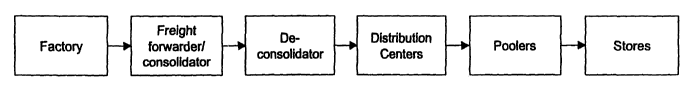
[0033] Figure 2 is a schematic representation of a preferred embodiment
of a retail organization's six-stage supply chain.
[0034] Figure 3 is an exploded view of a preferred embodiment of an
example of a RFID tag used in the system and method of the present
invention.
SUBSTITUTE SHEET (RULE 26)
-12-
CA 02419952 2003-02-20
WO 02/21424 PCT/USO1/27372
[0035] Figure 4 is an isometric view of a preferred embodiment of a
portable dock loader in accordance with the present invention.
[0036] Figure 5 is a schematic view of a preferred embodiment of a
conveyor assembly in accordance with the present invention.
[0037] Figure 6 is a front view of a preferred embodiment of a fixture in
accordance with the present invention.
[003] Figure 7 is a front view of a preferred embodiment of a wireless
device in accordance with the present invention.
DETAILED DESCRIPTION OF THE INVENTION
[0039] The present invention provides a system and method for using
RFID to optimize supply chains and improve retail operations, more
particularly the supply chain and operations of a retail organization. The
invention is also useful in preventing loss from theft by employees,
customers and others.
[0040] As used herein, RFID refers to an automatic identification
technology that uses radio frequency waves to transfer data between a
reader and a tag. As the tag enters the Radio Frequency (RF) field, the RF
signal powers the tag, or turns it on. The tag then transmits the ID and
data that has been programmed to the reader. RFID tag readers
(Interrogators) translate the radio frequency information into digital
information that can be read by software on the host computer. The
computer determines the required actions and instructs the reader, which
in turn transmits data back to the tag.
SUBSTITUTE SHEET (RULE 26)
-13-
CA 02419952 2003-02-20
WO 02/21424 PCT/USO1/27372
[0041 ] RFID interrogators (or tag readers) are available in many sizes and
shapes including portable units. All interrogators have the same basic
architecture: antenna, decoder, data converter, computer interface, and a
power supply. The tag, which varies in size and appearance, is composed
o~ a chip, which houses the "intelligence" and contains a unique
identifier number (similar to a license plate) to enable tracking; an inlay
which is the antenna, encoded within the chip to enable tracking, and the
label or other tag or packaging, which is the visual packaging of the
components. An example of one tag is shown in Figure 3.
[0042] The RFID tag may be attached to the units at origin. As the units
pass interrogators installed in appropriate locations within the retail
industry supply chain, RFID technology, when fully developed, can
provide SKU level visibility to inventory as it moves through every
process. Moreover, RFID offers readlwrite capability so users can add
data to the tags as they pass by an interrogator, enabling functions like
time stamping. RFID does not depend on orientation or line-of sight; in
other words RFID tags can be read through a carton. In addition, RFID
can identify multiple articles simultaneously.
[0043] The RFID tag can be read-only or read/write. Read only tags are
historically less expensive than read/write tags. However, a read-only
solution would potentially require substantial processing on the backend
as enormous databases would be required to store data related to every
move of each RFID tagged unit. The RFID tag read/write distances vary
depending on tag and antenna size, design and operating frequency.
SUBSTITUTE SHEET (RULE 26)
-14-
CA 02419952 2003-02-20
WO 02/21424 PCT/USO1/27372
[0044] Depending on the tag construction, an RFID system can operate in
harsh industrial or commercial environments with operating temperatures
in the range of -25C to +85C. The system can operate at various
frequencies. The currently preferred frequencies are 13.56MHz,
915MHz, and 2.45GHz. There are tradeoffs associated with these
frequencies. With regard to data reading range, a 13.56MHz system has a
range of .25 to .5 meters, a 915MHz system has a range of 3 to 5 meters,
and a 2.45GHz system has a range of .5 to 1.0 meters. The actual ranges
depend on the particular transponder used, antenna size, number of
antennas and the like. Also, the range for writing data is typically about
50% of the read data range. There are also different regulations
throughout the world, for example 13.56MHz systems are not permitted
in Japan and 915MHz are not permitted in Europe. As indicated.above,
currently both the 13.56MHz and the 2.45GHz have relatively weak
read/write ranges. The 915MHz frequency has a more attractive range but
is limited in its international acceptance to the U.S.A. and Canada only.
Finally, RFID systems can include EAS (electronic article surveillance)
capability similar in functionality to the sensormatic tag.
[0045] Major suppliers of RFID technology include Texas Instruments,
Phillips, and Intermec. RFID has defied most attempts at standardization
(13.56 MHz is in the standardization process). The goal from an industry
development perspective is to create generic tags and interrogators that
could be purchased from several vendors, thereby driving down costs.
International standaxds would allow global companies the ability to reap
SUBSTITUTE SHEET (RULE 26)
-15-
CA 02419952 2003-02-20
WO 02/21424 PCT/USO1/27372
the benefits of RFID. Several industry groups have tried to standardize
RFID and efforts continue.
[0046] For purposes of this written description, the invention will be
described in the context of a retail organization having a multiple-stage
supply chain. In the example shown in Figure 2, the supply chain
includes factories for producing products, a freight
forwardinglconsolidator, a de-consolidator, distribution centers, poolers
and stores or retail outlets. It will be appreciated by those skilled in the
art that the present invention is applicable to retail organizations having
different supply chains and also applicable to non-retail organizations.
[0047] The present invention relates to use of RFID technology that
provides advantages in each stage of the supply chain of a retail
organization. Again, the example of a supply chain is shown in
connection with Figure 2. For purposes of this description, it will be
assumed that the RFID technology is employed in a retail organization
that sells ready-to-weax garments and other items, keeping in mind that
the present invention can be applied to any supply chain regardless of the
kind of goods or services. In a preferred embodiment, an RFID tag is
associated with each ready-to-wear garment or other item. The tag may
be sewn into the garment and/or attached after the garment is
manufactured.
[0048] In the first stage of the ready-to-wear retailer's supply chain,
namely the factory, the RFID tag can be used to confirm the contents of
cartons packed by the vendor at the unit level through non-line of sight
SUBSTITUTE SHEET (RULE 26)
-16-
CA 02419952 2003-02-20
WO 02/21424 PCT/USO1/27372
scanning. RFID technology can also be used to match contents with
shipping manifests and purchase orders. Again, the RFID tag could be
any label or tag associated with the item. Examples include a hang tag, a
price tag, a pocket flasher, packaging of all kinds, boxes, or a label sewn
into the garment.
[0049] The use of the RFID technology in the factory as described above
requires tag readers at the manufacturer sites and software that provides
the ability to reconcile shipping information with the shipping manifest or
purchase order, provide exception reporting and interfacing with a
shipment tracking system.
[0050] Use of the RFID technology at the factory facilitates factory
quality assurance processes and eliminates chargebacks by identifying
actual quantities and variances up-front, prior to payment. Moreover, the
use of the RFID technology in the factory provides distribution centers
and others in the supply chain with accurate information about inbound
units. This information can be used to help prevent loss from employee,
contractor (shipper etc.) and/or customer theft. Moreover, for
international shipments, the use of RFID technology can streamline
customs processes through scanning of paperwork.
[0051] At the second stage of the ready-to-wear retailer supply chain,
namely, the freight forwarder/consolidator stage, the RFID technology
can be used to track goods received and shipped by the
forwarder/consolidator at both the carton level and the unit level. This, of
course, entails providing tag readers at forwarder/consolidator sites. Also,
SUBSTITUTE SHEET (RULE 26)
-17-
CA 02419952 2003-02-20
WO 02/21424 PCT/USO1/27372
the system must be able to reconcile shipping information with shipping
manifests/purchase orders and provide exception reporting interface with
the shipment tracking system. Software is preferably provided for this
purpose. Use of RFID technology at the freight forwarder/consolidator
site in this way facilitates vendor audits, decreases unaccounted for
inbound freight and streamlines customs paperwork. Thus, the invention
is useful in loss prevention at this stage of the supply chain.
[0052] At the third stage of the ready-to-wear retailer supply chain,
namely, the de-consolidator stage, the RFID technology can be used to
track goods received and shipped by the de-consolidator. Again, this
requires tag readers at the forwarder/consolidator sites and a system that
includes software with the ability to reconcile shipping information with
shipping manifests/purchase orders, provide exception reporting and
interface with the shipment tracking system. Use of the RFID technology
at the de-consolidator stage of the supply chain facilitates de-consolidator
audits, decreases unaccounted for inbound freight, provides distribution
centers with visibility to forthcoming receipts and improves the ability to
sort by distribution center with accuracy. The invention also aids in loss
prevention by ensuring that the product is accounted for throughout this
stage.
[0053] The RFID technology has many applications in the distribution
center (fourth) stage of the ready-to-wear retailer supply chain. To
implement these applications and achieve the associated benefits, it is
necessary to provide various tag readers (interrogators) at the distribution
SUBSTITU 1g SHEET (RULE 26)
CA 02419952 2003-02-20
WO 02/21424 PCT/USO1/27372
centers. For instance, tag readers should be provided at the distribution
receiving docks. In accordance with another aspect of the present
invention, tunnels with tag reading capability can be provided at the
distribution center receiving docks. As used herein, "tunnel" is similar to
a fixed location overhead scanner. In the preferred form the "tunnel" is a
fixed reader shaped in the form of a tunnel that a carton would pass
through so that the tags are read and identified as the carton passes
through. The system should also include software for interfacing with a
warehouse management system.
[0054] Use of the RFID technology at the distribution centers in this way
provides numerous benefits, including eliminating labor required to
manually input receipts; improving efficiency of the receiving process;
facilitating freight claims; increasing throughput; eliminating sorting of
cartons on the trailer; providing an ability to reconcile distribution center
receipt data with bills of lading and forwarder/consolidator/de-
consolidator data. The use of RFID at this stage also helps to prevent loss
due to theft. In addition, the use of the RFID technology at the
distribution center improves the value of information currently within a
warehouse management system by making it available sooner.
[0055] In addition, the RFID technology can be used to write revised data
to a unit level tag for special handling activities and to provide an ability
to identify a unit as an alternative retail outlet product. In particular, by
providing individual tags on each garment, the system can be used to
write or alter pricing data on each tag. To make such a system practical,
SUBSTITUTE SHEET (RULE 26)
-19-
CA 02419952 2003-02-20
WO 02/21424 PCT/USO1/27372
the tag reader should be able to write to multiple tags simultaneously by
broadcasting information to be written. In the preferred embodiment, the
tag reader can write to multiple tags simultaneously or write to individual
tags without writing to adjacent tags. This greatly simplifies correction or
markdown of prices and, thus, eliminates the labor required to manually
correct each ticket. In addition, this system improves the efficiencies of
the multifunction or special handling process and eliminates the manual
re-ticketing process by writing cross-reference data to the ticket for an
alternative retail store. Moreover, it is possible to electronically write
multiple prices to reflect prices in different currencies on the tag for
international shipments. Finally, use of RFID technology provides pre-
receipt visibility to the distribution center, allowing the distribution
center
to forecast and plan labor requirements and anticipate special handling
activities such as mixed cartons.
[0056] To implement this feature in a distribution center requires tag
readers or tunnels equipped with tag readers in the distribution center
multifunction area, as well as software interfaces with the overall
inventory management systems.
[0057] Yet another advantage of using RFID technology at the
distribution center stage of the supply chain is that RFID technology
provides "visibility" to carton contents without opening the carton.
Again, this requires tag readers or tunnels equipped with tag readers in the
distribution center receiving and multifunction areas as well as software
for interpreting the data read, and the interfacing with the scan and
SUBSTITU~o SHEET (RULE 26)
CA 02419952 2003-02-20
WO 02/21424 PCT/USO1/27372
warehouse management systems. The benefit of such a system is that it
reduces the labor associated with correcting incorrect contents and
downstream activities.
[0058] In addition, if tag readers are provided for distribution center
stocking and putaway associates (workers), the RFID system can also be
used for replenishment carton verification. This results in reduced labor
required for verification and reduces the amount of labor associated with
wrong product content correction in stocking. The computer system
should also interface with the warehouse management system.
[0059] In accordance with an important aspect of the present invention,
the RFID technology can also be used at the distribution center stage of
the supply chain to provide verification of pick selection. To
accommodate this, the system should include tag readers and/or tunnels
for manual pick and sorters and associated system enhancements. This
arrangement involves automated sortation equipment, e.g, a tilt tray or the
like, in which all orders for the allocation would be "batch picked,"
placed on a "trough" type of container/belt to sorter induction, inducted
directly onto trays and fixed read of units on trays. Again, "batch pick"
refers to the picking of demand allocation for all stores within the same
timeframe.
[0060] In addition, it is possible to write information directly onto the tag
at the unit level. Readers can be provided in the chutes to verify contents
and order completion or, alternatively, one fixed scan of carton contents
through a tunnel can be used. In this way, the sortation and allocation of
SUBSTITU ~1 SHEET (RULE 26)
CA 02419952 2003-02-20
WO 02/21424 PCT/USO1/27372
orders can be verified in a highly automated process. This arrangement
provides numerous benefits, including eliminating inventory adjustments,
increased accuracy and increased and improved utilization of capital. The
system can also provide significant increases in productivity.
[0061 ] - In the context of the distribution center stage of the supply chain,
RFID technology can also be used to verify manual selection. In
particular, by providing tag readers and/or tunnels for manual pick and
sorters, hand-held or wearable units can be used to assist in manually
picking or selecting units. The hand-held device reads the unit within the
pick location (by pointing at the location/units) and systematically verifies
that the user is in the right location and the product is the correct product.
For example, the system emits an audio signal, such as a beep, to inform
the user of the correct selection and indicates how many units to pick.
The user pulls the units and then goes to the remaining locations to fulfill
the store requirements. Upon pick completion, the carton is closed, sealed
and sent on a conveyer through a tunnel or RFID tag reader to verify that
the contents match the store requirements, thus guaranteeing 100%
picking accuracy audits. Cartons with errors are recorded and diverted for
correction, while others are routed to shipping. The benefits provided by
this system include significant reduction, if not total elimination, of
manual picking errors. Moreover, productivity can be increased by
eliminating the requirement to read SKU data.
[0062] In addition, by providing distribution center associates with tag
readers and making appropriate system enhancements, the RFID
SUBSTITU ~2 SHEET (RULE 26)
CA 02419952 2003-02-20
WO 02/21424 PCT/USO1/27372
technology can be used in connection with inventory control and quality
assurance. For instance, the RFID technology can be used to decrease
time associated with cycle counts and inventory audits. Moreover, the use
of RFID technology eliminates the need to open cartons to determine
contents and count (this increases picker accuracy as mentioned). In
addition, the system reduces labor associated with searching for a product
(exception mode) and reduces labor associated with mixes and wrong
content of cartons outside of receiving.
[0063] By providing tag readers, doorway portals, and tunnels equipped
with tag readers at distribution center shipping docks, it is possible to
track distribution center activity at the unit level. This eliminates the
labor required to manually scan cartons, reduces misdiverts, and improves
efficiency in the shipping process. Moreover, providing the tag readers
and tunnels at distribution center shipping docks facilitates freight claims
by providing visibility to the carton movement and contents. In
connection with bill of lading applications, it is possible to print out a
bill
9
of lading with an RFID tag so that one scan of a tag at receipt would
download the contents into the receiving system.
[0064] By providing tags and a yaxd antenna system, it is also possible to
implement a yard management system using active tags and appropriate
equipment. This, for example, could be used to identify when a truck is
on premises, where it is parked and what inventory is on the truck. This
system should be designed to interface with the ScaN and warehouse
management (WMS and TMS) systems.
SUBSTITU23 SHEET (RULE 26)
CA 02419952 2003-02-20
WO 02/21424 PCT/USO1/27372
[0065] In one embodiment of the present invention, a portal dock loader
402, as shown in Figure 4, is used as a tag reader. Portal Dock Loader
402 is preferably designed to work in conjunction with a Roller Table
404. Portal Dock Loader 402 includes a Sensing Portion 406 and a Stand
Portion 408. Sensing Portion 406 preferably includes one or more RFID
readers. These readers are preferably designed to interrogate RFID tags
that pass proximate Sensing Portion 406.
[0066] Bins 410 containing merchandise or items that include RFID tags
can be moved across Sensing Portion 406 by using the Rolling Table 404.
This permits the items of merchandise contained within Bin 410 to pass
within an appropriate distance that permits the RFID readers disposed in
Sensing Portion 406 to interrogate the RFID tags associated with the
merchandise Bin 410. The RFID readers and Sensing Portion 406 are in
communication with a Computer 412. As the readers interrogate the
RFID tags, information is transmitted to Computer 412. In this way, as
merchandise is moved down a conventional Rolling Table 404, inaccurate
assessment of the merchandise can be collected by Computer 412.
[0067] There are many uses for the Portable Dock Loader 402. Portable
Dock Loader 402 can be used to verify that certain cartons have been
placed within a trailer or have been shifted. Portable Dock Loader 402
can also be used at the receiving end to verify that certain shipping
cartons, bins or merchandise have been received by the retail store or the
next entity in the supply chain.
SUBSTITUTE SHEET (RULE 26)
-24-
CA 02419952 2003-02-20
WO 02/21424 PCT/USO1/27372
[0068] Figure 5 shows another embodiment of the present invention. A
conveyer belt 502 is used to move a Carton 504 during either loading or
unloading. As Carton 504 passes within an appropriate distance of an
RFID Reader 506, all of the RFID tags within the carton can be
interrogated. The carton can also include a single unique ID to identify
the carton. After the RFID information has been collected by Reader 506,
the information can be transmitted to another Computer 508. Similar to
the embodiment shown Figure 4, this system can determine which items
and cartons have been shipped, and if used at the receiving end, which
items have been received. This system can also associate all of the items
in the carton with the carton by using the carton's single unique identifier.
[0069] The RFID technology can also be used to track distribution
centerlcatalogue and online return receipts at the unit level. This helps in
tracking the product center finishers and restocking of products. To
implement this procedure, the users at the distribution center return area
should be provided with tag readers.
[0070] The RFID technology can also be used to increase distribution
center security, time and attendance and labor activity reporting by
providing RFID tags in associate (worker) identification badges, placing
antennas at entrance and exit locations so as to account for human
resources. Preferably, this system is interfaced with a warehouse
management system. One of the principal advantages of extensive use of
RFID technology at the distribution centers as discussed heretofore is
SUBSTITUTE SHEET (RULE 26)
- 25 -
CA 02419952 2003-02-20
WO 02/21424 PCT/USO1/27372
reduced labor effort associated with products lost within the distribution
center.
[0071] RFID technology can also be used at the third party distribution
(pooler) stage of the ready-to-wear retailer supply chain. In particular, the
RFID technology can be used to track pooler receipts at the unit level.
This will support freight claims, decrease outbound lost freight, provide
visibility to stores of forthcoming shipments, facilitate value added
services ability and provide visibility to stores turning away product. To
implement this system, it is necessary to provide RFID tag readers at the
pooler sites and software at the pooler sites to interface data collected
with inventory systems.
[0072] The present invention further contemplates wide use of RFID
technology in retail stores, the final stage of the ready-to-wear retailer
supply chain. To begin with, RFID technology can be used to track
carton contents at each store upon receipt. To implement this, RFID tag
readers should be provided at store receiving entrances. Providing this
technology decreases the time and labor required to manually track store
receipts, improves accuracy of inventory data by eliminating inaccuracies
in the manual receipt process and enables assumed receipts for direct
delivery shipments. To accommodate this, the data collection system
interfaces with inventory systems via the management tracking system
and the management tracking system reports discrepancies between bill of
lading and products received.
SUBSTITUTE SHEET (RULE 26)
-26-
CA 02419952 2003-02-20
WO 02/21424 PCT/USO1/27372
[0073] A significant advantage of using ubiquitous RFID technology
within the stores is the ability to perform perpetual inventory counts. This
can be achieved by providing hand-held readers for inventory counts or
providing readers imbedded in walls for automated inventory count. The
data received from these RFID tag readers is interfaced with the store
inventory system. This automated perpetual inventory count system
improves accuracy of inventory data, decreases the time and labor
required to manually scan individual garments and provides real-time
visibility to product gaps (for example, sizes, colors and styles) on the
sales floor that may be replenished immediately from store inventory.
[0074] Naturally, ubiquitous use of RFID technology within the store also
assists in loss prevention and security. In this context, the RFID
technology can replace existing systems such as sensor tag technology,
and thereby eliminate the labor required to attach and detach the sensor
tags and improve security at stores that do not have sensor tag
capabilities. To implement this feature, tag readers should be provided at
store exits and staff should be trained to remove or flag as sold tags after
sale.
[0075] RFID technology offers the advantage of being able to store the
identity of the person deactivating or flagging a tag. In this way, it is
possible to reduce loss due to employee theft by tracing loses to
individual employees. In contrast, sensor tags can be anonymously
removed by anyone having access to the tag removal device.
SUBSTITUTE SHEET (RULE 26)
27 _
CA 02419952 2003-02-20
WO 02/21424 PCT/USO1/27372
[0076] Use of RFID technology associated with each unit, also makes it
possible to read the contents of the customer's purchases at the point-of
sale to increase the accuracy of the checkout process, decrease time and
labor required for checkout (cashier and wrapping activities) and decrease
waiting time for the customer during checkout. To implement this feature
of the present invention, tag readers should be provided at the checkout or
cash/wrap station and the staff should be instructed in the removal andlor
flagging of the tags as sold after sale. In addition, the data read should be
interfaced with the point-of sale system.
[0077] In accordance with another aspect of the present invention, RFID
technology can be used to track assets at stores, distribution centers and
other company facilities. In the context of a retail store, for example,
RFID tags could be applied to assets, such as store fixtures, shelving, and
the like. Small items such as hand held scanners or other equipment
could also be tagged. By providing antennas (preferably fixed)
throughout the facility, the assets that are tagged can be tracked for the
purposes of planning, purchasing, management, and disposal. The use of
RFID technology in this way provides systematic visibility of the assets as
items are moved within stores, departments, cost centers, off site storage,
etc. Visibility would allow accountability and better management of
assets resulting in accurate purchasing requirements, reduced on-hand
quantities, and records to provide an accurate tax base. In the context of
fixtures used in a retail store, the visibility provided by use of RFID
SUBSTITUTE SHEET (RULE 26)
_~8_
CA 02419952 2003-02-20
WO 02/21424 PCT/USO1/27372
technology could be used to ensure that fixtures are located in
conformance with store policy.
[0078] Figure 6 shows a preferred embodiment of the present invention.
One example of a fixture used in a retail store is a shelving system 602.
Shelving system 602 includes shelves 604 and 606 that are designed to
hold merchandise. Preferably, an RFID reader is associated with shelving
system 602 and in an exemplary embodiment, shown in Figure 6, several
RFID readers are disposed proximate different collections of
merchandise. As shown in Figure 6, a first reader 608 is disposed
proximate a first collection of merchandise 610, a second reader 612 is
disposed proximate a second collection of merchandise 614, a third reader
616 is disposed proximate a third collection of merchandise 618, and a
fourth reader 620 is disposed proximate a fourth collection of
merchandise 622. The readers 608, 612, 616 and 620 are preferably
configured in a manner that permits them to interrogate and read their
associated collections but not other collections.
[0079] Once the preferred arrangement has been established, readers 608,
612, 616 and 620 may be placed in communication with a computer or
may communicate with a wireless device 702 (see Figure 7).
Communication can occur between either of these devices and shelving
system 602 using wire line or wireless communications systems.
[0080] Shelving system 602 can provide many different types of
information. Because Readers 608, 612, 616 and 620 can either
continuously or intermittently interrogate RFID tags associated with
SUBSTITU ~9 SHEET (RULE 26)
CA 02419952 2003-02-20
WO 02/21424 PCT/USO1/27372
merchandise, Shelving System 602 can provide near real time or real time
data related to merchandise disposed on Shelving System 602. Also
because the various readers are associated physically with Shelf System
602 at particular locations, Shelf System 602 can also provide information
related to where the merchandise is located within Shelf System 602. For
example if the merchandise is categorized and placed on Shelving System
602 by size, users can determine if merchandise has been improperly filed
or improperly located within Shelf System 602. The information can also
be used to determine real time inventory tracking and to determine what
items are available or not available on the retail floor.
[0081] Shelving system 602 can also be used with wireless device 702.
Wireless device 702 can be used to collect inventory information. This
inventory information can be used to determine which items are currently
on the sales floor, which items need to be replenished with stock from a
backroom, and which items need to be ordered from a distribution center.
The system can also be used to assist customers. If a customer asks for a
particular item, for example, by size and style, the characteristics of the
item can be entered into wireless device 702. The salesperson can then
use wireless device 702 to scan and interrogate RFID tags. When a tag
matching the description of the item requested by the customer is found,
wireless device 702 can provide an indication. Preferably, wireless
device 702 returns an audible indication. Wireless device 702 can also
return a series of informative beeps or any other audible tones as the
salesperson approaches the requested item. The audible tones can
SUBSTITU 3EOSHEET (RULE 26)
CA 02419952 2003-02-20
WO 02/21424 PCT/USO1/27372
increase in pitch or frequency to guide the salesperson to the requested
item.
[0082] Similarly, RFID technology can be used to track samples of
garments that a design, merchandising, production, or marketing division
may use to plan for upcoming products. As discussed above, these
samples or prototypes generally remain in-house, and the system can be
used to track the location of those samples as well as in-house shipments
of those samples. RFID tags could be applied to the samples to allow
tracking of individual units as they are moved among various
departments, divisions, and offices within the company. This would
ensure accountability, controls, and proper use or disposal of the sample
units.
[0083] Use of RFID technology at the store location also makes it
possible to better control the return process by, for example, tracking
reasons for returns back to the vendor factory level and therefore identify
specific vendor factories producing garments with quality problems such
as fit and other defects. In this way, the tags can be used to facilitate
vendor performance tracking. Again, implementing the system requires
tag readers at the cash/wrap (checkout) stations and a software interface
with the point-of sale system.
[0084] In accordance with another aspect of the present invention, RFID
technology can be used to track the fitting room traffic. For this purpose,
antennas would be placed at the entrance of fitting rooms to read the tags
of garments that are brought into the fitting room. In this way, a retailer
SUBSTITU 31 SHEET (RULE 26)
CA 02419952 2003-02-20
WO 02/21424 PCT/USO1/27372
can gather information as to what products are taken to fitting rooms - an
indication of consumer interest (at least initial interest) in some aspect
(style, color appearance etc.) of the garment. The fitting room data
collected can be correlated to sales data to provide valuable insight as to
which of the products that are tried by consumers are ultimately
purchased. There are numerous ways in which information obtained from
fitting room data collected (and e.g., correlated to sales data) can be used
for merchandising, planning and/or marketing decisions for that specific
product. For example, the data might show that a particular style of
garment is frequently tried on, but seldom purchased, which could suggest
a problem with the fit or detailing of the garment. Alternatively, the
relationship between the frequency with which a garment is tried on and
the garment's location within the store could be helpful in merchandising
products. In this way, this technology provides an in-house market
research tool.
[0085] Another possible use is to implement customer loyalty program
cards, gift cards, wish list cards and the like by providing customers with
cards equipped with RFID tags. The system could even identify
customers as they enter the store to improve customer service.
[0086] The foregoing disclosure of the preferred embodiments of the
present invention has been presented for purposes of illustration and
description. It is not intended to be exhaustive or to limit the invention to
the precise forms disclosed. Many variations and modifications of the
SUBSTITUTE SHEET (RULE 26)
-32-
CA 02419952 2003-02-20
WO 02/21424 PCT/USO1/27372
embodiments described herein will be obvious to one of ordinary skill in
the art in light of the above disclosure. The scope of the invention is to be
defined only by the claims appended hereto, and by their equivalents.
[0087] Further, in describing representative embodiments of the present
invention, the specification may have presented the method and/or
process of the present invention as a particular sequence of steps.
However, to the extent that the method or process does not rely on the
particular order of steps set forth herein, the method or process should not
be limited to the particular sequence of steps described. As one of
ordinary skill in the art would appreciate, other sequences of steps may be
possible. Therefore, the particular order of the steps set forth in the
specification should not be construed as limitations on the claims. In
addition, the claims directed to the method and/or process of the present
invention should not be limited to the performance of their steps in the
order written, and one skilled in the art can readily appreciate that the
sequences may be varied and still remain within the spirit and scope of the
present invention. Also, the invention is applicable to all forms of
products, not just apparel.
SUBSTITUTE SHEET (RULE 26)
- 33 -