Note: Descriptions are shown in the official language in which they were submitted.
CA 02420118 2003-02-12
English translation of the International Patent Applicaton
No. PCT/CHOI/00426 in the name of Stratec Medical AG
1784/PCT
25.5.2000
Device for optimising a knee endoprosthesis
The invention relates to a device permitting to determine
the optimal dimensions of individual components of a knee
endoprosthesis as claimed in the precharacterising part of
claim 1.
A device comprising a plurality of alignment and guide
appliances is known from US-A-4 524 766 PETERSEN. One of
these guides comprises an L-shaped plate having a spacer
and a foot which is aligned and fixed on the femur. This
guide serves on the one hand for guiding the cutting tool
during the anterior femoral resection and, on the other
hand, for planning the height of the posterior femoral
resection, the spacer serving for adjusting the distance to
be observed between the femur and the tibia while the knee
joint is bent. Said distance, which is to be adjusted in
accordance with the thickness of the tibial component to be
implanted, may be read form a scale present on the plate .
After that, another guide serving for the distal resection
of the femoral condyles is affixed to the tibia. Said
second guide includes a guide element which is adjustable
with respect to the height of the tibial component to be
implanted.
In this known device, the tension of the ligaments is
considered only in a bent condition of the knee joint,
during the application of the first guide. The guide for
the distal resection of the femoral condyles while the knee
CA 02420118 2003-02-12
2
is straightened is only adjustable with respect to the
tibial component, without consideration of the tension of
the ligaments.
In view of this shortcoming, it is an object of the
invention to provide a device permitting to determine, for
the entire ROM (range of motion), the optimum dimensions of
the components of a knee endoprosthesis, said device being
applicable in particular for revision purposes in knee
allo-arthroplasty.
The selectable dimensions essential for coordinated
movement include the A/P size (anterior/posterior
dimension) of the femoral component, the thickness of the
polyethylene inlay (PE inlay) of the tibial component, and
the thickness of the spacer located between the resected
femoral surface and the femoral component. In addition, it
is possible to determine the height of the resulting joint
line as well as the external rotation of the femoral
implant.
According to the invention, this object is achieved by
means of a device which shows the features of claim 1.
The device is fixed on the distal, resected surface of the
femur which serves as a surface of reference for the
device. The proximal surface of the tibia is also resected,
so as to form a further reference surface.
The device according to the invention for determining the
optimal dimensions of the components of a knee
endoprosthesis comprises an angular element affixable
distally on the femur, a first calliper located on the
CA 02420118 2003-02-12
3
posterior side (in flexion) and displaceable relative to
said angular element, and a second calliper situated on the
distal side (in extension) that is equally displaceable
relative to the angular element. The angular element
comprises a first plate having a bottom surface facing
anteriorly towards the femur, a plate longitudinal axis
extending parallel to said bottom surface and to the
longitudinal axis of the femur, a proximal, first end
portion and a second end portion intersecting the plate
IO longitudinal axis and arranged distally to the femur, and a
second plate extending perpendicularly to said bottom
surface having a central axis extending perpendicularly to
the plate longitudinal axis, an inner side capable of being
brought to rest against the resected end face of the femur,
and a bottom end portion arranged posteriorly to the femur.
The first calliper has a first bearing surface extending
substantially parallel to the bottom surface and designed
to rest against the proximal, resected tibial plateau when
the knee joint is bent, it is displaceable parallel to the
central axis and is releasably fastenable on the second
plate. The second calliper has a second bearing surface
extending substantially parallel to the inner surface and
designed to rest against the proximal, resected tibial
plateau when the knee joint is straightened, it is
displaceable parallel to the plate longitudinal axis and is
releasably fastenable on the first plate.
In the preferred embodiment of the device according to the
invention, said device comprises a first inlay which is
arranged between the posterior, bottom end portion of the
second plate and the first calliper in such a way as to be
displaceable coaxially to the central axis and is
releasably fastenable on the second plate. A second inlay
CA 02420118 2003-02-12
4
is arranged between the distal, second end portion of the
first plate and the second calliper in such a way as to be
displaceable coaxially to the plate longitudinal axis and
is releasably fastenable on the first plate. The inlays are
embodied in such a way that the callipers are displaceable
relative to the inlays in a direction parallel to the
central axis and to the plate longitudinal axis,
respectively.
In a further embodiment of the device according to the
invention, the two callipers comprise positioning means
which are arranged on a straight line extending parallel to
the central axis and the plate longitudinal axis,
respectively, and are spaced apart from one another in
axial succession by the distances ai, whereby the bearing
surfaces of the callipers are fastenable at defined
distances (Ai = E a~; j - 1 to N) relative to the inlays.
Furthermore, both inlays may be provided with positioning
means which are equally arranged on a straight line
extending parallel to the plate longitudinal axis and to
the central axis, respectively, and are spaced apart from
one another in axial succession by the distances bi for the
second inlay and by the distances q for the first inlay,
whereby the inlays are fastenable at the defined distances
(Bi - E b~; j - 1 to M) and (Ci - E c~; j - 1 to Q) ,
respectively, relative to the plates.
The desired amounts for the relevant values (A;, Bi or Ci)
can easily be read on the device by the surgeon. For this
purpose, marks indicating the different distances may be
made on the device. The crucial ligaments are not taken
CA 02420118 2003-02-12
into consideration by the device as the latter is primarily
intended to be usable for revision purposes.
Preferably, the positioning means are grooves which are
5 formed in the callipers and in the inlays in such a way
that screws insertable into the plates may be made to
releasably engage with the grooves.
The adjustment of the distances Ai, Bi, and CI on the device
permits to simultaneously determine the A/P size of the
femoral component by adjusting the distance Ci, the
thickness of the polyethylene (PE) inlay of the tibial
component by adjusting the distances Ai, the thickness of
the spacer for the femoral component by adjusting the
distance Bi , as well as the height of the resulting j oint
line and the external rotation of the femoral implant by
checking the tension of the ligaments of the knee when the
knee is bent (with the femur and the tibia forming an angle
of 90 degrees between each other) and when the knee is
straightened (with the femur and the tibia forming an angle
of 0 degrees between each other).
These values are established before the A/P cuts and the
oblique cuts are realised on the femur.
In a preferred improvement of the invention, the distances
Ai correspond to the different, standardised thicknesses of
the inlay (PE-inlay) of the tibial component, the distances
Bi correspond to the different, standardized thicknesses of
the spacer, and the distances Ci permit to adjust the
different, standardised A/P sizes of a femoral component of
the knee endoprosthesis.
CA 02420118 2003-02-12
6
The advantages of the device according to the invention
consist in the possibility to optimise the thickness of the
inlay, the thickness of the spacer and the A/P size of the
femoral component by an adequate adjustment of the movable
parts of the device in such a way that the tension of the
ligaments corresponds to that of a natural knee joint.
In the following, the invention and improvements of the
invention will be illustrated in greater detail with
reference to the partially diagrammatic representations of
several embodiments.
In the drawings:
Fig. 1 is a perspective, exploded view of one embodiment of
the device according to the invention;
Fig. 2 shows a view of the device according to the
invention represented in Fig. 1;
Fig. 3 shows a perspective view of a knee endoprosthesis;
and
Fig. 4 is a sectional view of the embodiment of the device
according to the invention shown in Figs. 1 and 2.
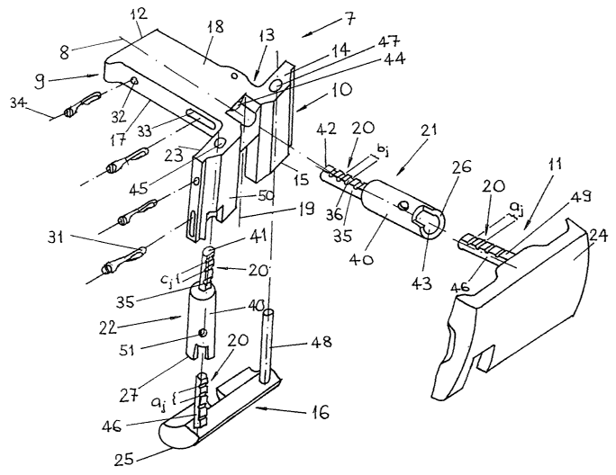
Fig. 1 shows a preferred embodiment of the device according
to the invention. This device comprises essentially an
angular element 7 which consists of a first plate 9
arranged anteriorly on the femur 5 (Fig. 2) and having a
longitudinal axis 8, and, arranged at a right angle
thereto, of a second plate 10 arranged distally on the
femur 5 (Fig. 2) and having a central axis I9 extending
CA 02420118 2003-02-12
7
perpendicularly to the first plate 9, a first calliper 16
arranged posteriorly on the second plate 10 in such a way
as to be displaceable, and releasably fastenable, parallel
to the central axis 19, and a second calliper 11 arranged
distally on the angular element 7. The first plate 9
comprises, posteriorly, a bottom surface 17 and,
anteriorly, a top surface 18, a first end portion 12
proximally intersecting the plate longitudinal axis 8, and
a second end portion 13 distally intersecting the plate
longitudinal axis 8. The second plate 10 comprises
anteriorly a top end portion 24, posteriorly a bottom end
portion 15, and a substantially planar, inner side 23
adjoining the second end portion 13 so that the angular
element 7 may be connected to the femur 5 in such a way
that the inner side 23 may be brought to rest against the
distal end face 28 of the femur and the first plate 9 is
arranged anteriorly to the femur 5 with its longitudinal
axis 8 extending parallel to the longitudinal axis of the
femur 5. The angular element 7 is affixed to the femur 5
using an intramedullary rod 30 (Fig. 2) which is insertable
into the intramedullary canal of the femur 5 in such a way
as to be freely turnable therein. The first calliper 16
includes a first bearing surface 25 which extends
substantially parallel to the bottom surface 17 of the
first plate 9 and which may be brought to bear against the
tibial plateau 29 when the knee joint is bent. The second
calliper 11 is arranged on the second end portion 13 of the
first plate 9 in such a way as to be displaceable, and
releasably fastenable, parallel to the plate longitudinal
axis 8, and includes a second bearing surface 24 which
extends substantially parallel to the inner side 23 of the
second plate 10 and may be brought to rest against the
tibial plateau 29 when the knee joint is straightened.
CA 02420118 2003-02-12
8
Furthermore, the device comprises an inlay 22 which has a
bottom end face 27 facing the first calliper 16, which is
arranged coaxially_to the central axis 19 so as to be
displaceable between the bottom end portion 15 of the
second plate 10 and the first calliper 16, and which is
releasably fastened to the second plate 10, so that the
inlay 22 is displaceable posteriorly relative to the second
plate 10 while the first calliper 16 is displaceable
relative to the first inlay 22 and, consequently, to the
second plate 10.
By analogy, between the second end portion 13 of the first
plate 9 and the second calliper 11, a second inlay 21 is
inserted, which is provided with an anterior end face 26
facing the second calliper 11, and is arranged in such a
way as to be displaceable coaxially to the plate
longitudinal axis 8 and releasably fastenable to the first
plate 9, so that the second inlay 21 is distally
displaceable relative to the first plate 9 and the second
calliper 11 is displaceable relative to the first inlay 22.
On the side opposite to the end face 27, the first inlay 22
is provided with a top end portion 41 and comprises,
extending between the bottom end face 27 and the top end
portion 41 and arranged axially adjacent to one another, a
sleeve 40 and a pin 35. The sleeve 40 adjoins the bottom
end face 27 and is provided with a sleeve bore 43 which is
open towards the bottom end face 27. By analogy, the second
inlay 21 has a posterior end portion 42 arranged on the
side opposite to the anterior end face 26 and comprises,
extending between the anterior end face 26 and the
posterior end portion 42 and arranged axially adjacent to
CA 02420118 2003-02-12
9
one another, a sleeve 40 and a pin 35, the sleeve 40
adjoining the anterior end face 26 and the sleeve bore 43
being open towards the anterior end face 26. For receiving,
by way of axial displacement, the second inlay 21, the
first plate 9 includes a first guide bore 44 extending
coaxially to the plate longitudinal axis 8, whereas the
second plate 10 comprises a second guide bore 45 extending
parallel to the central axis 19 for receiving, by way of
axial displacement, the first inlay 22, and comprises, in
addition, a further bare 47, equally extending parallel to
the central axis 19, for receiving, by way of axial
displacement, a peg 48 connected to the first calliper 11.
On their sides facing the first and the second bearing
surfaces 25;24, respectively, the first and second
callipers 16;11 are each provided with a guide bolt 46
which may be received, by way of axial displacement, in the
sleeve bores 43, so that the first plate 9, the second
inlay 21, and the second calliper 11 are axially
telescopable relative to the plate longitudinal axis 8. On
the other hand, the first inlay 22 and the first calliper
16 are axially telescopable relative to the central axis
19.
The second calliper 11 further comprises positioning means
20 which are arranged on a straight line extending parallel
to the plate longitudinal axis 8 and are spaced apart from
each other in axial succession by the distances aj. By
means of these positioning means 20, the second bearing
surface 24 of the second calliper 11 may be fixed at the
defined distances (Ai - E a~; j - 1 to N) relative to the
anterior end face 26 of the second inlay (Fig. 2).
CA 02420118 2003-02-12
By analogy, the first calliper 16 comprises positioning
means 20 which are arranged on a straight line extending
parallel to the central axis 19 and are axially spaced
apart from each other by the distances a~, whereby the
5 first bearing surface 25 of the first calliper 16 may be
fixed at the defined distances (ai - E a~; j - 1 to N)
relative to the bottom end face 27 of the first inlay 22
(Fig. 2).
10 The pins 35 provided on the first and second inlays 22;21,
as well as the guide bolts 46 provided on the first and
second callipers 16; 11 have a cross section shaped in the
form of a segment of a circle, the flats 49 facing towards
the top surface 18 of the first plate 9 and towards the
outer side 50 of the second plate 10, respectively. Grooves
36 which are sunk into these flats 49 form the positioning
means 20 and extend crosswise relative to the plate
longitudinal axis 8 and to the central axis 19,
respectively. The axial arresting of the first and second
inlays 22;21 relative to the first and second plates 9;10,
respectively, is realised by means of location pins 31
which are lodged in an axially displaceable manner within
the first and second plates 9;10 by means of first
transverse bores 32 having bore axes 34 extending crosswise
to the plate longitudinal axis 8 and to the central axis
19, respectively, said location pins being capable of
engaging with the grooves 36 formed i_n the pins 35. The
axial arresting of the first and second callipers 16;11
relative to the first and second inlays 22;21 is equally
realised by means of such location pins 31 which are lodged
in an axially displaceable manner within second transverse
bores 51 formed in the first and second inlays 22;21 and
may be brought to engage with the grooves 36 formed in the
CA 02420118 2003-02-12
11
guide bolts 46. In order to assure that the first and
second inlays 22;21 with arrested first and second
callipers 6;11 remain nonetheless displaceable relative to
the first and second plates 9;10, the first and second
plates 9;10 are provided with elongate holes 33 having
their longitudinal dimensions parallel to the plate
longitudinal axis 8 and to the central axis 19,
respectively, and which serve for receiving the location
pins 31.
The distances A correspond to the different, standardised
thicknesses of an inlay 2 of the tibial component of a knee
endoprosthesis (Fig. 3).
The second inlay 21 equally comprises positioning means 20
which are arranged on a straight line extending parallel to
the plate longitudinal axis 8 and are spaced apart from one
another in axial succession by the distances b. Thus, the
anterior end face 26 of the second inlay 21 is adjustable
at the defined distances (B = E b; j - 1 to M) relative to
the second end portion 13 of the first plate 9. These
distances B correspond to the different, standardised
thicknesses of a spacer 3 for the femoral component 1 of a
knee endoprosthesis.
By analogy, the first inlay 22 comprises positioning means
20 which are arranged on a straight line extending parallel
to the central axis 19 and are spaced apart from one
another in axial succession by the distances c~. Thus, the
bottom end face 27 of the first inlay 22 may be fixed at
the defined distances (Ci - E c~; j - 1 to Q) relative to
the bottom end portion 15 of the second plate 10, the
CA 02420118 2003-02-12
12
distances Ci corresponding to the different, standardised
A/P sizes 30 of a femoral component 1 of a knee
endoprosthesis.
Fig. 3 shows an embodiment of a knee endoprosthesis
represented together with a femur 5 and a tibia 6. The knee
endoprosthesis is composed of a femoral component 1 with a
selectable A/P size 30 (anterior/posterior size), a spacer
3 capable of being mounted between the femur 5 and the
IO femoral component 1, a tibial component 4 and an inlay 2
located between the tibial component 4 and the femoral
component 1. The thickness ai of the inlay 2, measured in
an axial direction with respect to the longitudinal axis of
the bone, the distance C; of the spacer 3, equally measured
in an axial direction with respect to the longitudinal axis
of the bone, and the anterior/posterior size 30 of the
femoral component l, measured in an anterior/posterior
direction perpendicularly to the longitudinal axis of the
bone, represent the dimensions of the knee endoprosthesis
which may be determined with the aid of the device
according to the invention.
Fig. 4 shows an example of one of the location pins 31
which is lodged in the first transverse bore 32 of the
second plate 10 in such a way as to be displaceable
coaxially to the bore axis 34. In the bottom end portion of
the first transverse bore 32, a spring 39 is inserted which
presses the location pin 31 against the pin 35. The
location pin 31 is provided with a recess 38 including a
cam 37 protruding from this recess 38. The cam 37 extends
only over part of the axial length of the recess 38. In a
first position, the location pin 31 is urged against the
pin 35 by the elastic force of the spring 39, so that the
CA 02420118 2003-02-12
13
recess 38 which partially surrounds the pin 35 on its
periphery is axially displaced to such an extent relative
to the pin 35 that the cam 37 engages with one of the
grooves 36. In a second position, into which the location
pin 31 may for example be axially pushed by hand against
the elastic force of the spring 39, the recess 38 which
partially surrounds the pin 35 is displaced to such an
extent relative to the pin 35 that the cam 37 is axially
released from the groove 36 with respect to the bore axis
34 and that the pin 35 is displaceable parallel to the
central axis 19. The embodiment of the location pin 31
including a recess 38, a cam 37, and a spring 39, as set
forth in connection with the present example is also valid
for the other location pins 31 used with the device
according to the invention (Fig. 1).