Language selection

Search

Patent 2420541 Summary

Third-party information liability

Some of the information on this Web page has been provided by external sources. The Government of Canada is not responsible for the accuracy, reliability or currency of the information supplied by external sources. Users wishing to rely upon this information should consult directly with the source of the information. Content provided by external sources is not subject to official languages, privacy and accessibility requirements.

Claims and Abstract availability

Any discrepancies in the text and image of the Claims and Abstract are due to differing posting times. Text of the Claims and Abstract are posted:

  • At the time the application is open to public inspection;
  • At the time of issue of the patent (grant).
(12) Patent: (11) CA 2420541
(54) English Title: SUCTION PUMP
(54) French Title: POMPE ASPIRANTE
Status: Deemed expired
Bibliographic Data
(51) International Patent Classification (IPC):
  • A61M 1/00 (2006.01)
(72) Inventors :
  • GRETER, ANDY (Switzerland)
  • KUENZLER, HANSRUEDI (Switzerland)
  • SILVER, BRIAN H. (United States of America)
(73) Owners :
  • MEDELA AG (Switzerland)
(71) Applicants :
  • MEDELA AG (Switzerland)
(74) Agent: ROBIC
(74) Associate agent:
(45) Issued: 2009-01-20
(86) PCT Filing Date: 2001-08-28
(87) Open to Public Inspection: 2002-03-07
Examination requested: 2006-06-29
Availability of licence: N/A
(25) Language of filing: English

Patent Cooperation Treaty (PCT): Yes
(86) PCT Filing Number: PCT/CH2001/000524
(87) International Publication Number: WO2002/017992
(85) National Entry: 2003-02-25

(30) Application Priority Data:
Application No. Country/Territory Date
00118590.9 European Patent Office (EPO) 2000-08-28

Abstracts

English Abstract


The inventive suction pump is essentially comprised of three separate pump
parts, namely of a drive unit located inside a main casing (1), of a
collecting reservoir (8) and of a valve block (6), which is arranged directly
between the casing (1) and reservoir, whereby these parts can be easily
coupled to one another in a manner that enables them to be detached.


French Abstract

L'invention concerne une pompe aspirante comprenant essentiellement trois parties séparées, notamment une unité d'entraînement montée dans un carter principal (1), une cuve collectrice (8) et un mécanisme de distribution et de régulation (6) monté directement entre le carter (1) et la cuve. Ces parties sont interconnectées de manière aisée à détacher.

Claims

Note: Claims are shown in the official language in which they were submitted.


5

WHAT IS CLAIMED IS:


1. Suction pump for medical applications, specifically pump for sucking off
secretions, with a collecting reservoir for material to be sucked off, a valve
block
for a alternating connection of a pump chamber through corresponding valves
for a production of a vacuum in latter or a blowing off circuit respectively,
depending from the direction of movement of a membrane pump plunger, and a
driving unit of the membrane plunger, characterized in that collecting
reservoir,
valve block and driving unit are designed as separate pump parts which for the

operation of the pump can be releasable coupled to each other, whereby the
valve block comes to lie directly between collecting reservoir and driving
unit
and the membrane pump plunger located in the driving unit cooperates at a
front
end of the plunger with a membrane which is arranged sealed against the inside

of the driving unit, is however exposed towards the environment, and the pump
chamber is located between valve block and driving unit and is defined by a
wall
of the valve block provided with the valves and a wall of the driving unit or
membrane, respectively.


2. The suction pump according to claim 1, characterized in that the
releasable joined pump parts are arranged on a common plate.


3. The suction pump according to claim 1 or 2, characterized in that the
releasable connection between the pump parts proceeds through plug in and/or
snap on connections.


4. The suction pump according to one of the claims 1 to 3, characterized in
that the valve block communicates in the assembled state with two
compartments separated from each other, namely a first compartment which at
the one hand can be connected to the collecting reservoir and at the other
hand
can be connected through a suction valve to the pump chamber, as well as a


6


second compartment, which connects the pump chamber through a outlet valve
to the blow-off circuit.


5. The suction pump according to claim 1, wherein the pump parts can be
easily assembled and again disassembled for cleaning purposes without any
special knowledge and without hose connections.


6. The suction pump according to claim 1, wherein the driving unit
comprises a main housing, a pump drive and possibly an accumulator, wherein
the main housing is plugged onto a base plate.


7. The suction pump according to claim 1, wherein the valve block
comprises a vacuum setting button for adjustment of the desired vacuum.


Description

Note: Descriptions are shown in the official language in which they were submitted.


CA 02420541 2008-05-22
1

SUCTION PUMP

The present invention relates to a suction pump for medical applications,
specifically a pump for sucking off secretions, with a collecting reservoir
for
material to be sucked off, a valve block for a alternating connection of the
pump
chamber through corresponding valves to the collecting reservoir for a
production of a vacuum in latter or a blowing off conduit respectively,
depending
from the direction of movement of a membrane pump plunger, and a driving unit
of the membrane pump plunger.

The nowadays known suction pumps of this kind have the drawback, that except
the
demountable collecting reservoir the cleaning ofthe other pump parts is
complicated
and difficult, because specifically areat care must be taken in order to
prevent a liquid
(washing liquid, rests of secretion) from penetrating into the driving unit.

Object of the present invention has been to provide a suction pump which
having a as
simple as possible design can be easily assembled and again disasseinbled for
cleaning
purposes without any special knowledge (no hose connections). The manipulating
shall
be as easy as possible (one button On/Ofl) and the collecting reservoir shall
be able to
be washed after its emptying in the washing machine, e.g. a disllwasher. Also
the other
pump parts, that is valve block and driving unit, which due to a special
overflow design
of the collecting reservoir are not subject to a contamination, shall if
necessary be able
to be washed without a detrimental influence on their function properties.

This object is solved by a suction pump for medical applications, specifically
pump for sucking off secretions, with a collecting reservoir for material to
be
sucked off,a valve block for a alternating connection of a pump chamber
through
corresponding valves for a production of a vacuum in latter or a blowing off
circuit respectively,_depending from the direction of movement of a membrane
pump plunger, and a driving unit of the membrane plunger, characterized in
that
collecting reservoir, valve block and driving unit are designed as separate
pump
parts which for the operation of the pump can be releasable coupled to each


CA 02420541 2008-05-22
la

other, whereby the valve block comes to lie directly between collecting
reservoir
and driving unit and the membrane pump plunger located in the driving unit
cooperates at a front end of the plunger with a membrane which is arranged
sealed against the inside of the driving unit, is however exposed towards the
environment, and the pump chamber is located between valve block and driving
unit and is defined by a wall of the valve block provided with the valves and
a
wall of the driving unit or membrane, respectively.

The various pump parts are, thereby, preferably arranged at a conunon base
plate by
means of plug in and/or snap on connections.

In the following, the invention is explained somewllat niore ul detail with
reference to a
embodinient illustrated in the drawing.

There is shown in:


CA 02420541 2003-02-25
2

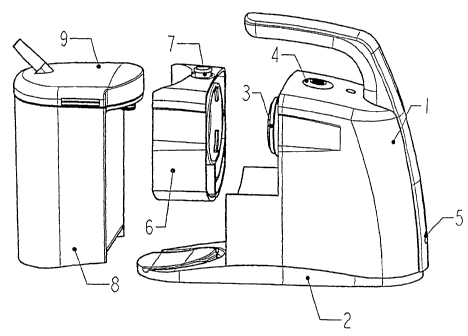
Fig. I purely schematically a suction pump to be formed of three main parts;
Fig. 2 a suction pump assembled from the three main parts according to Fig. 1;
and

Fig. 3 a longitudinal section through the suction pump according to Fig. 2 on
a
somewhat enlarged scale.

Figure 1 of the drawing illustrates the three main parts of the suction pump,
namely the
main housing 1 with the mounted motor, pump drive and possibly a accumulator
(these
mounting parts are illustrated in Fig. 3), which is plugged onto a base plate
2, whereby
the membrane 3 of a membrane pump plunger (see Fig. 3), the main switch
4(On/Off)
as well as a electric power connection 5 are illustrated, furthermore a valve
block 6 with
overflow chamber (Fig. 3) and vacuum setting button 7 (e.g. two positions) and
finally a
reusable collecting reservoir 8 with cover 9 placed thereupon.

The main parts of the suction pump illustrated in Figure 1 can be assembled
easily
(plugging and snap on connections) and obviously be in the same manner easily
disassembled (for cleaning purposes). The valve block 6 cones, thereby, to lie
directly
between the main housing 1 and the exchangeable collecting reservoir 8 such as
illustrated by Figure 2. The main parts are preferably plugged onto the base
plate 2.

The concept of the design in accordance with the invention can be best seen at
the cross
section according to Figure 3.

In the main housing 1 a electromotor 10 (e.g. a 12V- direct current motor) is
flanged
onto a plate 11 and serves for the driving of an eccentric 12 (with additional
unbalance
13). The eccentric 12 serves as drive for the pump plunger 14 which is
provided with a
membrane 15 (e.g. a spray coated membrane) and serves in operation for the
production
of a desired vacuum. A accumulator 16 is also present in the main housing 1
which is
plugged onto a base plate 2. A power supply from the outside proceeds through
a


CA 02420541 2003-02-25
~
J

connecting bushing 17 (12V - direct current for the supply of the accumulator
16 or for
a direct supply of the motor 10). Finally, a press button switch 18 (On/Off)
is arranged
on the upper side of the housing 18.

Also plugged onto the base plate 2, at the left side, is the exchangeable,
reusable
collecting reservoir 8 for the material to be sucked off (e.g. secretion) with
reservoir
cover 9. The material to be sucked off by vacuum produced in the reservoir 8
enters the
reservoir 8 through a conduit hose (not illustrated) to be connected to the
stub 19.

As third separate main part a valve block 6 is inserted between the collecting
reservoir 8
and main housing 1, whereby it is coupled releasable by suitable connectors to
the
reservoir 8 and the housing 1. Because the actual pump chamber 20 is located
between
the valve block 6 and the membrane pump plunger 14 with the membrane 15
located at
its front end arranged in the main chamber 1, this chamber 20 is connected to
a device
for setting the desired vacuum (vacuum setting button 21 with e.g. two
different
positions).

Automatically operating valves 23 and 24, resp. are arranged in a wall 22 of
the valve
block 6: When the plunger 14 and membrane 15, resp. moves in the direction R,
a
vacuum is produced and air is sucked out of the reservoir 8 through the valve
23 which
opens (in order to produce a vacuum in the receiving reservoir). At the
pushing
movement of the plunger 14 and the membrane 15, resp. in the direction L the
valve 23
closes and the air sucked into the pump chamber 20 is expelled through the
valve 24
which opens, this into a chamber 26 closed by means of a cover 25 which is in
communication with the environment through free channels between the pump
parts
which are connected to each other (Off).

The connection between coilecting reservoir 8 and valve block 6 proceeds
through a
stub 27 located at a high spot which in a emergency forms also a overflow for
the
reservoir 8. Due to this specific design, liquid which possibly enters the
valve block 6
can not detrimentally influence the driving unit of the pump.


CA 02420541 2003-02-25
4

The individual pump parts 1, 6 and 8 can be assembled and disassembled in a
easiest
way which renders their cleaning to be very easy and without any problems
(collecting
reservoir 8 and valve block can be cleaned in a dishwasher).

Representative Drawing
A single figure which represents the drawing illustrating the invention.
Administrative Status

For a clearer understanding of the status of the application/patent presented on this page, the site Disclaimer , as well as the definitions for Patent , Administrative Status , Maintenance Fee  and Payment History  should be consulted.

Administrative Status

Title Date
Forecasted Issue Date 2009-01-20
(86) PCT Filing Date 2001-08-28
(87) PCT Publication Date 2002-03-07
(85) National Entry 2003-02-25
Examination Requested 2006-06-29
(45) Issued 2009-01-20
Deemed Expired 2019-08-28

Abandonment History

There is no abandonment history.

Payment History

Fee Type Anniversary Year Due Date Amount Paid Paid Date
Application Fee $300.00 2003-02-25
Registration of a document - section 124 $100.00 2003-06-12
Maintenance Fee - Application - New Act 2 2003-08-28 $100.00 2003-08-21
Maintenance Fee - Application - New Act 3 2004-08-30 $100.00 2004-08-04
Maintenance Fee - Application - New Act 4 2005-08-29 $100.00 2005-08-02
Maintenance Fee - Application - New Act 5 2006-08-28 $200.00 2006-06-20
Request for Examination $800.00 2006-06-29
Maintenance Fee - Application - New Act 6 2007-08-28 $200.00 2007-06-26
Maintenance Fee - Application - New Act 7 2008-08-28 $200.00 2008-06-30
Final Fee $300.00 2008-11-06
Maintenance Fee - Patent - New Act 8 2009-08-28 $200.00 2009-08-13
Maintenance Fee - Patent - New Act 9 2010-08-30 $200.00 2010-08-12
Maintenance Fee - Patent - New Act 10 2011-08-29 $250.00 2011-08-11
Maintenance Fee - Patent - New Act 11 2012-08-28 $250.00 2012-08-16
Maintenance Fee - Patent - New Act 12 2013-08-28 $250.00 2013-08-19
Maintenance Fee - Patent - New Act 13 2014-08-28 $250.00 2014-08-18
Maintenance Fee - Patent - New Act 14 2015-08-28 $250.00 2015-08-17
Maintenance Fee - Patent - New Act 15 2016-08-29 $450.00 2016-08-16
Maintenance Fee - Patent - New Act 16 2017-08-28 $450.00 2017-08-14
Owners on Record

Note: Records showing the ownership history in alphabetical order.

Current Owners on Record
MEDELA AG
Past Owners on Record
GRETER, ANDY
KUENZLER, HANSRUEDI
SILVER, BRIAN H.
Past Owners that do not appear in the "Owners on Record" listing will appear in other documentation within the application.
Documents

To view selected files, please enter reCAPTCHA code :


To view images, click a link in the Document Description column. To download the documents, select one or more checkboxes in the first column and then click the "Download Selected in PDF format (Zip Archive)" or the "Download Selected as Single PDF" button.

List of published and non-published patent-specific documents on the CPD .

If you have any difficulty accessing content, you can call the Client Service Centre at 1-866-997-1936 or send them an e-mail at CIPO Client Service Centre.


Document
Description 
Date
(yyyy-mm-dd) 
Number of pages   Size of Image (KB) 
Abstract 2003-02-25 2 73
Claims 2003-02-25 1 44
Drawings 2003-02-25 2 83
Description 2003-02-25 4 143
Representative Drawing 2003-02-25 1 14
Cover Page 2003-04-29 1 38
Description 2008-05-22 5 167
Claims 2008-05-22 2 60
Drawings 2008-05-22 2 76
Representative Drawing 2009-01-07 1 14
Cover Page 2009-01-07 1 40
Cover Page 2009-03-17 2 84
PCT 2003-02-25 6 200
Assignment 2003-02-25 5 128
Correspondence 2003-04-25 1 22
Assignment 2003-06-12 2 76
Fees 2003-08-21 1 28
PCT 2003-02-26 2 90
Fees 2004-08-04 1 33
Fees 2005-08-02 1 23
Fees 2006-06-20 1 32
Prosecution-Amendment 2006-06-29 1 29
Fees 2007-06-26 1 41
Prosecution-Amendment 2007-11-26 2 68
Prosecution-Amendment 2008-05-22 11 374
Fees 2008-06-30 1 41
Correspondence 2008-11-06 2 57
Correspondence 2009-01-28 2 51
Prosecution-Amendment 2009-03-17 2 58
Correspondence 2010-08-10 1 44