Note: Descriptions are shown in the official language in which they were submitted.
CA 02421090 2003-03-19
1
SPECIFICATI021
Picture Coding Device, Picture Coding Method, Picture Decoding
Device, Picture Decoding Method, And Providing Medium
Technical Field
The present invention relates to an image encoder, an
image encoding method, an image decoder, an image decoding
method, and distribution media. vMore particuiarl.y, the
,invention relates to an image encodes°, an image encoding
method, an image decoder, an image decoding method, and
distribution media suitable for use, for example, in the
case where dynamic image data is recorded on storage media,
such as a magneto-optical disk, magnetic tape, etc., and
also the recorded data is regenerated and displayed on a
display,.or in the case where dynamic image data is
transmitted from a transmitter side t:o a receiver side
through a transmission path and, on the receiver side, the
received dynamic image data is displayed or it is edited and
recorded, as in videoconference systems, -crideophone systems,
broadcasting equipment, and multimedia data base.retrieval
systems.
Background Art
1
CA 02421090 2003-03-19
For instance, as in videoconference systems and
videophone systems, in systems which transmit dynamic image
data to a remote place, image data is compressed and encoded
by taking advantage of the line correlation and interframe
correlation in order to take efficient advantage of
transmission paths.
As a representative high-efficient dynamic image
encoding system, there is a dynamic image encoding system
for storage media, based on Moving Picture Experts Group
(MPEG) standard. This MPEG standard has been discussed by
the International Organization for Standardization (ISO)-
IEC/JTC1/SC2/WG11 and has been proposed as a proposal fox
standard. The MPEG standard has adopted a hybrid system
using a combination of motion compensative predictive coding
and discrete cosine transform (DCT) coding.
The MPEG standard defines some profiles and levels in
order to support a wide range of applications and functions.
The MPEG standard is primarily based on Main Profile at Main
level (MP@ML) .
Figure 1 illustrates the constitution example of an
MP@ML encoder in the MPEG standard system.
Image data to be encoded is input to frame memory 31
and stored temporarily. ~. motion vector detector 32 reads
out image data stored in the frame memory 31, for example,
at a macroblock unit constituted by 16 ( 16 pixels, and
2
CA 02421090 2003-03-19
detects the motion vectors.
Here, the motion vector detector 32 processes the image
data of each frame as any one of an intracoded picture (I-
picture), a forward predictive-coded picture (P-picture), or
a bidirectionally predictive-coded picture (B-picture).
Note that how images of frames input in sequence are
processed as I-, P-, and B-pictures h.as been predetermined
(e.g., images are processed as I-picture, B-picture, P-
picture, B-picture, P-picture, ..., B-picture, and P-picture
in the recited order).
That is, in the motion vector detector 32, reference is
made to a predetermined reference frame in the image data
stored in the frame memory 31, and a-small block of 16
pixels ( 16 lines (macroblock) in the current frame to be
encoded is matched with a set of blocks of the same size in
the reference frame. With block matching, the motion vector
of the macroblock is detected.
Here, in the MPEG standard, predictive modes for an
image include four kinds: intracoding, forward predictive
Coding, backward predictive coding, alld bidirectionally
predictive coding. An I-picture is encoded by intracoding.
A P-picture is encoded by either infra coding or forward
predictive coding. A B-picture is encoded by either
intracoding, forward predictive coding, backward predictive
coding, or bidirectionally predictive coding.
3
CA 02421090 2003-03-19
That is, the motion vector detector 32 sets the
intracoding mode to an I-picture as a predictive mode. In
this case, the motion vector detector. 32 outputs the
predictive mode (intracoding mode) to a variable word length
coding (VLC) unit 36 and a motion compensator 42 without
detecting the motion vector.
The motion vector detector 32 also performs forward
prediction for a P-picture and detects the motion vector.
Furthermore, in the motion vector detector 32, a prediction
error caused by performing forward prediction is compared
with dispersion, for example, of macroblocks to be encoded
(macroblocks in the P-picture). As a result of the
comparison, when the dispersion of the macroblocks is
smaller than the prediction error, the motion vector
detector 32 sets an intracoding mode as the predictive mode
and outputs it to the VLC unit 36 and motion compensator 42.
Also, if the prediction error caused by performing forward
prediction is smaller, the motion vector detector 32 sets a
forward predictive coding mode as the predictive mode. The
forward predictive coding mode, along with the detected
motion vector, is output to the VLC unit 36 and motion
compensator 42.
The motion vector detector 32 further performs forward
prediction, backward prediction, and bidirectional
prediction for a B-picture and detects the respective motion
4
CA 02421090 2003-03-19
vectors. Then, the motion vector detector 32 detects the
minimum error from among the prediction errors in the
forward prediction, backward prediction, and bidirectional
prediction (hereinafter referred to the minimum prediction
error as needed), and compares the minimum prediction error
with dispersion, far example, of macroblocks to be encoded
(macroblocks in the B-picture). As a result of the
comparison, when the dispersion of the macroblocks is
smaller than the minimum prediction error, the motion vector
detector 32 sets an intracoding mode as the predictive mode
and outputs it to the VLC unit 36 and motion compensator 42.
Also, if the minimum prediction error is smaller, the motion
vector detector 32 sets as the predictive mode a predictive
mode in which the minimum prediction error was obtained.
The predictive mode, along With the corresponding motion
vector, is output to the VLC unit 36 and motion compensator
42.
If the motion compensator 42 receives both the
predictive mode and the motion vector from the motion vector
detector 32, the motion compensator 42 will read out the
coded and previously locally decoded image data stored in
the frame memory 43 in accordance with the received
predictive mode and motion vector. This read image data is
supplied to arithmetic units 33 and 4U as predicted image
data.
CA 02421090 2003-03-19
The arithmetic unit 33 reads fz~om the frame memory 31
the same macroblock as the image data read out from the
frame memory 31 by the motion vector detector 32, and
computes the difference between the tnacroblock and the
predicted image which was supplied from the motion
compensator 42. This differential value is supplied to a
DCT unit 34.
On the other hand, in the case 'where a predictive mode
alone is received from the motion vector detector 32, i.e.,
the case where a predictive mode is an intracoding mode, the
motion compensator 42 does not output a predicted image. In
this case, the arithmetic unit 33 (th.e arithmetic unit 4a as
well) outputs to the DCT unit 34 the macroblock read out
from the frame memory 31 without processing it.
In the DCT unit 34, DCT is applied to the output data
of the arithmetic unit 33, and the resultant DCT
coefficients are supplied to a quantizer 35. In the
quantizer 35, a quantization step (quantization scale) is
set in correspondence to the data storage quantity of the
buffer 37 (which is the quantity of the data stored in a
buffer 37) (buffer feedback). In the quantization step, the
DCT coefficients from the DCT unit 34 are quantized. The
quantized DCT coefficients (hereinafter referred to as
quantized coefficients as needed), along with the set
quantization step, are supplied to the vhC unit 36.
6
CA 02421090 2003-03-19
In the vLC unit 36, the quantiz;ed coefficients supplied
by the quantizer 35 are transformed to variable word length
codes such as Huffman codes and output to the buffer 37,
Furthermore, in the vLC unit 36, the quantization step from
the quantizer 35 is encoded by variable word length- coding,
and likewise the predictive mode (indicating either
intracoding (image predictive intracoding~, forward
predictive coding, backward predictive coding, or
bidirectionally predictive coding) and motion vector from
the motion vector detector 32 are encoded. The resultant
coded data is output to the buffer 3?.
The buffer 37 temporarily stores the coded data
supplied from the vLC unit 36, thereby smoothing the stored
quantity of data. For example, the smoothed data is output
to a transmission path or recorded on a storage medium, as a
coded bit stream.
The buffer 37 also outputs the stored quantity of data
to the quantizer 35. The quantizer 35 sets a quantization
step in correspondence to the stored quantity of data output
by this buffer 37. That is, when there is a possibility
that the capacity of the buffer 37 will overflow, the
quantizer 35 increases the size of the quantization step,
thereby reducing the data quantity of quantized coefficients.
When there is a possibility that the rapacity of the buffer
37 will be caused to be in a state of underflow, the
7
CA 02421090 2003-03-19
quantizer 35 reduces the size of the quantization step,
thereby increasing the data quantity of quantized
coefficients. In this manner, the overflow and underflow of
the buffer 37 are prevented.
The quantized coefficients and quantization step,
output by the quantizer 35, are not supplied only to the VLC
unit 36 but also to an inverse quantizer 38. In the inverse
quantizer 38, the quantized coefficients from the quantizer
35 are inversely quantized according to the quantization
step supplied from the quantizer 35, whereby the quantized
coefficients are transformed to DCT coefficients. The DCT
coefficients are supplied to an inverse DCT unit (IDCT unit)
39. In the IDCT 39, an inverse DCT is applied to the DCT
coefficients and the resultant data is supplied to the
arithmetic unit 40.
In addition to the output data of the IDCT unit 39, the
same data as the predicted image supplied to the arithmetic
unit 33 is supplied from the motion,compensator 42 to the
arithmetic unit 40, as described above. The arithmetic unit
4~ adds the output data prediction residual differential
data)) of the IDCT unit 39 and the predicted image data of
the motion compensator 42, thereby decoding the original
image data locally. The locally decoded image data is
output. (However, in the case where a predictive mode is an
intracoding mode, the output data of the IDCT 39 is passed
8
CA 02421090 2003-03-19
through the arithmetic unit ~0 and supplied to the frame
memory 41 as locally decoded image data without being
processed.) Note that this decoded image data is consistent
with decoded image data that is obtained at the receiver
side.
the decoded image data obtained in the arithmetic unit
~0 (locally decoded image data) is supplied to the frame
memory 41 and stored. Thereafter, the decoded image data is
employed as reference image data (reference frame) with
respect to an image to which intracoding (forward predictive
coding, backward predictive coding, or bidirectionally
predictive coding) is applied.
Next, Figure 2 illustrates the constitution example of
an MP@ML decoder in the MPEG standard system which decodes
the coded data output from the encoder of Figure 1.
The coded bit stream (coded data) transmitted through a
transmission path is received by a receiver (not shown), or
the coded bit stream (coded data) recorded :in a storage
medium is regenerated by a regenerator (no t shown). The
received or regenerated bit stream is supplied to a buffer
101 and stored.
An inverse vLC unit (I~TL~C unit (variable word length
decoder) 102 reads out the coded data stored in the buffer
101 and performs variable length word decoding, thereby
separating the coded data into the motion vector, predictive
9
CA 02421090 2003-03-19
mode, quantization stag, and quantized coefficients at a
macroblock unit. Among them, the motion vector and the
predictive mode are supplied to a motion compensator 107,
while the quantization step and the quantized macroblock
coefficients are supplied to an inverse quantizer 103.
In the inverse quantizer 103, the quantized macroblock
coefficients supplied from the IVLC unit 102 are inversely
quantized according to the quantization step supplied from
the same IYLC unit 102. The resultant DCT coefficients are
supplied to an IDCT unit 104. In the IDCT 104, an inverse
DCT is applied to the macroblock DCT coefficients supplied
from the inverse quantizer 103, and the resultant data is
supplied to an arithmetic unit 105.
In addition to the output data of the IDCT unit 104,
the output data of the motion compensator 107 is also
supplied to the arithmetic unit 105. That is, in the motion
compensator 107, as in the case of the motion compensator 42
of Figure 1, the previously decoded image data stored in the
frame memory 106 is read out according to the motion vector
and predictive mode supplied from the IVLC unit 102 and is
supplied to the arithmetic unit 105 as predicted image data.
The arithmetic unit 105 adds the output data (prediction
residual differential value)) of the IDCT unit 104 and the
predicted image data of the motion compensator 107, thereby
decoding the original image data. This decoded image data
CA 02421090 2003-03-19
i
is supplied to the frame memory 106 and stored. Note that,
in the case where the output data of the IDCT unit I0~ is
intracoded data, the output data is passed through the
arithmetic unit 105 and supplied to the frame memory 106 as
decoded image data without being processed.
The decoded image data stored in the frame memory 106
is employed as reference image data for the next image data
to be decoded. Furthermore, the decoded image data is
supplied, for example, to a display (not shown) and
displayed as an output reproduced ims.ge.
Note that in MPEG-1 standard and MPEG-2 standard, a B-
picture is not stored in the frame memory 41 in the encoder
(Figure 1) and the frame memory 106 in the decoder (Figure
2), because it is not employed as reference image data.
The aforementioned encoder and decoder shown in Figures
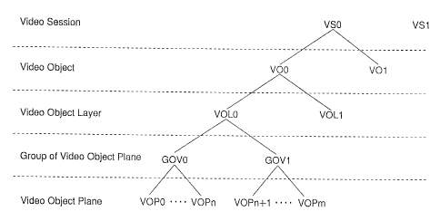
1 and 2 are based on MPEG-1/2 standard. Currently a system
for encoding video at a unit of the video object (VO) of an
object sequence constituting an image is being standardized
as MPEG-4 standard by the ISO-IEC/JTC1/SC29/WG11.
Incidentally, since the MPEG-4 standard is being
standardized on the assumption.that it is primarily used in
the field of communication, it does nat prescribe the group
of pictures (GOP) prescribed in the MPEG-1/2 standard.
Therefore, in the case where the MPEG-4 standard is utilized
in storage media, efficient random access will be difficult.
11
CA 02421090 2004-07-28
Disclosure of Invention
The present invention has been made in view of such
circumstances and therefore the object of the invention is
to make efficient; random access possible.
According to a first aspect of the invention, an image encoder is
characterized i~n that it comprises encoding means for
partitioning one or more layers of.~each~sequence of objects
constituting an image into a plurality of~groups and
encoding the. groups.
According to a second aspect of the invention, an image encoding
method is characterized in that it comprises an encoding step of
partitioning one ;or more layers of each sequence of objects
constituting an image into a plurality of groups and
encoding the groups.
According to a third aspect of the invention, an image encoder is
characterized in that it~comprises~ decoding means for
decoding a coded bit stream obtained by partitioning one or
more layers of each sequence.of objects~constituting an
image into a~plurality of groups and~also.by encoding the
groups . ~ , .
According to a fourth aspect of the~invention, an image decoding
method is characterized in that it comprises an .decoding step of
decoding a coded bit stream obtained~by partitioning one or
more layers of each sequ~erice of objects constituting an
12
CA 02421090 2004-07-28
image into a plurality of groups and also by encoding the.
groups.
According to a fifth aspect of the invention, a distribution medium
is characterized in that it distributes the coded bit stream
which is obtained. by partitioning one or more layers of each
sequence of objects constituting an image into a plurality
of groups and encoding the groups.
According to a sixth aspect of the invention', an image encoding
method is characterized,in that it comprises: second-accuracy time
information generation means for generating second-accuracy
time information which indicates time within accuracy of a
second; and detailed time information generation means for
generating. detailed time information which indicates a time
. . . r
geriod~betv~ieen the second-accuracy ti-me information directly
before displax time of the I-YOP., P=VOP, or B-VOP and the
display time within accuracy Finer than accuracy of a second.
According to a seventh aspect of the invention, an image decoding
method is characterized in that it comprises: a second-accuracy time
information generation step of generating second-accuracy
time information which indicates time within accuracy of a '
second; and a:detailed time information generation step of
generating detailed time information which~in~dicates a time
period between.the,.second-accuracy time information~directly
before disphay time of the, I-VOP, P-Vt~P, or ~B-VOP and the
display time within accuracy finer than,accuracy.of a.second.
13
CA 02421090 2004-07-28
An image decoder according to the eighth,aspect of the invention, is
characterized in that it comprises display time computation
means for computing display time of I-VOP, P-YOP, or B-YOP
on the basis of the second-accuracy,time informat~.on and
detailed time information.
An image decoding method according to the ninth aspect of the
invention, is characterized in that is comprises a display.time
computation,step of computing display time of.I-yOP, P-VOP,
or H-VOP on the basis of the second-accuracy time
information and detailed time information.
A distribution medium according to the tenth aspect of the
invention, is characterized in that it distributes a coded bit stream
which is obtained by generat~,ng second-accuracy time
info~ma.tion Which indicates time within accuracy of ~a second,
also by generating detailed time information which indicates
a time period between the second-accuracy time.information
. directly before display time of the~~I-VOP., P-YOP,.or B-YOP
and: the display .time within accuracy finer than accuracy. of
a second,, and furthermore ~y adding the'second-accuracy, time
information~and detailed'. time information to a corresponding
. .. . ~ ,
I-YOP, P-YOP, or B=VOP as information~which'indicates.
display t~.me of .the I-YOP, P-VOP, or B-VOP.
In the image encoder~according to first aspect of the invention, the
encoding ~ means part~.tions~ one or, more layers of each of
'objects. constituting an image into' a plurality of groups: and
14
CA 02421090 2004-07-28
encodes the groups:
In the image encoding method according to the~second aspect of the
invention, one or more layers of each sequence of objects constituting
an image is partitioned into a'glurality of groups, and the
groups are encoded.
In the image encoder according to the third aspect of the invention,
the decoding means decoded a coded bit stream obtained by
partitioning one or more layers of each sequence of objects
donstituti.ng an image into a plurality~of groups and also by.
In the image decoding method according to the fouxth aspect of the
invention, a coded bit stream obtained by. partitioning one or more
a coded~bit stream, obtained by.partitioning one or:more
layeirs of~ ~ each of objects constituting an image into a
plurality of groups and also by encoding the groups~is
decoded.
In the distribution medium according.to the fifth aspect of the
invention, a.coded bit stream, which is~obtained by partitioning one or
more'layers.of each sequence of objects constituting an'
image into a plurality of groups and~en~coding the groups is
distributed.
In the image encoder according to the-sixth aspect o~f the invention,
the second-accuracy time information generation means generates
second-accuracy time information which indicates time within.
accuracy of a second, and the detailed. time information
generation.means generates detailed time information which
CA 02421090 2004-07-28
indicates a time period between the second-accuracy time
information directly before display time of the I-VOP, P-VOP,
or B-VOP and tha display time within accuracy finer than
accuracy of a .second. ~ y
In the image encoding method according to the seventh aspect of the
invention second-accuracy time information which indicates time within
accuracy of a,second is generated, and detailed time
information,~which indicates a time period between the
second-accuracy time iaformation~directly before display'
time of the'I-VOP, P-VOP, or B-VOP and the display time
within acauracy.finer than accuracy of a second is generated.
In the image-decoder according to thewighth aspect. of the invention,
the display time computation means computes display time of .I-
VOP, P-VOP,~or~B-VOP on the basis of the second=accuracy
tame''information and detailed time information. ~ .
In the image decoding method according to~the ninth aspect of the
invention, display.time of I-VOP, P-VOP, or B-VOP is computed on the
basis of the second-accuracy time information andrdetailed.
time information,.
In the distribution medium according to the'tenth aspect of the
invention, the medium distributes a coded~bit stream which~is obtained
by generating second-accuracy~time information'which
indicates . time within accuracy ~of a second, . 'also ~by
generating detailed time information~whic_h indicates a time
period between the second-accuracy time in~ormation.directly
16
CA 02421090 2003-03-19
before display time of the I-VOP, P-VOP, or B-vOP and the
display time within accuracy finer than accuracy of a second,
and furthermore by adding the second--accuracy time
information and detailed time information to a corresponding
I-VOP, P-VOP, or B-VOP as information which indicates
display time of the I-VOP, P-VOP, or B-VOP.
Brief Description of the Drawings
Figure 1 is a block diagram showing the constitution
example of a conventional encoder;
Figure 2 is a block diagram showing the constitution
example of a conventional decoder;
Figure 3 is a block diagram showing the constitution
example of an embodiment of an encoder to which the present
invention is applied;
Figure 4 is a diagram for explaining that the position
and size of a video object (VOj vary with time;
Figure 5 is a block diagram showing the constitution
example of the VOP encoding sections ~l to 3N of Figure
Figure 6 is a diagram for explaining spatial
scalability;
Figure 7 is a diagram for explaining spatial
scalability;
Figure 8 is a diagram for explaining spatial
scalability;
17
CA 02421090 2003-03-19
Figure 9 is a diagram for explaining spatial
scalability;
Figure 10 is a diagram for explaining a method of
determining the size data and offset data of a video object
plane (YOP) ;
Figure 11 is a block diagram showing the constitution
example of the base layer encoding section 25 of Figure 5;
Figure 12 is a block diagram showing the constitution
example of the enhancement layer encoding section 23 of
Figure 5;
Figure 13 is a diagram for explaining spatial
scalability;
Figure 14 is a diagram for explaining time scalability;
Figure 15 is a block diagram showing the constitution
example of an embodiment of a decoder to which the present
invention is applied;
Figure 16 is a block diagram showing another
constitution example of the VOP decoding sections 721 to 72~
of Figure 15;
Figure 17 is a block diagram showing the constitution
example of the base layer decoding section 95 of Figure 16;
Figure 18 is a block diagram showing the constitution
example of the enhancement layer decoding section 93 of
Figure 16;
Figure 19 is a diagram showing the syntax of a bit
18
CA 02421090 2003-03-19
stream obtained by scalable coding;
Figure 20 is a diagram showing the syntax of VS;
Figure 21 is a diagram showing the syntax of a VO;
Figure 22 is a diagram showing the syntax of a VOL;
Figure 23 is a diagram showing the syntax of a VOP;
Figure 24 is a diagram showing the relation between
modulo time base and VOP time increment;
Figure 25 is a diagram showing the syntax of a bit
stream according to the present invention;
Figure 26 is a diagram showing 'the syntax of a GOV;
Figure 27 is a diagram showing the Constitution of
time code;
Figure 28 is a diagram showing a method of encoding the
time code of the GOV Layer and the modulo time base and
VOP time increment of the first I-VOP of the GOV;
Figure 29 is a diagram showing a method of encoding the
time_code of the GOV layer and also the moduloytime~base and
VOP time increment of the B-VOP located before the first I-
VOP of the GOV;
Figure 30 is a diagram showing t:he relation between the
modulo time base and the VOP time increment when the
definitions thereof are not changed;
Figure 31 is a diagram showing a process of encoding
the modulo time base and VOP time increment of the B-VOP,
based on a first method;
19
CA 02421090 2003-03-19
Figure 32 is a flowchart showing a process of encoding
the modulo_timerbase and VOP-timerincrement of I/P-VOP,
based on a first method and a second method;
Figure 33 is a flowchart showing a process of encoding
the modulo-time base and VOP_time_inc:rement of the B-VOP,
based on a first method;
Figure 34 is a flowchart showing a process of decoding
the modulo time base and VOP time increment of the I/P-VOP
encoded by the first and second methods;
Figure 35 is a flowchart showing a process of decoding
the modulo time base and VOP time increment of the B-VOP
encoded by the first method;
Figure 36 is a diagram showing a process of encoding
the modulo time base and VOP time increment of the B-VOP,
based on a second method;
Figure 37 is a flowchart showing the process of
encoding the modulo-time~base and VOF~_time_increment of the
B-VOP, based on the second method;
Figure 38 is a flowchart showing a pracess of decoding
the modulo time base and VOP time increment of the B-VOP
encoded by the second method;
Figure 39 is a diagram for explaining the
modulo time base; and
Figure 40 is a block diagram showing the constitution
example of another embodiment of an encoder and a decoder to
CA 02421090 2004-07-28
which the present invention is applied.
Best Mode for Carrying Out the Invention
Embodiments of the-present invention will hereinafter
be described in detail with reference to the drawings.
Before that, in order to make clear~the corresponding'.
relation between each means of the, present invention as se,t
forth in claims and the~following embodiments, the
characteristics of the present invention will hereinafter be
.described in detail by adding a corresponding embodiment
within a parenthesis after each means. The corresponding.
embodiment i s merely an ~ e~campl a .
That is., the image encoder according to the first aspect of the
invention, characterized in that it is an image encoder for encoding an
image and outputting.the resultant coded~bit stream, the
imagevencoder comprising: receivin.g.means for receiving the
image (e . g . , , frame memory ; 31 shown i.n Figure 11 or 12 ,
etc. )~ : and' encoding means for partitioning one or. more
layers of each of objects constituting the image into a
plurality. of groups and encoding the grc5ups~(e.g.,.VhC unit
36 shown in~ Figure 11 ~or. 12, etc: ) .
Further, the image encoder according to the first aspect of the
invention, is characterized in that, when it is assumed that an object
which is encoded by intracoding is an~i.ntra=video object
plane 1(I-VOP), an..object which is encoded by either
21
CA 02421090 2004-07-28
intracoding or forward predictive Coding is a predictive-VOP
(P-VOP), and that an object which is encoded byveither
intracoding, forward predictive coding, backward predictive
coding, or bidirectionally predictive coding.is a
bidirectionally-predictive-VOP (B-VOP), the image encoder
further compris-es: second-accuracy time information
generation means for generating second-accuracy time
information~which indicates time within accuracy of a second
based on encoding start second-accuracy absolute~time.(e.g.;
processing steps S3 to S? in the-program shown in Figure 32,
processing steps S43 to S4? in the program shown in Figure
3?,. etc.): detailed time information generation means-for
generating-detailed time information Which indicates a time
peripd between the second-accuracy time. information directly
before~display time of the I-YOP,.vP-VOP, or-B-YOP.included
_,
in the object. group-and the display time within accuracy
finer than accuracy of a second-(e.g., processing step S8 in
the program shown-in F~.gure 32, processing step S48 in the
program shown in Figure 3?, etc.); and addition m~ans.for~
adding the. second-accuracy time information and detailed
time information to -a corrsspond~.ng I-YOP, P-YOP, . or. -B-YOP .
as iwformation which indicates-display time of the I-VOP,-.P-
VOP, -or B-YOP ~ (e.g.. , YLC uni-t 36 shown in Figure 11 or 12,
etc . ) .
The image decoder according to the third.aspect-of the invention, is
22
CA 02421090 2004-07-28
characterized in that it is an image decoder for~decoding an
image, the.image decoder comprising: receiving means for
rece~.ving a coded bit stream obtained by partitioning one. or
more layers of each of objects constituting the image into a
plurality of groups and also by encoding the groups (e. g.,
buffer 101 shown in Figure 17 or 18; etc.)-; and decoding
means for decoding the coded bit stream (e.g:., IVLC unit 102
shown in Figure 17 or 18, etc.).
Further, the image decoder according to the third aspect of the
invention, is characterized in~that a group of objects includes encoding
stmt second-accuracy absolute time which is. absolute time
on an image sequence that started the encoding and also
which is time within accuracy.of a second and i~n that the
image decoder further comprises display time computation
means ~. for computing the 'display time of 'an object included
in the group of objects on this basis of the encoding start
second-accuracy absolute time (e.g., proces.sing steps S22 to
S27 in the program shown in Figure_34,~processing steps~S52
to S57 in the. programshown in .Figure 3'8, etc. j-
The image encoder according to the sixth aspect of the invention, is
characterized ~ in that, in an image encoder for encoding: an .
image for each o~f objects constituting the image and
outputting.the resultant coded bit ,stream, When it is'
assumed~that an object wyich is encoded,by intracoding is an~
i.ntra-video object plane -(I-YOP) , an object whicH _~sv encoded
23
CA 02421090 2004-07-28
b~ either intracoding,or'forward predictive coding'is a
. predictive-VOP ,(P-VOP) , and that an' ~obj ect. which' ~is encoded
by . either intracoding-, forward predictive' coding, ~ backward
predictive coding,'or bidirectionally predictive-coding is a
bidirectionally predictive-VOP (B-VOP).-, the image encoder
comprises: second-accuracy time. information generation.
-means for generating-second-accuracy time information~Which
indicates time withiw accuracy ofva second (e.g.r processing
' steps S3 to S7.in the. program shown~in~Figure 32, processing
steps .S43 to rS47 in the program . shown. in Figure 37, etc. ) ;
detailed time. information generation, means for..generat,ihg
detailed time~information which indicates a~time period
betty~eri the seaond~accnracy~ time information directly before
display time of the I-VOP, p-VOP~, _ or B-VOP ~~and the display
~ti~ne. .Within accuracy finer than ~ accuracy of a' second (e', g . ,
proces_sing~step SS invthe program shown in Figure 32,
processing step S4~ in _the~ -program shown in Figure 37~,
. - ' ' . ', . . ,. . . . , .,
etc'. ) ; and addition~.~means for adding the. second-accuracy ~,
tiine~ iriforfiation-,anii -detailed time information ~to a
corresponding I-VOP.r _P-VOP, or B-VOP as. informati~Qn,which '
indicates, the'' display time of the,1I-VOP, P-VOP; Gird ;B'-VOP
(e:g.. , VLC 'unit .36 - shown, in Figure 11 : or~- 12, etc~. ) ,..
The image.decoder according to the e.iqhth aspect of the invention, i5
' characterized in that, i.n.an image decoder.for decoding a '
,coded bi.t~ stream obtained by, encoding.' an image ~ for each of
. 24.
CA 02421090 2003-03-19
objects constituting the image, when it is assumed that an
object which is encoded by intracoding is an intra-video
object plane (I-VOP), an object which is encoded by either
intracoding or forward predictive coding is a~predictive-VOP
(P-VOP), and that an object which is encoded by either
intracoding, forward predictive codir.:g, backward predictive
coding, or bidirectionally predictive: coding is a
bidirectionally predictive-VOP (B-VO~') and when both second-
accuracy time information indicating time within accuracy of
a second and detailed time information indicating a time
period between the second-accuracy time information directly
before display time of the I-VOP, P-VOP, or B-VOP and the
display time within accuracy finer than accuracy of a second
have been added to a corresponding I-VOP, P-VOP, or B-VOP as
information which indicates the display time, the image
decoder comprises: display time computation means for
computing the display time of the I-VOP, P-VOP, or B-VOP on
the basis of the second-accuracy time information and
detailed time information (e.g., processing steps S22 to S27
in the program shown in Figure 34, processing steps S52 to
S57 in the program shown in Figure 38, etc.); and decoding
means for decoding the I-VOP, P-VOP, or B-VOP in accordance
with the corresponding display time (sa.g., IVLC unit 102
shown in Figure 17 or 18, etc.).
Note that, of course, this description does not mean
CA 02421090 2003-03-19
that each means is limited to the aforementioned.
Figure 3 shows the constitution example of an .
embodiment of an encoder to which the present invention is
applied.
Image (dynamic image) data to be encoded is input to a
video object (VO) constitution section 1, rn the VO
constitution section 1, the image is constituted for each
object by a sequence of VOs. The sequence of VOs are output
to VOP constitution sections 21 to 2N. That is, in the VO
constitution section 1, in the case where N video objects
4V0#1 to VO#N) are produced, the VO#~. to VO#N are output to
the VOP constitution sections 21 to 2N, respectively.
More specifically, for example, when image data to be
encoded is constituted by a sequence of independent
background F1 and foreground F2, the VO constitution section
1 outputs the foreground F2, for example, to the VOP
constitution section 21 as VO#1 and also outputs the
background F1 to the VOP constitution section 22 as VO#2.
Note that, in the case where image data to be encoded
is, for example, an image previously synthesised by
background F1 and foreground F2, the VO constitution section
1 partitions the image into the background F1 and foreground
F2 in accordance with a predetermined algorithm. The
background F1 and foreground F2 are output to corresponding
VOP constitution sections 2n where n = 1, 2, ..., and N).
26
CA 02421090 2003-03-19
The VOP constitution sections 2n produce VO planes
(VOPs) from the outputs of the VO constitution section 1.
That is, for example, an object is extracted from each frame.
For example, the minimum rectangle surrounding the object
(hereinafter referred to as the minimum rectangle as needed)
is taken to be the VOP. Note that, at this time, the VOP
constitution sections 2n produce the VOP so that the number
of horizontal pixels and the number of vertical pixels are a
multiple of 16. If the VO constitution sections 2n produce
VOPs, the VOPs are output to VOP encoding sections 3n,
respectively.
Furthermore, the VOP constitution sections 2n detect
size data (VOP size) indicating the size of a VOP (e. g.,
horizontal and vertical lengths) and offset data (VOP
offset) indicating the position of th.e VOP in a frame (e. g.,
coordinates as the lef t uppermost of a frame is the origin).
The size data and offset data are also supplied to the VOP
encoding sections 3n.
The VOP encoding sections 3n encode the outputs of the
VOP constitution sections 2n, for example, by a method based
on MPEG standard or H.263 standard. The resulting bit
streams are output to a multiplexing section 4 which
multiplexes the bit streams obtained from the VOP encoding
sections 31 to 3N. The resulting multiplexed data is
transmitted through a ground wave or through a transmission
27
CA 02421090 2003-03-19
path 5 such as a satellite line, a CATV network, etc.
Alternatively, the multiplexed data is recorded on storage
media 6 such as a magnetic disk, a magneto-optical disk, an
optical disk, magnetic tape, etc.,
Here, a description will be made of the video object
(VO) and the video object plane (VOP) .
In the case of a synthesized image, each of the images
constituting the synthesized image is. referred to as the VO,
while the VOP means a VO at a certain time. That is, for
example, in the case of a synthesized image F3 constituted
by images F1 and F2, when the image F1 and F2 axe arranged
in a time series manner, they are VOs. The image F1 or F2
at a certain time is a VOP. Therefore, it may be said that
the VO is a set of the VOPs os the same object at different
times .
For instance, if it is assumed that image F1 is
background and also image F2 a~s foreground, synthesized
image F3 will be obtained by synthesizing the images F1 and
F2 with a key signal for extracting the image F2. The VOP
of the image F2 in this case is assumed to include the key
signal in addition to image data luminance signal and color
difference signal) constituting the image F2.
An image frame does not vary in both size and position,
but there are cases where the size or position of a VO
changes. That is, even in the case a VOP constitutes the
~8
CA 02421090 2003-03-19
same VO, there are cases where the size or position varies
with time.
Specifically, Figure 4 illustrates a synthesized image
constituted by image F1 (background) and image F2
(foreground) .
For example, assume that the image F1 is an image
obtained by photographing a certain natural scene and that
the entire image is a single VO (e. g., VO#0). Also assume
that the image F2 is an image obtained by photographing a
person who is walling and that the minimum rectangular
surrounding the person is a single VO (e. g., VO#1).
In this case, since the VO#O is the image of a scene,
basically both the position and the size do not change as in
a normal image frame. On the other haand, since the VO#1 is
the image of a person, the position o.r the size will change
if the person moves right and left or moves toward this side
or depth side in Fir~ure 4. therefore, although Figure 4
shows VO#0 and VO#1 at the same time, there are cases where
the position or size of the VO varies with time.
Hence, the output bit stream of the VOP encoding
sections 3n of Figure 3 includes info:rmati.on on the position
(coordinates) and size of a VOP on a predetermined absolute
coordinate system in addition to data indicating a coded VOP.
Dlote in Figure 4 that a vector indicating the position of
the VOP of VO#0 (image F1) at a certain time is represented
29
CA 02421090 2003-03-19
by OSTO and also a vector indicating the position of the VOP
of VO#1 (image F2) at the certain time is represented by
OST1. .
Next, Figure 5 shows the constitution example of the
VOP encoding sections 3n of Figure 3 which realize
scalability. That is, the MPEG standard .introduces a
scalable encoding method which reali2:es scalability coping
with different image sizes and frame rates. The VOP
encoding sections 3n shown in Figure 5 are constructed so
that such scalability can be realizeci.
The VOP (image data) , the size' data (VOP size) , and
offset data (VOP offset) from the VOP constitution sections
2n are all supplied to an image layering section 2I.
The image layering section 21 ga~nerates one or more
layers of image data from the VOP (layering of the VOP is
performed). That is, for example, in the case of performing
encoding of spatial scalability, the image data input to the
image layering section 2I, as it is, is output as an
enhancement layer of image data. At the same time, the
number of pixels constituting the image data is reduced
(resolution is reduced) by thinning out the pixels, and the
image data reduced in number of pixels is output as a base
layer of image data.
Note that an input VOP can be employed as a base layer
of data and also the VOP increased ire pixel number
CA 02421090 2003-03-19
(resolution) by some other methods can be employed as an
enhancement layer of data.
In addition, although the number of layers can be made
1, this case cannot realize scalability. In this case, the
VOP encoding sections 3n are constituted, for example, by a
base layer encoding section 25 alone.
Furthermore, the number of layers can be made 3 or more.
But in this embodiment, the case of two layers will be
described for simplicity.
For example, in the case of per:~orming encoding of
temporal scalability, the image layering section 21 outputs
image data, for example, alternately base layer data or
enhancement layer data in correspondence to time. That is,
for example, when it is assumed that the VOPs constituting a
certain VO are input in order of VOPO, VOP1, VOP2, VOP3, ...,
the image layering section 21 outputs VOPO, VOP2, VOP4,
VOP6, ... as base layer data and VOP1, VOP3, VOP5, VOF7, ..,
as enhancement layer data. Note that, in the case of
temporal scalability, the VOPs thus thinned out are merely
output as base layer data and enhancement layer data and the
enlargement or reduction of image data (resolution
conversion] is not performed (But it is possible to perform
the enlargement or reduction).
Also, for example, in the case of performing the
encoding of signal-to-noise ratio (SNR) scalability, the
~1
CA 02421090 2003-03-19
image data input to the image layering section 21, as it is,
is output as enhancement layer data or base layer data.
That is, in this case, the base layer data and the
enhancement layer data are consistent with each other.
Here, for the spatial scalabilit~y in the case of
performing an encoding operation for each VOP, there are,
for example, the following three kinds.
That is, for example, if it is n ow assumed that a
synthesized image consisting of images F1 and F2 such as the
one shown in Figure 4 is input as a VOP, in the first
spatial scalability the input entire VOP (Figure 6'(A)) is
taken to be an enhancement layer, as shown in Figure 6, and
the entire VOP reduced (Figure ~(B)) is taken to be a base
layer.
Also, in the second spatial scal.ability, as shown in
Figure 7, an object constituting part of an input VOP
(Figure 7(A) (which corresponds to image F2)) is extracted.
The extracted object is taken to be an enhancement layer,
while the reduced entire VOP (Figure 7(~)~ is taken to be a
base layer. (Such extraction is performed, for example, in
the same manner as the case of the VOP constitution sections
2n. Therefore, the extracted object ~_s also a single VOP.)
Furthermore, in the third scalability, as shown in
Figures 8 and 9, objects (VOP) constituting an input VOP are
extracted, and an enhancement layer and a base layer are
S2
CA 02421090 2003-03-19
generated for each object. Note that Figure 8 shows an
enhancement layer and a base layer generated from the
background (image F1) constituting the VOP shown in Figure 4,
while Figure 9 shows an enhancement layer and a base layer
generated from the foreground (image F2) constituting the
VOP shown in Figure 4.
It has been predetermined which of the aforementioned
scalabilities is employed. The image layering section 21
performs layering of a VOP so that encoding can be performed
according to a predetermined scalability.
Furthermore, the image layering section 21 computes (or
determines) the size data and offset data of generated base
and enhancement layers from the size data and offset data of
an input VOP (hereinafter respectively referred to as
initial size data and initial offset data as needed). The
offset data indicates the position of a base or enhancement
layer in a predetermined absolute coordinate system of the
VOP, while the size data indicates the size of the base or
enhancement layer.
Here, a method of determining the offset data (position
information) and size data of VOPs in base and enhancement
layers will be described, for example, in the case where the
above-mentioned second scalability (Figure 7) is performed.
In this case, for example, the offset data of a base
layer, FPOS H, as shown in Figure 10(.A), is determined so
33
CA 02421090 2003-03-19
that, when the image data in the base: layer is enlarged
(upsampled) based on the difference between the resolution
of the base layer and the resolution of the enhancement
layer, i.e., when the image in the base layer is enlarged
with a magnification ratio such that the size is consistent
with that of the image in the enhancement layer (a
reciprocal of the demagnification ratio as the image in the
base layer is generated by reducing the ianage in the
enhancement layer) $hereinafter referred to as magnification
FR as needed), the offset data of the enlarged image in the
absolute coordinate system is consistent with the initial
offset data. The size data of the base layer, FSZ B, is
likewise determined so that the size data of an enlarged
image, obtained when the image in the base layer is enlarged
with magnification FR, is consistent with the initial size
data. That is, the offset data FPOS 1~ is determined so that
it is FR times itself or consistent with the initial offset
data. Also, the size data FSZPB is determined in the same
manner.
On the other hand, for the offset data EPOS E of an
enhancement layer, the coordinates of the lef t upper corner
of the minimum rectangle $VOP) surrounding an object
extracted from an input VOP, for example, are computed based
on the initial offset data, as shown in Figure 10(B), and
this value is determined as offset data FPOS E. Also, the
34
CA 02421090 2003-03-19
size data FPOS E of the enhancement layer is determined to
the horizontal and vertical lengths, for example, of the
minimum rectangle surrounding an object extracted from an
input VOP.
Therefore, in this case, the offset data FPOS B and
size data FPOS B of the base layer are first transformed
according to magnification FR. (The offset data FPOS ~ and
size data FPOS B after transformation are referred to as
transformed offset data FPOS B and transformed size data
FPOS B, respectively.) Then, at a position corresponding to
the transformed offset data FPOS B in the absolute
coordinate system, consider an image frame of the size
corresponding to the transformed size data FSZ B. If an
enlarged image obtained by enlarging the image data in, the
base layer by FR times is arranged at the aforementioned
corresponding position {Figure lfl{A)) and also if the image
in the enhancement layer is likewise arranged in the
absolute coordinate system in accordance with the offset
data FPOS E and size data FPOS E of the enhancement layer
(Figure 10(B)), the pixels constituting the enlarged image
and the pixels constituting the image in the enhancement
layer will be arranged so that mutually corresponding pixels
are located at the same position. That is, for example, in
Figure 10, the person in the enhancement layer and the
person in the enlarged image wi-11 be .arranged at the same
CA 02421090 2003-03-19
positron.
Even in the case of the first scalability and the third
scalability, the offset data FPOS B, offset data FPOS E,
size data FSZ B, and size data FSZ E are likewise determined
so that mutually corresponding pixels constituting an
enlarged image in a base layer and an. image in an
enhancement layer are located at the same position in the
absolute coordinate system.
Returning to Figure 5, the image data, offset data
FPOS E, and size data FSZ E in the enhancement layer,
generated in the image layering section 21, are delayed by a
delay circuit 22 by the processing period of a base layer
encoding section 25 to be described later and are supplied
to an enhancement layer encoding section 23. Also, the
image data, offset data FPOS~B, and size data FSZ B in the
base layer are supplied to the base,layer encoding section
25. In addition, magnification FR is supplied to the
enhancement layer encoding section 23 and resolution
transforming section 24 through the delay circuit 22.
In the base layer encoding section 25, the image data
in the base layer is encoded. The resultant coded data (bit
stream) includes the offset data FPOS B and size data FSZ B
and is supplied to a multiplexing section 26.
Also, the base layer encoding section 25 decodes the
coded data locally and outputs the locally decoded image
36
CA 02421090 2003-03-19
data in the base layer to the resolution transforming
section 24. In the resolution transforming section 24, the
image data in the base layer from the base layer encoding
section 25 is returned to the original size by enlarging (or
reducing) the image data in accordance with magnification FR.
The resultant enlarged image is output to the enhancement
layer encoding section 23.
On the other hand, in the enhancement layer encoding
section 23, the image data in the enhancement layer is
encoded. The resultant coded data (b:it stream) includes the
offset data FPOS E and size data FSZ E and is supplied to
the multiplexing section 26. Note th<~t in the enhancement
layer encoding section 23, the encoding of the enhancement
layer image data is performed by employing as a reference
image the enlarged image supplied from the resolution
transforming section 24.
The multiplexing section 26 multiplexes the outputs~of
the enhancement layer encoding section 23 and base layer
encoding section 25 and outputs the multiplexed bit stream.
Note that the size data FSZ B, offset data FPOS B,
motion vector (MV), flag OOD, etc. of the base layer are
supplied from the base layer encoding section 25 to the
enhancement layer encoding section 23 and that the
enhancement layer encoding section 23 is constructed so that
it performs processing, making reference to the supplied
37
CA 02421090 2003-03-19
data as needed. The details will be described later.
Next, Figure 11 shows the detailed constitution example
of the base layer encoding section 25 of Figure 5. In
Figure 11, the same reference numerals are applied to parts
corresponding to Figure 1. That is, basically the base
layer encoding section 25 is constituted as in the encoder
of Figure 1.
The image data from the image layering section 21
(Figure 5), i.e., the VOP in the base layer, as with Figure
1, is supplied to a frame memory 31 and stored. In a motion
vector detector 32, the motion vector is detected at a
macroblock unit.
But the size data FSZ B and offset data FPOS B of the
VOP of a base layer are supplied to the motion vector
detector 32 of the base layer encoding section 25, which in
turn detects the motion vector of a macroblock, based on the
supplied size data FSZ B and offset data FPOS B.
That is, as described above, the size and position of a
VOP vary with time (frame3. Therefore, in detecting the
motion vector, there is a need to set a reference coordinate
system for the detection and detect motion in the coordinate
system. Hence, in the motion vector detector 32 here, the
above-mentioned absolute coordinate s~~stem is employed as a
reference coordinate system, and a VOl? to be encoded and a
reference VOP are arranged in the absolute coordinate system
38
CA 02421090 2003-03-19
in accordance with the size data FSZ B and offset data
EPOS B, whereby the motion vector is detected.
Note that the detected motion vEactor (MV), along with
the predictive mode, is supplied to a. VLC unit 36 and a
motion compensator ~2 and is else supplied to the
enhancement layer encoding section 23 (Figure 5).
Even in the case of performing motion compensation,
there is also a need to detect motion in a reference
coordinate system, as described above. Therefore, size data
FSZ B and offset data FPOS B are supplied to' the motion
compensator 42.
A VOP whose motion vector was detected is quantized as
in the case of Figure 1, and the quantized coefficients are
supplied to the VLC unit 36. Alsa, a>s in the case of Figure
1, the size data FSZ B and affset data FPOS B from the image
layering section 21 are supplied to the VLC unit 36W n
addition to the quantized coefficients, quantization step,
motion vector, and predictive mode. In the VLC unit 36, the
supplied data is encoded by variable word length coding.
In addition to the above-mentioned encoding, the VOP
whose motion vector was detected is locally decoded as in
the case of Figure 3 and stored in frame memory 41. This
decoded image is employed as a reference image, as
previously described, and furthermore, it is output to the
resolution transforming section 24 (Figure 5).
39
CA 02421090 2003-03-19
Note that, unlike the MPEG-1 standard and the MPEG-2
standard, in the MPEG-4 standard a B-picture (B-VOP) is also
employed as a reference image. For this reason, a B-picture
is also decoded iocaliy and stored in the frame memory 41.
(However, a B-picture is presently employed only in an
enhancement layer as a reference image.)
On the other hand, as described in Figure 1, the VLC
unit 36 determines whether the macroblock in an I-picture, a
P-picture, or a B-picture $I-VOP, P-V~OP, or B-VOP) is made a
skip macroblock. The VLC unit 36 sets flags COD and MODB
indicating the determination result. The flags COD and MODB
are also encoded by variable word length coding and are
transmitted. Furthermore, the flag CUD is supplied to the
enhancement layer encoding section 23.
Next, Figure 12 shows the constitution example of the
enhancement layer encoding section 23 of figure 5. In
Figure I2, the same reference numerals are applied to parts
corresponding to Figure 11 or 1. That: is, basically the
enhancement layer encoding section 23 is constituted as in
the base layer encoding section 25 of Figure 11 or the
encoder of Figure 1 except that frame memory 52 is newly
provided.
The image data from the image layering section 21
(Figure 5), i.e., the VOP of the enhancement layer, as in
the case of Figure 1, is supplied to t:he frame memory 31 and
CA 02421090 2003-03-19
stored. In the motion vector detector 32, the motion vector
is detected at a macroblock unit. Even in this case, as in
the case of Figure 11, the size data FSZ_E and offset data
FPOS E are supplied to the motion vector detector 32~in
addition to the VOP of the enhancement layer, etc. In the
motion vector detector 32, as in the above-mentioned case,
the arranged position of the VOP of the enhancement layer in
the absolute coordinate system is recognized based on the
size data FSZ E and offset data FPOS E, and the motion
vector of the macrobloc~ is detected.
Here, in the motion vector detectors 32, of the
enhancement layer encoding section 23 and base layer
encoding section 2~, VOPs are processed according to a
predetermined sequence, as described in Figure 1. For
example, the sequence is set as follows.
That is, in the case of spatial scalability, as shown
in Figure 13(A) or 13(B), the VOPs in an enhancement layer
or a base layer are processed, for example, in order of P, B,
B, B, ... Or I, P, P, P, ...
And in this case, the first P-picture (P-VOP) in the.
enhancement layer is encoded, for example, by employing as a
reference image the VOP of the base laayer present at the
same time as the P-picture (here, I-picture (I-VOP)). Also,
the second B-picture (B-VOP) in the enhancement layer is
encoded, for example, by employing as reference images the
41
CA 02421090 2003-03-19
picture in the enhancement layer immediately before that and
also the VOP in the base layer present at the same time as
the B-picture. That is, in this example, the B-picture in
the enhancement layer, as with th.e P--picture in base layer,
is employed as a reference image in Encoding another VOP.
For the base layer, encoding is performed, for example,
as in the case of the MPEG-1 standard, MPEG-2 standard, or H.
263 standard.
The SNR scalability is processed in the same manner as
the above-mentioned spatial scalabili.ty, because it is the
same as the spatial scalability when the magnification FR in
the spatial scalability is 1.
In the case of the temporal scalability, i.e., for
example, in the case where a VO is constituted by VOPO, VOP1,
VOP2, VOP3, ..., and also VOP1, VOP3, VOP5, VOP7, .,. are
taken to be in an enhancement layer ;Figure 14(A)) and VOPO,
VOP2, VOP4, VOP6, ... to be in a base layer (Figure 14(B)),
as described above, the VOPs in the ~:nhancement and base
layers are respectively processed in order of B, B, B, ...
and in order of I, P, P, P, ..., as shown in Figure 14.
And in this case, the first VOP:L (B-picture) in the
enhancement layer is encoded, for example, by employing the
VOPO (I-picture) and VOP2 (P-picture) in the base layer as
reference images. The second VOP3 (B-picture) in the
enhancement layer is encoded, for example, by employing as
42
CA 02421090 2003-03-19
reference images the first coded VOP1 (B-picture) in the
enhancement layer immediately before that and the VOP4 (P-
picture) in the base layer present at the time (frame) next
to the VOP3. The third VOP5 (B-picture) in the enhancement
layer, as with the encoding of the VOP3, is encoded, for
example, by employing as reference images the second coded
VOP3 (B-picture) in the enhancement layer immediately before
that and the VOP6 (P-picture) in the base layer which is an
image present at the time (frame) next to the VOPS.
As described above, for VOPs in one layer (here,
enhancement layer), VOPs in another layer (scalable layer)
(here, base layer) can be employed as reference images for
encoding a P-picture and a B-pictures In the case where a
VOP in one layer is thus encoded by employing a VOP in
another layer as a reference image, i.e., like this
embodiment, in the case where a VOP in the base layer is
employed as a reference image in encoding a VOP in the
enhancement layer predictively, the motion vector detector
32 of the enhancement layer encoding section 23 (Figure 12)
is constructed so as to set and output flag ref-layerrid
indicating that a VOP in the base layer is employed to
encode a VOP in the enhancement layer predictively. (fin the
case of 3 or more layers, the flag ref layer id represents a
layer to which a VOP, employed as a reference image,
belongs.)
43
CA 02421090 2003-03-19
Furthermore, the motion vector detector 32 of the
enhancement layer encoding section 2~ is constructed so as
to set and output flag ref~select-code (reference image
information) in accordance with the flag .ref layer id for a
VOP. The flag ref~select_code (reference image information)
indicates which layer and which VOP in the layer are
employed as a reference image in performing forward
predictive coding or backward predictive coding.
More specifically, for example, in the case where a P-
picture in an enhancement layer is encoded by employing as a
reference image a VOP which belongs to the same layer as a
picture decoded (locally decoded) immediately before the P-
picture, the flag ref_select_code is set to 00. Also, in
the case where the P-picture is encoded by employing as a
reference image a VOP which belongs to a layer (here, base
layer (reference layer)) different from a picture displayed
immediately before the P-picture, the flag ref_select_code
is set to O1. In addition, in the case where the P-picture
is encoded by employing as a reference image a VOP which
belongs to a layer different from a picture to be displayed
immediately after the P-picture, the flag ref-select~code is
set to 10. Furthermore, in the case 'where the P-picture is
encoded by employing as a reference rage a VOP which
belongs to a different layer present at the same time as the
P-picture, the flag ref select code is set to li.
44
CA 02421090 2003-03-19
On the other hand, for example, in the case where a B-
picture in an enhancement layer is encoded by employing as a
reference image for forward prediction a VOP which belongs
to a different layer present at the ~~ame time as the B-
picture and also by employing as a reference image for
backward prediction a VOP which belongs to the sane layer as
a picture decoded immediately before the B-picture, the flag
ref select code is set to Ot~. Also, in the case where the
B-picture in the enhancement layer i~; encoded by employing
as a reference image for forward prediction a VOP which
belongs to the same layer as the B-picture and also by
employing as a reference image for backward prediction a VOP
which belongs to a layer different from a picture displayed
immediately before the B-picture, thE: flag ref select code
is set to O1. In addition, in the case where the B-picture
in the enhancement layer is encoded by employing as a
reference image for forward prediction a VOP which belongs
to the same layer as a picture decoded immediately before
the B-picture and also by employing a,s a reference image for
backward prediction a VOP which belongs to a layer different
from a picture to be displayed immediately after the B-
picture, the flag ref select code is set to 10. E°urthermore,
in the case where the B-picture in th.e enhancement layer is
encoded by employing as a reference image for forward
prediction a VOP which belongs to a layer different from a
4a
CA 02421090 2003-03-19
picture displayed immediately before the B-picture end also
by employing as a reference image fox backward prediction a
VOP which belongs to a layer different from a picture to be
displayed immediately after the B,-picture, the flag
ref select code is set to 11.
Here, the predictive coding shown in Figures I~ and 14
is merely a single example. Therefore, it is possible
within the above-mentioned range to suet freely which layer
and which VOP in the layer are employed as a reference image
for forward predictive coding, backward predictive coding,
or bidirectionally predictive coding.
In the above-mentioned case, while the terms spatial
scalability, temporal scalability, an;d BNR sc~lability have
been employed for the convenience of explanation, it becomes
difficult to discriminate the spatial scalability, temporal
scalability, and SNF scalability from each other in the case
where a reference image for predictive coding is set by the
flag ref select code. That is, conversely speaking, the
employment of the flag ref select code renders the above-
mentioned discrimination between scalabilites unnecessary.
Here, if the above-mentioned scalability and flag
ref select code are correlated with each other, the
correlation will be, for example, as follows. That is, with
respect to a P-picture, since the case of the flag
ref select code being 11 is a case where a VOP at the same
46
CA 02421090 2003-03-19
time in the layer indicated by the flag ref layer id is
employed as a reference image (for forward prediction), this
case corresponds to spatial scalability or SNR scalability.
And the cases other than the case of- the flag
ref_select_code being 11 correspond to temporal scalability.
Also, with respect to a P-picture, the case of the flag
ref select code being 00 is else the case where a VOP at the
same time in the layer indicated by the flag ref layer id is
employed as a reference image for forward prediction, so
this case corresponds to spatial scalability or SNR
scalability. And the cases other thaw the case of the flag
ref_select_code being 00 correspond to temporal scalability.
Note that, in the case where in order to encode a VIP
in an enhancement layer predictively, a VCP at the same time
in a layer (here, base layer) different from the enhancement
layer is employed as a reference image, there is no motion
therebetween, so the motion vector is always made 0 ((0,0)).
Returning to Figure 12, the afoz~ementioned.flag
ref-layer_id and flag refrselect_code are set to the motion
vector detector 32 of the enhancement layer encoding section
23 and supplied to the motion compensator 42 and PLC unit 36.
Also, the motion vector detector 32 detects a motion
vector by not making reference only to the frame memory 31
in accordance with the flag ref-layer_~id and flag
ref-select_code but else making reference to the frame
47
CA 02421090 2003-03-19
memory 52 as needed.
Here, a locally decoded enlarged image in the base
layer is supplied from the resolution transforming section
24 (Figure 5) to the frame memory 52. That is, in the
resolution transforming section 24, the locally decoded VOP
in the base layer is enlarged, for example, by a so-called
interpolation filter, etc. With this, an enlarged image
which is FR times the size of the VOP, i.e., an enlarged
image of the same size as the VOP in the enhancement layer
corresponding to the VOP in the base layer is generated.
The generated image is supplied to the enhancement layer
encoding section 23_ The frame memory 52 stores the
enlarged image supplied from the resolution transforming
section 24 in this manner.
Therefore, when magnification FR is 1, the resolution
transforming section 24 does not process the locally decoded
VOP supplied from the base layer encoding section 25. The
locally decoded VOP from the base layer encoding section 25,
as it is, is supplied to the enhancement layer encoding
section 23.
The size data FSZ B and offset data FPOS B are supplied
from the base layer encoding section 25 to the motion vector
detector 32, and the magnification FR from the. delay circuit
22 (Figure 5) is also supplied to the motion vector detector
32. In the case where the enlarged image stored in the
48
CA 02421090 2003-03-19
frame memory 52 is employed as a reference image, i.e., in
the case where in order to encode a V'OP in an enhancement
layer predictively, a VOP in a base layer at the same time
as the enhancement layer VOP is employed as a reference
image (in this case, the flag ref_select_code is made 11 for
a P-picture and 00 for a B-picture?, the motion vector
detector 32 multiplies the size data FSZ B and offset data
FPOS B corresponding to the enlarged image by magnification
FR. And based on the multiplication result, the motion
vector detector 32 recognizes the position of the enlarged
image in the absolute coordinate system, thereby detecting
the motion vector.
Note that the motion vector and predictive mode in a
base layer are supplied to the motion vector detector 32.
This data is used in the following case. That is, in the
case where the flag ref~select_code for a B-picture in an
enhancement layer is 00r when magnification FR is 1, i.e.,
in the case of SNR scalability (in this case, since a VOP in
an enhancement layer is employed in encoding the enhancement
layer predictively, the SNR scalability used herein differs
in this respect from that prescribed in the MPEG-2 standard),
images in the enhancement layer and base layer are the same.
Therefore, when the predictive coding of a B-picture in an
enhancement layer is performed, the motion vector detector
32 can employ the motion vector and predictive mode in a
49
CA 02421090 2003-03-19
base layer present at the same time a.s the H-picture, as
they are. Hence, in this case the motion vector detector 32
does not process the H-picture of the enhancement layer, but
it adopts the motion vector and predictive mode of the base
layer as they are.
In this case, in the enhancement layer encoding section
23, a motion vector and a predictive mode are not output
from the motion vector detector 32 to the VLC unit 36.
(Therefore, they are not transmitted.) This is because a
receiver side can recognize the motion vector and predictive
mode of an enhancement layer from the. result of the decoding
of a base layer.
As previously described, the moi~ion vector detector 32
detects a motion vector by employing both a VOP in an
enhancement layer and an enlarged image as reference images.
Furthermore, as shown in Figure l, th.e motion vecto r
detector 32 sets a predictive mode which makes a prediction
error (or dispersion) minimum. Also, the motion vector
detector 32 sets and outputs necessary information, such as
flag ref select code, flag ref layer id, etc.
In Figure 12, flag COD indicates whether a macroblock
constituting an I-picture or a P-picture in a base layer is
a skip macroblock, and the flag COD is supplied from the
base layer encoding section 25 to the motion vector detector
32, VLC unit 36, and motion compensator 42.
CA 02421090 2003-03-19
The macroblock whose motion vector was detected is
encoded in the same manner as the above-mentioned case. As
a result of the encoding, variable-length codes are output
from the VLC unit 36.
The VLC unit 36 of the enhancement layer encoding
section 23, as in the case of the base layer encoding
section 25, is constructed so as to set and output flags COD
and MODB. Here, the flag COD, as described above, indicates
whether a macroblock in an I- or P-p3.cture is a skip
macroblock, while the flag MODB indicates whether a
macroblock in a B-picture is a skip macroblock.
The quantized coefficients, quantization step, motion
vector, predictive mode, magnification FR, flag
ref select code, flag ref layer id, size data FSZ F, and
offset data FPOS E are also supplied to the VLC unit 36. In
the VLC unit 36, these are encoded by variable word length
coding and are output.
On the other hand, after a macroblock whose motion
vector was detected has been encoded, it is also decoded
locally as described above and is stored in the frame memory
4I. And in the motion compensator 42, as in the case of the
motion vector detector 32, motion compensation is performed
by employing as reference images both a locally decoded VOP
in an enhancement layer, stored in th a frame memory 41, and
a locally decoded and enlarged VOP in a base layer, stored
51
CA 02421090 2003-03-19
in the frame memory 52. With this compensation, a predicted
image is generated.
That is, in addition to the motion vector and
predictive mode, the flag ref~sel.ect--code, flag ref~layer_id,
magnification FR, size data FSZ B, size data FSZ~E, offset
data FPOS B, and offset data FPOS E are supplied to the
motion compensator 42. The motion compensator 42 recognizes
a reference image to be motion-compensated, based on the
flags ref_select_code and ref~layer~id. Furthermore, in the
case where a locally decoded SOP in an enhancement layer or
an enlarged image is employed as a reference image, the
motion compensator 42 recognizes the position and size of
the reference image in the absolute coordinate system, based
on the size data FSZ E and offset data FPOS E, or the size
data FSZ B and offset data FPOS B. The motion compensator
42 generates a predicted image by employing magnification FR,
as needed.
Next, Figure 15 shows the constitution example of an
embodiment of a decoder which decodes the bit stream output
from the encoder of Figure 3.
This decoder receives the bit stream supplied by the
encoder of Figure 3 through the tran:~mission path 5 or
storage medium 6. That is, the bit stream, output from the
encoder of Figure 3 and transmitted through the transmission
path 5, is received by a receiver (not shown).
52
CA 02421090 2003-03-19
Alternatively, the bit stream recorded on the storage medium
6 is regenerated by a regenerator (not shown). The received
or regenerated bit stream is supplied. to an inverse
multiplexing section 71w
The inverse multiplexing section ?1 receives the bit
stream (video stream (VF) described later) input thereto.
Furthermore, in the inverse multiplexing section 71, the
input bit stream is separated into bit streams VO~1,
VO#k2, .... The bit streams are supplied to corresponding
VOP decoding sections 72n, respectively. In the VOP
decoding sections 72n, the VOP (image data) constituting a
VO, the size data (VOP size), and the offset data (VOP
offset) are decoded from the bit stream supplied from the
inverse multiplexing section 71. The decaded data is
supplied to an image reconstituting section 73.
The image reconstituting section 73 reconstitutes the
original image, based on the respective outputs of the VOP
decoding sections 721 to 72N. This reconstituted image is
supplied, for example, to a monitor 74 and displayed.
Text, Figure l6 shawl the constitution example of the
VOP decoding section 72H of Figure 15 which realizes
scalability.
The bit stream supplied from the inverse multiplexing
section 71 (Figure 15) is input to an inverse multiplexing
section 91, in which the input bit stream is separated into
53
CA 02421090 2003-03-19
a bit stream of a VOP in an enhancement layer and a bit
stream of a VOP in a base layer. The bit stream of a VOP in
an enhancement layer is delayed by a delay circuit 92 by the
processing period in the base layer decoding section 95 and
supplied to the enhancement layer decoding section 93. Also,
the bit stream of a VOP in a base Layer i.s supplied to the
base layer decoding section 95.
In the base layer decoding section 95, the bit stream
in a base layer is decoded, and the resulting decoded image
in a base l~.yer is supplied to a resolution transforming
section 94. Also, in the base layer decoding section 95,
information necessary for decoding a SOP in an enhancement
layer, obtained by decoding the bit stream of a base layer,
is supplied to the enhancement layer decoding section 93.
The necessary information includes size data FSZ_B, offset
data FPOS B, motion vector (M~), predicti~cre mode, flag COD,
etc.
In the enhancement layer decoding section 93, the bit
stream in an enhancement layer supplied through the delay
circuit 92 is decoded by making reference to the outputs of
the base layer decoding section 95 and resolution
transforming section 94 as needed. The resultant decoded
image in an enhancement layer, size data FSZ E, and offset
data FPOS E are output. Furthermore, in the enhancement
layer decoding section 93, the magnification FR, obtained by
54
CA 02421090 2003-03-19
decoding the bit stream in an enhancement layer, is output
to the resolution transforming section 94. In the
resolution transforming section 94, as in the case of the
resolution transforming section 2~ in Figure 5, the decoded
image in a base layer is transformed by employing the
magnification FR supplied from the enhancement layer
decoding section 93. An enlarged image obtained with this
transformation is supplied to the enhancement layer decoding
section 93. As described above, the enlarged image is
employed in decoding the bit stream of an enhancement layer.
Next, Figure 17 shows the constitution example of the
base layer decoding section 95 of Figure 16. In Figure 17,
the same reference numerals are applied to parts
corresponding to the case of the decader 3_n Figure 2. That
is, basically the base layer decoding section 95 is
constituted in the same manner as the decoder of Figure 2.
The bit stream of a base layer from the inverse
multiplexing section 91 is supplied to a buffer 1~1 and
stored temporarily. An IVLC unit 102 reads out the bit
stream from the buffer 101 in correspondence to a blo c
processing state of the follawing stage, as needed, and the
bit stream is decoded by variable word length decoding and
is separated into quantized coefficients, a motion vector, a
predictive mode, a quantization step, size data FSZ_B,
offset data FPOS B, and flag COD. The quantized
CA 02421090 2003-03-19
coefficients and quantization step are supplied to an
inverse quantizer 103. The motion vector and predictive
mode are supplied to a motion compensator 107 and
enhancement layer decoding section 93 (Figure 16). Also,
the size data FSZ D and offset data fPOS'D are supplied to
the motion compensator 1a7, image reconstituting section 73
(Figure 15), and enhancement layer decoding section 93,
while the flag COD is supplied to the enhancement layer
decoding section 93.
The inverse quantizer 103, ZDCT unit 104, arithmetic
unit 105, frame memory 106, and motion compensator 107
perform similar processes corresponding to the inverse
quantizer 38, IDCT unit 39, arithmetic unit 40, frame memory
41, and motion compensator 42 of the base layer encoding
section 25 of Figure ll, respectively. With this, the VOP
of a base layer is decoded. The decoded VOP is supplied to
the image reconstituting section 73, enhancement layer
decoding section 93~ and resolution traps=orming section 94
(Figure 16).
Next, Figure 13 shows the constitution example of the
enhancement layer decoding section 93 of Figure 16. In
Figure I8, the same reference numerals are applied to parts
corresponding to the case in Figure 2. That is, basically
the enhancement layer decoding section 93 is constituted in
the same manner as the decoder of Figure 2 except that frame
56
CA 02421090 2003-03-19
memory 112 is newly provided.
The bit stream of an enhancement layer from the inverse
multiplexing section 91 is supplied t.o an IVLC 102 through a
buffer 201. The IVLC unit 102 decodes the bit stream of an
enhancement layer by variable word length decoding, thereby
separating the bit stream into quantized coefficients, a
motion vector, a predictive mode, a quantization step, size
data FSZ E, offset data FPOS E, magnification FR, flag
ref_layer~id, flag ref~selectPcode, flag COD, and flag MODE.
The quantized coefficients and quantization step, as in the
case of Figure 17, are supplied to an inverse quantizer 103.
The motion vector and predictive mode are supplied to a
motion compensator 107. Also, the size data FSZ E and
offset data FPOS E are supplied to the motion compensator
107 and image reconstituting section 73 (Figure 15). The
flag COD, flag MODB, flag ref~layer id, and flag
ref select code are supplied to the motion compensator 107.
Furthermore, the magnification FR is supplied to the motion
compensator 107 and resolution transforming section 94
(Figure 16).
Note that the motion vector, flag COD, size data FSZ B,
and offset data FPOS B of a base layer are supplied from the
base layer decoding section 95 (Figure 16) to the motion
compensator 107 in addition to the above-mentioned data.
Also, an enlarged image is supplied from the resolution
57
CA 02421090 2003-03-19
transforming section 94 to frame memo ry 112.
The inverse quantizer 103, IDCT unit 104, arithmetic
unit 105, frame memory 106, motion compensator 107, and
frame memory 112 perform similar processes corresponding to
the inverse quantizer 38, IDCT unit :39,, arithmetic unit 40,
frame memory 91, motion compensator 6~2, and frame memory 52
of the enhancement layer encoding sec tior~ 23 of Figure 12,
respectively. With this, the VOP of an enhancement layer is
decoded. The decoded VOP is supplied to the image
reconstituting section 73.
Here, in the VOP decoding sections ?2n having both the
enhancement layer decoding section 93 ana base layer
decoding section 95 constituted as described above, both the
decoded image, size data FSZ E, and offset data FPOS E in an
enhancement layer (hereinafter refers°ed to as enhancement
layer data as needed) and the decoded image, size data FSZ B,
and offset data FPOS ~ in a base layer (hereinafter referred
to as base layer data as needed) are obtained. In the image
reconstituting section 73, an image ~.s reconstituted from
the enhancement layer data or base layer data, for example,
in the following manner.
That is, for instance, in the case where the first
spatial scalability (Figure 6) is performed (i.e., in the
case where the entire input VOP is made an enhancement layer
and the entire VOP reduced is made a base layer), when bath
58
CA 02421090 2003-03-19
the base layer data and the enhancemsant layer data are
decoded, the image reconstituting section 73 arranges the
decoded image (VOP) of the enhancemen t layer of the size
corresponding to size data FSZ_E ,at~t:he position indicated
by offset data FPOS E, based on enhancement layer data alone.
Also, for example, when an error occurs in the bit stream of
an enhancement layer, or when the monitor 74 processes only
an image of low resolution and therefore only base layer
data is decoded, the image reconstituting section 73
arranges the decoded image (VOP) of an enhancement layer of
the size corresponding to size data FSZ~B at the position
indicated by offset data FPOS B, based on the base layer
data alone.
Also, for instance, in the case where the second
spatial scalability (Figure 7) is performed (i.e., in the
case where part of an input VOP is made an enhancement layer
and the entire VOP reduced is made a base layer), when both
the base layer data and the enhancement layer data are
decoded, the image reconstituting section 73 enlarges the
decoded image of the base layer of the size corresponding to
size data FSZ B in accordance with magnification FR and
generates the enlarged image. Furthermore, the image
reconstituting section 73 enlarges offset data FPOS B by FR
times and arranges the enlarged image. at the position
corresponding to the resulting value. end the image
59
CA 02421090 2003-03-19
reconstituting section 7~ arranges the decoded image of the
enhancement layer of the size corresponding to size data
FSZ E at the position indicated by offset data EPOS E.
In this case, the portion of the decoded image of an
enhancement layer is displayed with higher resolution than
the remaining portion.
Note that in the case where the decoded image of an
enhancement layer is arranged, the de coded image and an
enlarged image are synthesized with each other.
Also, although not shown in Figure 26 (Figure 15),
magnification FR is supplied from the enhancement layer
decoding section 93 (VOP decoding sections 72n) to the image
reconstituting section 73 in addition to the above-mentioned
data. The image reconstitutin g section 73 generates an
enlarged image by employing the supplied magnification FR.
On the other hand, in the case where the second spatial
scalability is performed, when base 7.ayer data alone is
decoded, an image is reconstituted in the same manner as the
above-mentioned case where the first spatial scalability is
performed.
Furthermore, in the case where the third spatial
scalability (Figures 8 and 9) is performed (i.e., in the
case where each of the objects constituting an input VOP is
made an enhancement layer and the VOP excluding the objects
is made a base Iayer), an image is reconstituted in the same
CA 02421090 2003-03-19
manner as the above-mentioned case where the second spatial
scaiability is performed. -
~s described above, the offset data FPOS B and offset
data FPOSaE are constructed so that rnutually corresponding
pixels, constituting the enlarged image of a base layer and
an image of an enhancement layer, arE: arranged at the same
position in the absolute coordinate system. Therefore, by
reconstituting an image in the aforementioned manner, an
accurate image (with no positional ofrfset) can be obtained.
Next, the syntax of the coded b.it stream output by the
encoder of Figure 3 will be described, for example, with the
video verification model (version 6.0) of the MPEG-4
standard (hereinafter referred to as.VM-6.0 as needed) as an
example.
Figure 19 shows the syntax of a coded bit stream in VM-
6Ø
The coded bit stream is constituted by video session
classes (VSs). Each VS is constituted by one or more video
object classes (VOs). Each VO is constituted by one or more
video object layer classes (VOLs). (When an image is not
layered, it is constituted by a single VOL. In the. case
where an image is layered, it is constituted by VOLs
corresponding to the number of layers.) Each VOL is
constituted by video object plane classes (VOP).
Note that VSs are a sequence of images and equivalent,
S1
CA 02421090 2003-03-19
for example, to a single program or movie.
Figures 20 and 2I show the syntax of a VS and the
syntax of a VO. The VO is a bit stream corresponding to an
entire image or a sequence of obj,ect~s constituting an image.
Therefore, VSs are constituted by a ~;et of such sequences.
(Therefore, VSs are equivalent, for example, to a single
program.)
Figure 22 shows the syntax of a VOL.
The VOL is a class for the above-mentioned scalability
and is identified by a number indicated with
video object layer id. For example, the
video object layer id for a VOL in a base layer is made a 0,
while the video object layer_id for a VOL in an enhancement
layer is made a 1. Note that, as dese~ribed above, the
number of scalable layers is not limited to 2, but it may be
an arbitrary number including 1, 3, or more.
Also, whether a VOL is an entire: image or part of an
image is identified by videolobjectllayer,shape. This
video object layer shape is a flag for indicating the shape
of a VOL and is set as follows.
When the shape of a VOL is rectangular, the
video object'iayer_shape is made, for example, 00. Also,
when a VOL is in the shape of an area cut out by a hard key
(a binary signal which takes either a 0 or a 1), the
video_object_layerrshape is made, for example, O1.
62
CA 02421090 2003-03-19
Furthermore, when a VOL is in the shape of an area cut out
by a soft key (a signal which can take a,continuous value
(gray-scale) in a range of 0 to 1) (zahen synthesized by a
soft key), the video_object_layer shape is made, for e~cample,
10.
Here, when video object'layer shape is made 00, the
shape of a VOP is rectangular and alao 'the position and size
of a VOL in the absolute coordinate system do not vary with
time, i.e., are constant. In this case, the sizes
dhorizontal length and vertical length) are indicated by
video_object,layer_width and video~object=layer~height. The
videorobject_layer width and video object-layer-height are
both 10-bit fixed-length flags. In the case where
video_object_layer,shape is 00, it is. first transmitted only
once. (This is because, in the case where
video object_layer_shape is 00, as described above, the size
of a VOL in the absolute coordinate system is constant.)
Also, whether a VOL is a base layer or an enhancement
layer is indicated by scalability which is a 1-bit flag.
When a VOL is a base layer, the.scalability is made, for
example, a 1. In the case other than that, the scalability
is made, for example, a 0.
Furthermore, in the case where a VOL employs an image
in a VOL other than itself as a reference image, the VOL to
which the reference image belongs is represented by
63
CA 02421090 2003-03-19
ref layer id, as described above. Note that the
ref layer id is transmitted only when a VOL is an
enhancement layer.
In Figure 22 the hor~samplinglfactor_n and the
hor~sampiing~factor m indicate a value corresponding to the
horizontal length of a VOP in a base layer and a value
corresponding to the horizontal length of a VOP in an
enhancement layer, respectively. The horizontal length of
an enhancement layer to a base layer (magnification of
horizontal resolution) is given by the following equation:
hor_sampling_factor n j hor_sampling-factor, m.
In Figure 22 the ver~sampling_factor~n and the
ver sampling factor m indicate a value corresponding to the
vertical length of a VOP in a base layer and a value
corresponding to the vertical length of a VOP in an
enhancement layer, respectively. The vertical length of an
enhancement layer to a base layer (magnification of vertical
resolution) is given by the following equation:
ver sampling factor n / ver sampling factor m.
Next, Figure 23 shows the syntax of a VOP.
The sizes (horizontal length and. vertical length) of a
VOP are indicated, for example, by VOP~width and VOP height
having a 10-bit fixed-length. Also, the positions of a VOP
in the absolute coordinate system are indicated, for example,
by 10-bit fixed-length VOP~horizontal,-spatial mc-ref and
64
CA 02421090 2003-03-19
VOP vertical mc_ref, The VOF width and VOP~height represent
the horizontal length and vertical l~engtra of a VOP,
respectively. These are equivalent t:o size data FSZ B and
size data FSZ E described above. The
VOP horizontal spatial me ref and VOP vertical me ref
represent the horizontal and vertica:L coordinates (x and y
coordinates) of a VOP, respectively. These are equivalent
to offset data FPOS B and offset data FPOS E described above.
The VOP width, VOP height, VOP horizontal me ref, and
VOP vertical me ref are transmitted only when
video'object~layer~shape is not 00. That is, when
video object-layer~shape is 00, as described above, the size
and position of a VOP are both constant, so there is no need
to transmit the VOP width, VOP height:,
VOP horizontal spatial me ref, and VOP vertical me ref. In
this case, on a receiver side a VOP is arranged so that the
left upper corner is consistent, for example, with the
origin of the absolute coordinate system. Also, the sizes
are recognized from the video_object_.layer width and
video object layer height described in Figure 22.
In Figure 23 the ref select code, as deseribed_in
Figure 19, represents an image which is employed as a
reference image, and is prescribed by the syntax of a VOP.
Incidentally, in VM-6.0 the display time of each VOP
(equivalent to a conventional frame) is determined by
CA 02421090 2003-03-19
modulo~time~base and VOP~timerincrement Figure 23) as
follows:
That is, the modulo_time~base represents the encoder
time on-the local time base within accuracy of one second
(1000 milliseconds). The madulo_time'base is represented as
a marker transmitted in the ~J'OP headsar anal is constituted by
a necessary number of 1's and a 0. fhe number of
consecutive °°1°' constituting the modulo_timelbase
followed
by a "0°' is the cumulative period from the synchronization
point ttime within accuracy of a second) marked by the last
encoded/decoded modulo time base. For example, when the
modulo time base indicates a 0, the cumulative period from
the synchronization point marked by t:he last encoded/decoded
modulo time base is 0 second. Also, when the
modulo time base indicates 10, the cumulative period from
the synchranizatian point marked by the last encoded/decaded
modulo time base is 1 second. Furt:hermare, when the
modulo time base indicates 110, the cumulative period from
the synchronization point marked by the last encoded/decoded
modulo time base is 2 secands. Thus, the number of 1's in
the modulo time base is the number of seconds from the
synchronization point marked by the last encoded/decoded
modulo time base.
Note that, far the madula time ~>ase, the VM-6.0 states
that:
66
CA 02421090 2003-03-19
This value represents the local time base at the one second
resolution unit (1000 milliseconds). It.is represented as a
marker transmitted in the VOP header. The number of
consecutive "1" followed by a "0" indicates the number of
seconds has elapsed since the synchronization point marked
by the last encoded/decoded modulo_ti.me_base.
The VOP time increment represewts the encoder time on
the local time base within accuracy of ~. ms. In VM-6.0, for
I-VOPs and P-VOPs the VOP time increment is the time from
the synchronization point marked by the last encoded/decoded
modulo time base. For the B-VOPs the VOP time increment is
the relative time from the last encoded/decoded I-- or P-VOP.
Note that, for the VOP time incz°ement, the VM-6.0
states that:
This value represents the local time base in the 'units of
milliseconds. For I- and P-VOPs this value is the absolute
VOP time increment from the synchronization point marked by
the last modulo time base. For the B-VOPs this value is the
relative VOP time increment from the last encoded/decoded I-
or P-VOP.
And the VM-6.0 states that:
At the encoder, the following farrnula are used to determine
the absolute and relative VOP time increments for I/P-VOPs
and B-VOPs, respectively.
That is, VM-6.0 prescribes that at the encoder, the
67
r
CA 02421090 2003-03-19
display times for I/P-VOPs and B-VOPs are respectively
encoded by the following formula:
tGTB (n) - n X 100t~ms + tEST
tAVTI - tETB (I/P) - tGTB (n)
tRVTI - tETB (B) - tETB (T/P) . . . (1)
where tGTB(n) represents the time of the synchronization
point (as described above, accuracy of a second) marked by
the nth encoded modulo time base, tEST represents the
encoder time at the start of the encc>ding of the VO (the
absolute time at which the encoding of the VO was started),
tAVTI represents the VOPVtime~increment for the I or P-VOP,
tETB(I/P) represents the encoder time: at the start of the
encoding of the I or P-VOP (the absolute time at which
encoding of the VOP was started), tRVTI represents the
VOP time increment for the B-VOP, and tETB(B) represents the
encoder time at the start of the encoding of the B-VOP.
I~lote that, for the tGTB (n) , tES°T, tAVTI , tETB ( I/P) ,
tRVTI, and tETB(B) in Formula (1), the VM~-6.0 states that:
tGTB(n) is the encoder time base marked by the nth encoded
modulo time base, tEST is the encoder time base start time,
tAVTI is the absolute VOP time increment for the I or P-VOP,
tETB (I/P) is the encoder time base at the start of the
encoding of the I or P-VOP, tRVTI is the relative
VOP time increment for the B-VOP, and tETB(B) is the encoder
time base at the start of the encoding of the B-VOP.
C8
CA 02421090 2003-03-19
a. _.
Also, the VM-6.0 states that:
At the decoder, the following formula are used to determine
the recovered time base of the I/P-VOPs and B-VOPs,
respectively.
That is, VM-6.0 prescribes that at the decoder side,
the display times for I/P-VOPs and B-VOPs are respectively
decoded by the following formula:
tGTB (n) - n X 1000ms + tDST
tDTB (I/P) - tAVTI + tGTB (n)
tDTB (B) - tRVTI + tDTB (I/P) . . . (2)
where tGTB(n) represents the time of the synchronization
point marked by the nth decoded modulo time base, tDST
represents the decoder time at the start of the decoding of
the VO (the absolute tune at which the decoding of the VO
was started), tDTB{I/Pj represents the decoder time at the
start of the decoding of the I-VOP oz° P-VOP, tAVTI
represents the VOP time increment for the I-VOP or P-VOP,
tDTB{B) represents the decoder time edt the start of the
decoding of the B-VOP (the absolute time at which the
decoding of the VOP was started), tR'fTI represents the
VOP time increment for the B-VOP.
Note that, for the tGTB{n), tDST, tDTB(I/P), tAVTI,
tDTB(B), and tRVTI in Formula (2), the VM-6.0 states that:
tGTB(n) is the encoding time base marked by the
nth decoded modulo time base, tDST is the decoding time base
69
CA 02421090 2003-03-19
start time, tDTB(I/P) is the decoding time base at the start
of the decoding of the I or P-VOP, tAVTI,is the decoding
absolute VOP-time_increment for the I- or P-VOP, tDTB(B) is
the decoding time base at the start of the decoding of the
B-VOP, and tRVTI is the decoded relative VOP time increment
for the B-VOP.
Figure 24 shows the. relation between modulo time base
and VOP time increment based on the above definition.
In the figure, a VO is constituted by a sequence of
VOPs, such as I1 (I-VOP), B2 (B-VOP), B3, P4 (P-VOP), B5, P6,
etc. Now, assuming the encoding/decoding start time
(absolute time) of the VO is t0, the modulo_timerbase will
represent time (synchronization point), such as t0 ~ 1 sec,
t0 ~ 2 sec, etc., because the elapsed. time from the start
time t0 is represented within accuracy of one second. In
Figure 24, although the display order is I1, B2, B3, P4, B5,
P6, etc., the encoding/decoding order is I1, P4, B2, B3, P6,
etc.
In Figure 24 (as are Figures 28 to 31 and Figure 36 to
be described later), the VOP time increment for each VOP is
indicated by a numeral (in the units of milliseconds)
enclosed Within a square. The switch of synchronization
points indicated by modulo time base is indicated by a mark
of -. In Figure 24, therefore, the VOP time increments for
the I1, B2, B3, P4, B5, and P6 are 350 ms, 400 ms, 800 ms,
CA 02421090 2003-03-19
550 ms, 400 ms, and 350 ms, and at P4 and P6, the
synchronization point is switched. .
Now, in Figure 24 the VOP-time,increment for the I1 is
350 ms. The encoding/decoding time of the I1, therefore-, is
the time after 350 ms from the synchronization point marked
by the last encoded/decoded modulo_time base. Note that,
immediately after the start of the encoding/decoding of the
I1, the start time (encading/decodinc; start time) t0 becomes
a synchronization point. The encoding/decoding time of the
I1, therefore, will be the time t0 + 350 ms after 350 ms
from the start time (encoding/decoding start time) t0.
And the encoding/decoding time of the B2 or 83 is the
time of the VOP time increment which has elapsed since the
last encoded/decoded I-VOP or P-VOP. In this case, since
the encoding/decoding time of the last encoded/decoded Il is
t0 + 350 ms, the encoding/decoding time of the B2 or B3 is
the time t0 + 750 ms or t0 + 1200 ms of ter 400 ms or 800 ms.
Next, for the P4, at the P4 the synchronization point
indicated by modulo~time base is switched. Therefore, the
synchronization point is time t0 + 1 sec. As a result, the
encoding/decoding time of the P4 is the time (t0 + 1) sec +
550 ms after 550 ms from the time t0 + 1 sec.
The encoding/decoding time of the B5 is the time of the
VOP time increment which has elapsed since the last
encoded/decoded i-VOP or P-VOP. In this case, since the
71
CA 02421090 2003-03-19
encoding/decoding time of the last encoded/decoded P4 is (t0
+ 1) sec + 550 ms, the encoding/decoding,time of the B5 is
the time (t0 + 1) sic + 950 ms after 400 ms.
Next, for the P6, at the P6 the synchronization point
indicated by modulo_time~base is switched. Therefore, the
synchronization point is time t0 + 2 sec. As a result, the
encoding/decoding time of the P6 is the time (t0 + 2) sec +
350 ms after 350 ms from the time t0 + 2 sec.
Note that in VM-6.0, the switch of the synchronization
points indicated by modulo-time base is allowed only for I-
VOPs and P-VOPs and is not allowed for B-VOPs.
Also the VM-6.0 states that for I-VOPs and P-VOPs the
VOP time increment is the time from the synchronization
point marked by the last encoded/decoded modulo_time base,
while for B-VOPs the VOP time increment is the relative time
from the synchronization point marked by the last
encoded/decoded I-VOP or P-VOP. This is mainly for the
following reason. That is, a B-VOP is predictively encoded
by employing as a reference image the I-VOP or P-VOP
arranged across the B-VOP in display order. Therefore, the
temporal distance to the I-VOP or P-VOP is set to the
VOP time increment for the B-VOP so that t:he weight,
relative to the I-VOP or P-VOP which is employed as a
reference image in performing the predictive coding, is
determined from the B-VOP on the basic of the temporal
72
CA 02421090 2003-03-19
distance to the I-VOP or P-VOP arran<;ed across the B-VOP.
This is the main reason. ,
Incidentally, the definition of the VOP time increment
of the above-mentioned VM-6.0 has' a disadvantage. That is,
in Figure 24 the VOP-time-increment for a B-VOP is not the
relative time from the I-VOP or P-VOP encoded/decoded
immediately before the ~-VOP but it i.s the relative time
from the last displayed I-VOP or P-VOP. 'this is for the
following reason. For example, consider B2 or B3. The I-
VOP or P-VOP which is encoded/decoded immediately before the
B2 or B3 is the P4 from the standpoint of the above-
mentioned encoding/decoding order. Therefore, when it is
assumed that the VOP time increment for a B-VOP is the
relative time from the I-VOP or P-VOP encoded/decoded
immediately before the B-VOP, the VOP time increment for the
B2 or B3 is the relative time from the encoding/decoding
time of the P4 and becomes a negative value.
On the other hand, in the MPEG-~ standard the
VOP time increment is 10 bits If the VOP time increment
has only a value equal to or greater than 0, it can express
a value in a range of 0 to 1023. Therefore, the position
between adjacent synchronization points can be represented
in the units of milliseconds with the previous temporal
synchronization point (in the left direction in Figure 24'
as reference.
~3
CA 02421090 2003-03-19
k
However, if the VOP time increment is allowed to have
not only a value equal to or greater than 0 but also a
negative value, the position between adjacent
synchronization points will be represented with the previous
temporal synchronization point as reference, or it will be
represented with the next temporal synchronization point as
reference. For this reason, the process of computing the
encoding time or decoding time of a VOP becomes complicated.
Therefore, as described above, for the
VOP time increment the VM-6.0 states that:
This value represents the local time base in the units of
milliseconds. For I- and P-VOPs this value is the absolute
VOP time increment .from the synchronization point marked by
the last modulo time base. For the B-VOPs this value is the
relative VOP time increment from the last encoded/decoded I-
or P-VOP.
However, the last sentence "For the B-VOPs this value
is the relative VOP time increment from the last
encoded/decoded I- or P-VOP" should be changed to "For the
B-VOPs this value is the relative VOP time increment from
the last displayed I- or P-VOP°'. With this, the
VOP time increment should not be defined as the relative
time from the last encodedldecoded I-'VOP or P-VOP, but it
should be defined as the relative time Pram the last
displayed I- or P-VOP.
'7 4
CA 02421090 2003-03-19
By defining the VOP,time-increment in this manner, the
computation base of the encoding/decoding time for a B-VOP
is the display time of the I/P-VOP (T-VOP or P-VOP) having
display time prior to the B-VOP. ,Therefore, the
VOP time increment for a B-VOP always has a positive value,
so long as a reference image I-VOP for the B-VOP is not
displayed prior to the B-VOP. Therefore, the
VOP time increments for I/P~-VOPs also have a positive value
at all times.
:also, in Figure 24 the definition of the VM-6.0 is
further changed so that the time represented by the
modulo time base and VOP time increment is not the
encoding/decoding time of a VOP but is the display time of a
VOP. That is, in,Figure 24, vrhen the absolute time on a
sequence of VOPs is considered, the tEST(:L/P) in Formula (1)
and the tDTB(I/P) in Formula (2) represent absolute times
present on a sequence of I-VOPs or P-VOPs, respectively, and
the LEST (B) in Formula (1) and the tDTB (B) in Formula (2)
represent absolute times present on a sequence of B-VOPs,
respectively.
Next, in the VM-6.J the encoder time base start time
tEST in Formula (1) is not encoded, bwt the modulo_time base
and VOP time increment are encoded as the differential
information between the encoder time base start time tEST
and the display time of each VOP (absolute time representing
'~ 5
CA 02421090 2003-03-19
the position of a VOP present on a sequence of VOPs). For
this reason, at the decoder side, the relative time between
VOPs can be determined by employing the modulo time base and
VOP time increment, but the absolute display time of each
VOP, i.e., the position of each VOP in a sequence of VOPs
cannot be determined. Therefore, only the modulortime~base
and VOP time increment cannot perform access to a bit stream,
i.e.; random access.
On the other hand, if the encoder time base start time
tEST is merely encoded, the decoder can decode the absolute
time of each VOP by employing the encoded. tEST. However, by
decoding from the head of the coded bit stream the encoder
time base start time LEST and also the modulo time base and
VOP time increment which are the relative time information
of each VOP, there is a need to control the cumulative
absolute time. This is troublesome, so efficient random
access cannot be carried out.
Hence, in the embodiment of the present invention, a
layer for encoding the absolute time present on a VOP
sequence is introduced into the hierarchical constitution of
the encoded bit stream of the VM-6.0 so as to easily perform
an effective random access. (This layer as not a layer
which realizes scalability (above-mentioned base layer or
enhancement layer) but is a layer of encoded bit stream.)
This layer is an encoded bit stream layer which can be
os
CA 02421090 2003-03-19
a '
inserted at an appropriate position as well as at the head
of the encoded bit stream.
As this layer, this embodiment :intraduces, for example,
a layer prescribed in the same manner as a GOP (group of
picture) layer employed in the MPEG-1./2 standard. With this,
the compatibility between the MPEG-4 standard and the MPEG-
1/2 standard can be enhanced as compared with the case where
an original encoded bit stream layer is employed in the
MPEG-4 standard. fihis newly introduced layer is referred to
as a GOV (or a group of video object plane (GVOP)).
Figure 25 shows a constitution of the encoded bit
stream into which a GOV layer is introduced for encoding the
absolute times present on a sequence of VOPs.
The GOV layer is prescribed between a vOL layer and a
VOP layer so that it can be inserted at the arbitrary
position of an encoded bit stream as well as at the head of
the encoded bit stream.
With this, in the case where a certain VOL#~ is
constituted by a VOP sequence such as VOP#0, VOP#?, ...,
VOP#n, VOP#(n+1), ..., and VOP#m, the GOV layer can be
inserted, for example, directly before the VOP#(n+1) as well
as directly before the head VOP#0. T3aerefore, at the
encoder, the GOV layer can be inserted, for example, at the
position of an encoded bit stream where random access is
performed. Therefore, by inserting the GOV layer, a VOP
~7
CA 02421090 2003-03-19
sequence constituting a certain VOL is separated into a
plurality of groups (hereinafter referred to as a GOV as
needed) and is encoded.
The syntax of the GOV layer is defined, for example, as
shown in Figure 25.
As shown in the figure, the GOV layer is constituted by
a group-start_code, a time-code, a closed~gop, a broken link,
and a next start code(), arranged in sequence.
Next, a description will be made of the semantics of
the GOV layer. The semantics of the GOV layer is basically
the same as the GOP layer in the MPEG-2 standard. Therefore,
for the parts not described here, see the MPEG-2 video
standard (ISO/IEC-13818-2).
The group start code is 000001B8 (hexadecimal) and
indicates the start position of a GOV.
The time code, as shown in Figuzve 27, consists of a 1-
bit drop frame flag, a 5-bit time code hours, a 6-bit
time code minutes, a 1-bit marker bit, a 6-bit
time code seconds, and a 6-bit time code pictures. Thus,
the time code is constituted by 25, bits in total.
The time code is equivalent to the "time and control
codes for video tape recorders" prescribed in IEC standard
publication 461. Here, the MPEG-4 standard does not have
the concept of the frame rate of video. (Therefore, a VOP
can be represented at an arbitrary time.) Therefore, this
~8
CA 02421090 2003-03-19
embodiment does not take advantage of the drop~frame_flag
indicating whether or not the time_code is described in
drop_frame mode, and the value is fixed, for example, to 0.
Also, this embodiment does not take advantage of the
time code pictures for the same reason, and the value is
fixed, for example, to 0. Therefore, the time_code used
herein represents the time of the head of a GOV by the
time code hours representing the hour unit of time
representing the hour unit of time, tame code minutes
representing the minute unit of time, and time~code_seconds
representing the second unit of time. As a result, the
time code encoding start second-accuracy absolute time) in
a GOV layer expresses the time of the head of the GOV layer,
i.e., the absolute time on a VOP sequence when the encoding
of the GOV layer is started, within accuracy of a second.
For this reason, this embodiment of the present invention
sets time within accuracy finer than a second (here,
milliseconds) for each VOP.
Note that the marker bit in the time code is made 1 so
that 23 or more 0's do not continue in a coded bit stream.
The closed gop means one in which the I-, P- and B-
pictures in the definition of the close gop in the MPEG-2
video standard (IBO/IEC 13818-2) have been replaced with an
I-VOP, a P-VOP, and a B-VOP, respectively. Therefore, the
B-VOP in one VOP represents not only a VOP constituting the
- 79
CA 02421090 2003-03-19
GOV but whether the VOP has been encoded with a VOP in
another GOV as a reference image. Here,,for the definition
of the close gop in the MPEG-2 video standard (ISO/IEC
13818-29j the sentences performing the above-mentioned
replacement are shown as follows:
This is a one-bit flag which indicates the nature of the
predictions used in the first consecLative B-VOPs (if any)
immediately following the first coded I-VOP following the
group of plane header. The closedlgop is set to ~. to
indicate that these B-VOPs have been encoded using only
backward prediction or intra coding. This bit is provided
for use during any editing which occurs after encoding. If
the previous pictures have been removed by editing,
broken link may be set to 1 so that a decoder may avoid
displaying these B-VOPs following the first I-VOP following
the group of plane header. However if the closed~gop bit is
set to 1, then the editor may choose not to set the
broken link bit as these B-VOPs can be correctly decoded.
The broken link also means one in which the same
replacement as in the case of the closed gop has been
performed on the definition of the broken,_link in the MPEG-2
video standard (ISO/IEC 13818-29j. The broken link,
therefore, represents whether the head 8-VOP of a GOV can be
correctly regenerated. Here, for the definition of the
broken link in the MPEG-2 video standard (ISO/IEC 13818-2j
CA 02421090 2003-03-19
the sentences performing the above-mentioned replacement are
shown as follows:
This is a one-bit flag which shall be set to 0 during
encoding. It is set to 1 to indicate. that the first
consecutive B-VOPs (if any) immediately following the first
coded I-VOP following the group of plane header may not be
correctly decoded because the reference frame which is used
for prediction is not available (beca.use of the action of
editing). A decoder may use this flag to avoid disp:Laying
frames that cannot :be correctly decoded.
The next start code{) gives the position of they head of
the next GOV.
The above-mentioned absolute tirne in a GOV sequence
which introduces the GOV layer and also starts the encoding
of the GOV layer (hereinafter referred to as encoding start
absolute time as needed) is set to th.e time code of the GOV.
Furthermore, as des~rribed above, since the time code in the
GOV layer has accuracy within a second; this embodiment sets
a finer accuracy portion to the absolute time of each VOP
present in a VOP set:~uence for each VOP.
Figure 28 shows the relation bei~ween the time~c:ode,
modulo time base, and VOP time increar~ent in the case where
the GOV layer of Figure 2~ has been introduced.
In the figure, the GOV is constituted by I1, B2:, B3, P4,
B5, and P6 arranged in display order from the head.
el
CA 02421090 2003-03-19
Now, for example, assuming the encoding start absolute
time of the GOV is Oh:12m:35sec:350msec (0 hour 12 minutes
35 second 350 milli;seconds), the time code of the GOV will
be set to Oh:12m:35;sec because it has accuracy within a
second, as described above. (The time~code hours,
time code minutes, and time code seconds which constitute
the time code will Ice set to 0, 12, and 35, respectively.)
On the other hand, in the case where the absolute time of
the II in a VOP sequence (absolute time of a VOP sequence
before the encoding (or after the decoding) of a VS
including the GOV o:f Figure 2~) (since this is equivalent to
the display time of the I1 when a VOF~ sequence is displayed,
it will hereinafter be referred to display time as needed)
is, for example, Oh:12m:35seco350msec:, the semantics of
VOP time increment :is changed so that. 350 ms which is
accuracy finer than accuracy of a second is set to the
VOP time increment of the I-VOP of th.e I1 and encoded (i.e.,
so that encoding is performed with the VOP-time-increment of
the I1 - 350).
That is, in Figure 2~, the VOP time increment of the
head I-VOP (I1) of ;a GOV in display order has a differential
value between the tame code of the GOV and the display time
of the I-VOP. Therefore, the time within accuracy o:E a
second represented by the time code is the first
synchronization point of the GOV (here, a point representing
~2
CA 02421090 2003-03-19
time within accuracvy of a second).
Note that, in Figure 28, the semantics of the
VOP time increments for the B2, B3, P4, B5, and P& of the
GOV which is VOP arranged as the second or later is the same
as the one in which the definition of the VM-6.0 has been
changed, as described in Figure 24.
Therefore, in Figure 28 the display time of the: B2 or
B3 is the time when VOP time increment has elapsed since the
last displayed I-VOP or P-VOP. In this case, since 'the
display time of the last displayed I1 is 0h:12m:35s:350ms,
the display time of the B2 or B3 is Oh:12m:35s:750ms or
Oh:12m:3~s:200ms after X00 ms or 800 ms.
Next, for the P4, at the P4 the synchronization, point
indicated by modulo time base as switched. Therefore, the
time of the synchronization point is Oh:12m:3~s after 1
second from 0h:12m::35s. As a result, the display tune of
the P4 is 0h:12m:36a:550ms after 550 ms from 0h:12m:36s.
The display time of the B5 is the time when
VOP-time_increment lzas elapsed since the last displayed I-
VOP or P-VOP. In this case, the display time of the B5 is
Oh:12m:36s:950ms after 400 ms from the display time
0h:12m:35s:550ms of the last displayed P9.
Next, for the P6, at the P6 the synchronization. point
indicated by modulo time base is switched. Therefore, the
time of the synchroroization point is 0h:12m:35s + 2 sec,
83
CA 02421090 2003-03-19
i.e., Oh:12m:37s. :3s a result, the display time of the P6
is Oh:12m:37s:350ms after 350 ms from Oh:12m:37s.
Next, Figure ~'.9 shows the relation between the
time code, modulo time base, and VOP time increment in the
case where the head VOF of a GOV is a B-VOP in display order.
In the figure, the GOV is constituted by 80, I:L, B2, B3,
P4, B5, and P6 arranged in display order from the head.
That is, in Figure 29 the GOV is constituted with the BO
added before the I1 in Figure 28.
In this case, if it is assumed that the
VOP time increment for the head BO of the GOV is determined
with the disglay time of the I/P-VOP of the GOV as standard,
i . e. , for example, if it is assumed that it is determined
with the display time of the I1 as standard, the value will
be a negative value, which is disadvantageous as described
above.
Hence, the semantics of the VOP time increment for the
B-VOP which is displayed prior to the I-VOP in the GOV (the
B-VOP which is displayed prior to the I-VOP in the GOV which
is first displayed) is changed as follows.
That is, the V'OP time increment for such a B-VOP has a
differential value between the time code of the GOV and the
display time of the B-VOP. In this case, when the display
time of the BO is, :~'or example, Oh:l2;m:35s:200ms and when
the time-code of the GOV is, for example, Oh:12m:35s, as
84
CA 02421090 2003-03-19
shown in Figure 2g, the VOP_time_increment for the BO is 350
ms (= Oh:12m:35s:200ms - Oh:I2m:35s). If done in this
manner, VOP,time_increment will always have a positive value.
Aith the aforementioned two changes in the semantics of
the VOP time increment, the time codE: of a GOV and the
modulo time base and VOP time increment of a VOP can be
correlated with each other. Furthermore, with this, the
absolute time (display time) of each VOP can be specified.
Next, Figure 3~0 shows the relation between the
time code of a GOV and the modulo time base and
VOP time increment -of a VOP i:x the case where the interval
between the display time of the I-VOP and the display time
of the B-VOP predicted from the I-VOP is equal to or greater
than 1 sec (exactly speaking, 1.023 sec).
In Figure 30; the GOV is constituted by I1, B2, B3, B4,
and P6 arranged in display order. The 84 is displayed at
the time of ter 1 sec from the display time of the last
di spl ayed I 1 ( I -VOP ) .
In this case, when the display time of the B4 i.s
encoded by the above-mentioned VOP time increment whose
semantics has been changed, the VOP time increment is 10
bits as described above and can express only time up to 1023.
For this reason, it cannot express time longer than 1.023
sec. Hence, the semantics of the VOP time increment is
further changed and also the semantics of modulo time base
CA 02421090 2003-03-19
is changed in order to cope with such. a case.
In this embodiment, such changer are performed, for
example, by either 'the following fa.rst method or second
method.
That is, in the first method, the time between the
display time of an I/P-VOP and the display time of a B-VOP
predicted from the :L/P-VOP is detected within. accuracy of a
second. For the tinge, the unit of a second is expre:;sed
with modulo time bane, while the unit. of a millisecond is
expressed with VOP_time~increment.
Figure 31 shows the relation bei~ween the time code for
a GOV and the modulo time base and VOP time increment for a
VOP in the case where the modulo time base and
VOP time increment have been encaded in the case shown in
Figure 30 in accord<~nce with the first method.
That is, in the first method, the addition of
modulo time base is allowed not only for an I-VOP and a P-
VOP but also for a B-VOP. And the modulo time base <~.dded to
a B-VOP does not rep resent the switch of synchronization
points but represents the carry of a second unit obtained
from the display tirze of the last displayed I/P-VOP.
Furthermore, in the first method, the time after the
carry of a second omit from the display time of the last
displayed I/P-VOP, ~.ndicated by the modulo tame base added
to a B-VOP, is subtracted from the display time of t:he B-VOP,
~s
CA 02421090 2003-03-19
and the resultant valve is set as they VOP time increment.
Therefore, according to the fir;5t method, in Figure 30,
if it is assumed that the display time of the I1 is
Oh:12m:35s:350ms and also the displa~~ time of the B4 is
0h:12m:36s:550ms, then the difference between the display
times of the I1 and B.4 is 1200 ms more than 3 sec, and
therefore the modulo time base {shown by a "' mark in Figure
31) indicating the carry of a second unit from the display
time of the last displayed I1 is added to the BA as shown in
Figure 3I. Prlore specifically, the moduloatime base 'which is
added to the B4 is 10 representing the carry of 1 sec which
is the value of the 1-second digit of 1200 ms. And the
VOP time increment for the B4 is 200 which is the value less
than 1 sec, obtained from the differE:nce between the display
times between the I1 and B4 (the value is obtained by
subtracting from the display time of the B4 the time of ter
the carry of a second unit obtained from the display time of
the last displayed I/P-VOP indicated by the modulo~time base
for the B4).
The aforementioned process for the modulo time base and
VOP time increment according to the first method is
performed at the encoder by the VLC unit 36 shown in Figures
11 and 12 and at the decoder by the IVL~S unit 102 shown in
Figures 17 and 1S.
Hence, first, the process for tree modulo time base and
87
CA 02421090 2003-03-19
VOP time increment which is performed by the VLC unit 36
will be described i:n reference to a flowchart of Figure 32.
The VLC UNIT 36 divides a VOP seaquence into GOVs and
performs processing for each GOV. Note that the GOV is
constituted so as t~a include at least: one VOP which is
encoded by intra coding.
If a GOV is received, the VLC unit 36 will set the
received time to th~r encoding start absolute time of the GOV,
and the GOV will be encaded up to the second accuracy of the
encoding start absolute time as the tame code (the encoding
start absolute time up to the digit'c~f a second is encoded).
The encoded time code is included in a coded bit stream.
Each time an I/P-VO:P constituting the GOV is received, the
VLC unit 36 sets thaa I/P-VOP to an attention I/P-VOP,
computes the modulo time base and VOF~ time increment of the
attention I/P-VOP in accordance with the flowchart of Figure
32, and performs encoding.
That is, at the VLC unit 36, first, in step S1, OB
4where B represents a binary number) is set to
modulo time base and also 0 is set to VOP time increment,
whereby the modulo 'time base and VOP time increment are
reset.
And in step S2 it is judged whether the attention I/P-
VOP is the first I-VOP of a GOV to be processed thereinaf ter
referred to as a processing object GOV). In step S2, in the
g8
CA 02421090 2003-03-19
case where the attention I/P-VOP is judged to be the first
I-VOP of the processing object GOV, step. S2 advances to step
S4. In step S4, the difference between the time cods, of the
processing object GOV and the second-accuracy of the
attention I/P-VOP (:here, the first I-VOP in the processing
object GOV), i.e., the difference between the time code and
the digit of the second of the display time of the attention
I/P-VOP is computed and set to a variable D. Then, :step S4
advances to step S5.
Also, in step S2, in the case where it is judged that
the attention I/P-VOP is not the first I-VOP of the
processing object GtJV, step S2 advances to step SS. In step
53, the differentia:L value between the digit of the second
of the display time of the attention I/P-VOP and the digit
of the second of the=_ display time of the last displayed I/P-
VOP (which is displayed immediately before the attention.
IP/VOP of the VOP constituting the processing abject GOV) is
computed and the di:Eferential value is set to the variable D.
Then, step S3 advent-es to step S5.
In step S5 it is judged whether the variable D is equal
to 0. That is, it ~.s judged whether the difference between
the time_code and the digit of the second of the dis7play
time of the attention I/P-VOP is equal to 0, or it i;s judged
whether the differential value between the digit of the
second of the display time of the attention I/P-VOP and the
~i 9
CA 02421090 2003-03-19
digit of the second of the display time of the last
displayed I/P-VOP is equal to 0. In step S5, in the case
where it is judged that the variable D is not equal to 0,
i.e., in the case where the variable D is equal to or
greater than 1, step S5 advances to step 56, in which 1 is
added as the most significant bit (MSB) of the
modulo time base. That is, in this case, when the
modulo time base is, for example, OB immediately after
xesetting, it is set to 108. Also, when the
modulo time base is, for example, 10B, it is set to 1108.
And step S6 advances to step S7, in which the variable
D is incremented by 1. Then, step S7 returns to step S5.
Thereafter, steps S:5 through S7 are repeated until in step
S5 it is judged that the variable D is equal to 0. That is,
the number of consecutive l~s in the modulo time base is the
same as the number of seconds corresponding to the
difference between the time code and the digit of the second
of the display time of the attention I/P-VOP or the
differential value :between the digit of the second of the
display time of the attention I/P-VOP and the digit of the
second of the display time of the last displayed I/P-VOP~.
And the modulo time base has 0 at the least significant
digit LSD) thereof.
And in step S5, in the case where it is judged that the
variable D is equal to 0, step S5 advances to step S8, in
CA 02421090 2003-03-19
which time finer than the accuracy of the second of the
display time of the attention I/P-VOP~, i.e., time in the
units of milliseconds is set to VOP time increment, and the
process ends.
At the VLC circuit 36, the modu7_o time base and.
VOP time increment of an attention I/P-VOP computed in the
aforementioned manner are added to the attention I/P-VOP.
With this, it is included in a coded bit stream.
Note that modulo time base, VOP time increment, and
time code are encoded at the VLC circuit 36 by varia:ble word
length coding.
Each time a B-VOP constituting a processing object GOV
is received, the VLC unit 36 sets the B-VOP to an attention
B-VOP, computes the modulo time base and VOP time in~~rement
of the attention B-iTOP in accordance with a flowchart of
Figure 33, and performs encoding.
That is, at the VLC unit 36, in step 511, as in the
case of step 51 in ~?figure 32, the modulo time base a:nd
VOP time increment acre first reset.
And step 511 advances to step 512, in which it is
judged whether the attention B-VOP is displayed prior to the
first I-VOP of the processing object GOV. In step S1.2, in
the case where it i~a judged that the attention B-VOP is one
which is displayed prior to the first I-VUP of the
processing object GC)V, step S12 advances to step 514. In
~1
CA 02421090 2003-03-19
step S14, the difference between the time code of the
processing object GOV and the display time of the attention
B-VOP (here, B-VOP which is d:isplayecl prior to the first I-
VOP of the processing object GOV) is computed and set to a
variable D. Then, step S13 advances to step 515. Therefore,
in Figure 33, time within accuracy of a millisecond (the
time up to the digit of the millisecond)is set to the
variable D (on the other hand, time within accuracy of a
second is set to the= variable in Figure 32, as described
above .
Also, in step 512, in the case where it is judged that
the attention B-VOP is one which is displayed of ter the
first I-VOP of the processing object GOV, step S12 advances
to step 514. In step S14, the differential value between
the display time of the attention B-VOP and the disp:~.ay time
of the last displayed I/P-VOP (which is displayed
immediately before the attention B-VOP of the VOP
constituting the processing object GOV) is computed ;end the
differential value i.s set to the variable D. Then, sstep S13
advances to step Sl~>.
In step S15 it is judged whether the variable D is
greater than 1. That is, it is judged whether the
difference value between the time code and the display time
of the attention B-VOP is greater than 1, or it is jexdged
whether the differential value between the display time of
92
CA 02421090 2003-03-19
the attention B-VOP and the display time of the last
displayed I/P-VOP i;s greater than 1. In ,step 515, ira the
case where it is j,.~dged that the variable D is greater than
I, step S15 advancea to step 517, in which 1 is added as the
most significant bi~~ (MSB) of the modulo_time base. In step
S17 the variable D .LS decremented by 1. 'then, step ;~17
returns to step 515. And until in step S15 it is judged
that the variable D is not greater than 1, steps S15 through
S17 are repeated. 3'hat is, with this, the number of
consecutive 1's in 'the modulo time base is the,same ;as the
number of seconds corresponding to the difference between
the time code and th a display time of the attention :B-VOP or
the differential va:Lue between the display time of the
attention B-VOP and the display time of the last displayed
I/P-VOP. And the me>dulo time base has 0 at the leash
significant digit (LSD) thereof.
And in step 515, in the case where it is judged. that
the variable D is not greater than 1, step S15 advances to
step 518, in which the value of the current variable D, i.e.,
the differential value between tr<e time code and the display
time of the attention B-VOP, or the milliseconds digit to
the right of the seconds digit of tha differential between
the display tiraae of the attention B-VOP and the display time
of the last displayed IJP-VOP, is set to VOP-time~increment,
and the process ends.
93
CA 02421090 2003-03-19
At the VLC circuit 36, the modu:Lo time base and
VOP time increment of an attention B-VOP computed in the
aforementioned manner are added to th,e attention B-VOP.
With this, it is included in a coded bit stream.
Next, each time the coded data j:or each VOP is received,
the IVLC unit 102 processes the VOP as an attention VOP.
With this process, the IVLC unit 102 recognizes the display
time of a VOP included in a coded stream which the VLC unit
36 outputs by dividing a VOP seguence; into GOVs and also
processing each GOV in the above-mentioned manner. 'Then,
the ZVLC unit 102 performs variable word length coding so
that the VOP is dis»layed at the recognized display time.
That is, if a GOV is received, the IV'LC unit 102 will
recognize the time i:Ode Oi the GOV. :Each time an I/1?-VOP
constituting the GO'~7 is received, the IVLC unit 102 sets the
I/P-VOP to an attention IMP-VOP and computes the display
time of the attentio n I/P-VOP, based on the modulo time base
and VOP time increment of the attention I/P-VOP in
accordance with a f:Lowchart of Figure 34.
That is, at the IVLC unit 102, first, in step ~~21 it is
judged whether the attention I/P-VOP is t'he first I-VOP of
the processing object GOV. In step S21, in the case where
the attention I/P-VC7P is judged to be the first I-VOP of the
processing object G<7V, step S21 advances to step 523. In
step S23 the time~code of the processing object GOV is set
~4
CA 02421090 2003-03-19
to a variable T, and step S23 advances to step S24.
Also, in step 521, in the case where it is judged that
the attention I/P-VO P is not the first I-VOP of the
processing object GOV, step S21 advances to step 522. In
step 522, a value up to the seconds digit of the display
time of the last di:;played I/P-VOP (which is one of the VOPs
constituting the processing object GOV) displayed
immediately before 'the attention I/P-VOP is set to the
variable T. Then, step S22 advances to step S24.
In step 524 it is judged whethea: the modulo time base
added to the attent_Lon I/P-VOP is equal to OB. In sleep 524,
in the case where iii is judged that the modulo time base
added to the attent~~on I/P-VOP is not equal to OB, i.e., in
the case where the r:nodulo tame base added to the attention
I/P-VOP includes 1, step 524 advances to step S25, in which
1 in the MSB of the modulo_time~base is deleted. Step S25
advances to step S2E~, in which the variable T is incremented
by I. Then, step S26 returns to step 524. Thereafter,
until in step S24 its is judged that the modulo time tease
added to the attention I/P-VOP is equal to OB, steps S24
through 526 are repeated. With this, the variable T is
incremented by the number of seconds which corresponds to
the number of 1's in the first modulo time base added to the
attention I/P-VOP.
And in step S24, in the vase where the modulo time base
~5
CA 02421090 2003-03-19
added to the attention I/P-VOP is equal to OB, step S24
advances to step 527, in which time within accuracy of a
millisecond, indicated by VOP4time_in crement, is added to
the variable T. The added value is recognized as the
display time of the attention IrP-VOI?, and the process ends.
Next, when a B-VOP constituting the processing object
GOV is received, the IVLC unit 102 sets the B-VOP to an
attention B-VOP and computes the display time of the
attention B-VOP, based on the modulo time base and
VOP time increment of the attention B-VOP in accordance with
a flowchart of Figure 3~.
That is, at the IVLC unit 102, first, in step S31 it is
judged whether the attention B-VOP is one which is displayed
prior to the first I-VOP of the processing object GOV. In
step 531, in the case where the attention B-VOP is judged to
be one which is displayed prior to th a first I-VOP of the
processing object GOV, step S31 advances to step 533.
Thereafter, in steps S33 to 537, as i.n the case of steps S23
to S27 in Figure 34, a similar process is performed, whereby
the display time of the attention B-VOP is computed.
On the other hand, in step 531, in the case where it is
judged that the attentian B-VOP is one which is displayed
after the first I-VOP of the processing object GOV, step S31
advances to step 532. Thereafter, in steps s32 and S34 to
537, as in the case of steps S22 and 524 to S27 in Figure 34,
96
CA 02421090 2003-03-19
a similar process is performed, whereby the display time of
the attention B-VOP is computed.
Next, in the second method, the time between the
display time of an I-VOP and the display time of a B-VOP
predicted from the I-VOP is computed up to the seconds digit.
The value is expressed with modulo~time base, while the
millisecond accuracy of the display ~:ime of B-VOP is
expressed with VOP time increment. That is, the VM-~.~, as
described above, the temporal distance to an I-VOP or P-VOP
is set to the VOP time increment for a B-VOP so that the
weight, relative to the I-VOP or P-VOP which is employed as
a reference image in performing the predictive coding of the
B-VOP, is determined from the B-VOP c~n the basis of the
temporal distance to the I-VOP or P-~'OP arranged across the
B-VOP. For this reason, the VOP time increment for the I-
VOP or P-VOP is different from the time from the
synchronization point marked by the last encoded/decoded
modulo time base. However, if the display time of a B-VOP
and also the I-VOP or P-VOP arranged across the B-VOP are
computed, the temporal distance therebetween can be computed
by the difference therebetween. Therefore, there is little
necessity to handle only the VOP time increment for the B-
VOP separately from the VOP time increments for the I-VOP
and P-VOP. On the contrary, from the viewpoint of
processing efficiency it is preferable that all
97
CA 02421090 2003-03-19
VOP-time_increments (detailed time information) for I-, B-,
and P-VOPs and, furthermore, the modulo time bases (second-
accuracy time information) be handled in the same manner.
Hence, in the second mat.hod, the modulo time base and
VOP time increment for the B-VOP are handled in the same
manner as those for the IMP-VOP.
Figure 36 shows the relation between the time code for
a GOV and the modulo time base and VOP time increment in the
case where the modulo time base and ~'OP time increment have
been encoded according to the second method, for example, in
the case shown in Figure 3fl.
That is, even in the second method, the addition of
modulo_time~base is allowed not only for an I-VOP and a P-
VOP but also for a B-VOP. And the modulo time base added to
a B-VOP, as with the modulo time basE: added to an I/P-VOP,
represents the switch of synchronization points.
Furthermore, in the second method, the time of the
synchronization point marked by the modulo time base added
to a B-VOP is subtracted from the display tirn.e of the B-VOP,
and the resultant valve is set as the VOP time increment.
Therefore, according to the second method, in Figure 30,
the modulo_time bases for Il and ~2, displayed between the
first synchronization point of a GOV which is time
represented by the time code of the GOV) and the
synchronization point marked by the time code ø 1 sec, are
98
CA 02421090 2003-03-19
both OB. And the values of the milliseconds unit lower than
the seconds unit of the display times of,the I1 and B2 are
set to the VOP time increments for the I1 and B2,
respectively. Also, the modulo_time~bases for B3 and B4,
displayed between the synchronization point marked by the
time code + I sec and the synchronization point marked by
the time code + 2 sec, are both lOB. And the values of the
milliseconds unit lower than the seconds unit of the display
times of the B3 and B4 are set to the VOP time increments
for the B3 and 84, respectively. Furthermore, the
modulo time base for P5, displayed between the
synchronization point marked by the to me~code + 2 sec and
the synchronization point marked by the time-code + 3 sec,
is 1108. And the value of the milliseconds unit lower than
the seconds unit of the display time of the P5 is set to the
VOP time increment for the P5.
For example, in Figure 30 if it is assumed that the
display time of the I1 is Oh:12m:35s:350ms and also the
display time of the B4 is Oh:12m:36s:550ms, as described
above, the modulo time bases for Il and B4 are OB and 10B,
respectively. Also, the VOP time increments for I1 and B4
are OB are 350 ms and 550 ms (which are the milliseconds
unit of the display time), respectively.
The aforementioned process for the modulo'time base and
VOP_time~increment according to the second method, as in the
99
CA 02421090 2003-03-19
ease of the first method, is performed by the VLC unit 36
shown in Figures 11 and 12 and also by the IVLC unit 102
shown in Figures 17 and 18.
That is, the VLC unit 36 computes the modulo time base
and VOP time for an I/P-VOP in the same manner as the case
in Figure 32.
Also, for a B-VOP, each time the B-VOP constituting a
GOV is received, the VLC unit 36 seta the B-VOP to an
attention B-VOP and computes the modtilo time base and
VOP time increment of the attention B-VOP in accordance with
a flowchart of Figure 37.
That is, at the VLC unit 36, first, in step S41 the
modulo time base and VOP time increm~:nt are reset in the
same manner as the case in step S1 of Figure 32.
And step S41 advances to step S~2r in which it is
judged whether the attention B-VOP iv one which is displayed
prior to the first I-VOP of a GOV to be processed (a
processing object GOVj. In step S42, in -the case where it
is judged whether the attention B°VOP is one which is
displayed prior to the first I-VOP of the processing object
GOV, step S42 advances to step S~4. In step S44, the
difference between the time~code of t:he processing object
GOV and the second-accuracy of the attention B-VOP, i.e.,
the difference between the time code and the seconds digit
of the display time of the attention B-VOP is computed and
100
CA 02421090 2003-03-19
set to a variable D. Then, step S44 advances to step 545.
Also, in step S42, in the case where it is judged that
the attention B-VOP is one which is displayed after the
first I-VOP of the processing object GOV, step S42 advances
to step S43. In step S43, the differential value between
the seconds digit of the display time of the attention B-VOP
and the seconds digit of the display time of the last
displayed I/P-VOP (which is one of th,e VIPs constituting the
processing object GflV, displayed immediately before the
attention B-VOP) is computed and the differential value is
set to the variable D. Then, step S43 advances to step 545.
In step S45 it is judged whether the variable D is
equal to 0. That is, it is judged whether the difference
between the time code and the seconds digit of the display
time of the attention B-VOP is equal to 0, or it is judged
whether the differential value between the seconds digit of
the display time of the attention B-V'OP and the seconds
digit of the display time of the last. displayed I/P-VOP is
equal to 0 sec. In step 545, in the case where it is judged
that the variable D is not equal to 0, i.e., in the case
where the variable D is equal to or greater than 1, step S45
advances to step 846, in which 1 is added as the MSB of the
modulo time base.
And step S46 advances to step S47, in which the
variable D is incremented by 1. Then, step S47 returns to
101
CA 02421090 2003-03-19
step 545. Thereafter, until in step S45 it is judged that
the variable D is equal to 0, steps S45 through S47 are
repeated. That is, with this, the number of consecutive 1's
in the modulo time base is the same a.s the number of seconds
corresponding to the difference between the time code and
the seconds digit of the display time: of the attention B-VOP
or the differential value betTaeen the seconds digit of the
display time of the attention B-VOP and the seconds digit of
the display time of the last displayed I/P-VOP. And the
modulo time base has ~ at the LSD thereof.
And in step 545, in the case where it is judged that
the variable D is equal to 0, step S45 advances to step 54~,
in which time finer than the seconds accuracy of the display
time of the attention B--VOP, i.e., time in the millisecond
unit is set to the VOP time increment, and the process ends.
On the other hand, for an I/P-VO P the IVLC unit 102
computes the display time of the I/P-VOP, based on the
modulo time base and VOP time increment in the same manner
as the above-mentioned case iii Figure 34.
Also, for a B-VOP, each time thEa B-VOP constituting a
GOV is received, the IVLC unit 102 sets the B-VOP to an
attention B-VOP and computes the display time of the
attention B-VOP, based on the modulo time base and
VOP time increment of the attention B-VOP in accordance with
a flowchart of Figure 36.
102
CA 02421090 2003-03-19
That is, at the IVLC unit I02, f=irst, in step S51 it is
judged whether the attention B-VOP is one which is displayed
prior to the first I-VOP of the processing object GOV. In
step 551., in the case where it is judged 'that the attention
B-VOP is one which is displayed prior to the first I-VOP of
the processing object GOV, step S51 advances to step 552.
In step S52 the time code of the processing object GOV is
set to a variable T, and step S52 advances to step 554.
Also, in step SSI, in the case where it is judged that
the attention B-VOP is one which is displayed of ter the
first I-VOP of the processing object GOV, step S51 advances
to step 553. In step S53, a value up to the seconds digit
of the display time of the last displayed I/P-VOP (which is
one of the VOPs constituting the processing object GOV,
displayed immediately before the attention B-VOP) is set ~to
the variable T. Then, step S53 advances to step 554.
In step S54 it is judged whether the modulo time base
added to the attention B-VOP is equal to 0B. In step 554,
in the case where it is judged that the modulo time base
added to the attention B-VOP is not equal to OB, i.e., in
the case where the modulo time base added to the attention
B-VOP includes 1, step S54 advances to step 555, in which
the I in the MSB of the modulo time base is deleted. Step
S55 advances to step 55~, in which the variable T is
incremented by 1. Then, step S56 returns to step 554.
103
CA 02421090 2003-03-19
Thereafter, until in step S54 it is nudged that the
modulo-time~base added to the attention B-VOP is equal to OB,
steps S54 through S56 are repeated. ~lith this, the variable
T is incremented by the number of seconds which corresponds
to the number of 1's in the first modulo time base added to
the attention B-VOP.
And in step 554, in the case where the modulo-time base
added to the attention B-VOP is equal. to OB, step S54
advances to step 557, in which time within accuracy of a
millisecond, indicated by the VOP_timeyincrement, is added
to the variable T. The added value is recognized as the
display time of the attention B-VOP, and the process ends.
Thus, in the embodiment of the present invention, the
GOV layer for encoding the encoding start absolute time is
introduced into the hierarchical constitution of an encoded
bit stream. This GOV layer can be inserted at an
appropriate position of the encoded bit stream as well as at
the head of the encoded bit stream. In addition, the
definitions of the modulo time base and VOP time increment
prescribed in the VM-6.0 have been changed as described
above. Therefore, it becomes possible in all cases to
compute the display time (absolute time) of each VOP
regardless of the arrangement of picture 'ypes of VOPs and
the time interval between adjacent VOPs.
Therefore, at the encoder, the encoding start absolute
1~4
CA 02421090 2003-03-19
time is encoded at a GOV unit and also the modulo time base
and VOP time increment of each VOP are encoded. The coded
data is included in a coded bit stream. With this, at the
decoder, the encoding start absolute time can be decoded at
a GOV unit and also the modulo time base and
VOP time increment of each VOP can be decoded. And the
display time of each VOP can be decoded, so it becomes
possible to perform random access efficiently at a GOV unit.
Note if the number of 1's which are added to
modulo time base is merely increased as a synchronization
point is switched, it will reach the huge number of bits.
For example, if 1 hr (3600 sec) has elapsed since the time
marked by timercode (in the case where a GOV is constituted
by VOPs equivalent to that time), the modulo_time base will
reach 3601 bits, because it is constituted by a 1 of 3600
bits and a 0 of I bit.
Hence, in the MPEG-4 the modulo time base is prescribed
so that it is reset at an I/P-VOP which is first'displayed
after a synchronization point has been switched.
Therefore, for example, as shown in Figure 39, in the
case where a GOV is constituted by I1 and B2 displayed
between the first synchronization poi;~t of the GOV (which is
time represented by the time code of 'the GOV) and the
synchronization point marked by time code + 1 sec, ~3 and B4
displayed between the synchronization point marked by the
105
CA 02421090 2003-03-19
time code + 1 sec and the synchronization point marked by
the time code + 2 sec, F5 and B6 displayed between the
synchronization point marked by the timeicode + 2 sec and
the synchronization point marked by the time-code + 3 sec,
B7 displayed between the synchronization point marked by the
time code + 3 sec and the synchronization point marked by
the time code + 4 sec, and BB displayed between the
synchronization point marked by the time'code + 4 sec and
the synchronization point marked by the time_code + 5 sec,
the modulo time bases for the I1 and B2, displayed between
the first synchronization point of the GOV and the
synchronization point marked by the time~code + 1 sec, are
set to OB.
Also, the rnodulo_time bases for the B3 and B4,
displayed between the synchronization point marked by the
time code + 3 sec and the synchronization point marked by
the time code + 2 sec, are set to 108. Furthermore, the
modulo time base far the P5, displayed between the
synchronization point marked by the time~code + 2 sec and
the synchronization point marked by the time_code + 3 sec,
is set to 1108.
Since the PS is a F-VOP which is first displayed after
the first synchronization point of a GOV has been switched
to the synchronization point marked by the time~code + 1 sec,
the modulo time base for the P5 is set to OB. The
106
CA 02421090 2003-03-19
modulo time base for the B5, which i,~, displayed after the B5,
is set on the assumption that a reference synchronization
point used in computing the display mime of the P5, i.e.,
the synchronization point marked by the time~code + 2 sec in
this case is the first synchronization point of the GOV.
Therefore, the modulo time base for t:he B6 is set to 08.
Thereafter, the modulo time base for the B7, displayed
between the synchronization point marked by the time_code +
3 sec and the synchronization point marked by the time_code
+ 4 sec, is set to lOB. The modulo-time~base for the B8,
displayed between the synchronization point marked by the
time code t 4 sec and the synchronization point marked by
the time code + 5 sec, is set to 1108.
The process at the encoder (VLC unit 36) described in
Figures 32, 33, and 37 is performed so as to set the
modulo time base in the above-mentioned manner_
Also, in this case, when the first displayed I/P-VOP
after the switch of synchronization points is detected, at
the decoder (IVLC unit 102) there is a need to add the
number of seconds indicated by the modulo_time~base for the
I/P-VOP to the time code and compute the display time. For
instance, in the case shown in Figure 39, the display times
of Il to P5 can be computed by adding both the number of
seconds corresponding to the modulo tame base for each VOP
and the VOP time increment to the time code. However, the
I07
CA 02421090 2003-03-19
display times of B6 to B8, displayed after P5 which is first
displayed after a switch of synchronization points, need to
be computed by adding both the number of seconds
corresponding to the modulo_time base for. each VOP and the
VOP time increment to the time-code and, furthermore, by
adding 2 seconds which is the number of seconds
corresponding to the moduloytime,base f or P5. For this
reason, the process described in Figures 34, 35, and 38 is
performed so as to compute display time in the
aforementioned manner.
Next, the aforementioned encoder and decoder can also
be realized by dedicated hardware or by causing a computer
to execute a program which performs the above-mentioned
process.
Figure 40 shows the constitution example of an
embodiment of a computer which functions as the encoder of
Figure 3 or the decoder of Figure 15.
A read only memory (ROM) 201 stores a boot program, etc.
A central processing unit 202 performs carious processes by
executing a program stored on a hard disk (HD) 206 at a
random access memory (RAM) 203. The F2AM 203 temporarily
stores programs which are executed by the CPU 202 or data
necessary for the CPU 202 to process. An input section 204
is constituted by a keyboard or a mouse. The input section
204 is operated when a necessary command or data is input.
108
CA 02421090 2003-03-19
An output section 205 is constituted, for.example, by a
display and displays data in accordance with control of the
CPU 202. The HD 206 stores programs to be executed by the
CPU 202, image data to be encoded, coded data (coded bit
stream), decoded image data, etc. A communication interface
(I/F) 207 receives the image data of an encoding object from
external equipment or transmits a coded bit stream to
external equipment, by controlling communication between it
and external equipment. Also, the caznmunication I/F 207
receives a coded bit stream from an external unit or
transmits decoded image data to an external unit.
By causing the CPU 202 of the thus-constituted computer
to execute a program which performs the aforementioned
process, this computer functions as the encoder of Figure 3
or the decoder of Figure Z5.
In the embodiment of the present invention, although
VOP time increment represents the display time of a VOP in
the unit of a millisecond, the VOP time increment can also
be made as follows. That is, the time between one
synchronization point and the next synchronization point is
divided into N points, and the VOP~timeVincrement can be set
to a value which represents the nth position of the divided
point corresponding to the display time of a VOP. In the
case where the VOP time increment is thus defined, if N =
1000, it will represent the display time of a VOP in the
109
CA 02421090 2003-03-19
unit of a millisecond. In this case,, although information
on the number of divided points between two adjacent
synchronization points is required, 'the number of divided
points may be predetermined or the number of divided points
included in an upper layer than a GOV layer may be
transmitted to a decoder.
According to the image encoder as set forth in claim 1
and the image encoding method as set forth in claim~6, one
or more layers of each sequence of objects constituting an
image are partitioned into a plurality of groups, and the
groups are encoded. Therefore,-it becomes possible to have
random access to the encoded result at a group unit.
According to the image decoder as set forth in claim 11
and the image decoding method as set forth in claim 16, a
coded bit stream, obtained by partitioning one or more
layers of each sequence of objects constituting the image
into a plurality of groups and also by encoding the groups,
is decoded. Therefore, it becomes possible to have random
access to the coded bit stream at a group unit and decode
the bit stream.
According to the distribution medium as set forth in
claim 21, a coded bit stream, obtained by partitioning one
or more layers of each sequence of objects constituting the
image into a plurality of groups and also by encoding the
groups, is distributed. Therefore, it becomes possible to
119
CA 02421090 2003-03-19
have random access to the coded bit stream at a group unit.
According to the image encoder as set forth in claim 26
and the image encoding method as set forth in claim 29,
second-accuracy time information which indicates time within
accuracy of a second is generated and detailed time
information, which indicates a time period between the
second-accuracy time information directly before display
time of I-VOP, P-VOP, or B-VOP and the display time within
accuracy finer than accuracy of a second, is generated.
Therefore, it becomes possible to recognize the display
times of the I-VOP, P-VOP, and B-VOP an the basis of the
second-accuracy time information and detailed time
information and perform random access on the basis of the
recognition result.
According to the image decoder as set forth in claim 32
and the image decoding method as set forth in claim 35, the
display times of the I-VOP, P-VOP, and B-VOP are computed
based on the second-accuracy time information and detailed
time information. Therefore, it becomes possible to perform
random access, based on the display time.
According to the distribution medium as set forth in
claim 38, there is distributed a coded bit stream which is
obtained by generating second-accuracy time information
which indicates time within accuracy of a second, also by
generating detailed time information which indicates a time
111
CA 02421090 2003-03-19
period between the second-accuracy time information directly
before display time of I-VOP, P-VOP, or B-VOP and the
display time within accuracy finer than accuracy of a second,
and furthermore by adding the second--accuracy time
information and detailed time information to a corresponding
I-VOP, P-VOP, or B-VOP as information which indicates
display time of said I-VOP, P-VOP, or B-VOP. Therefore, it
becomes possible to recognize the display times of the I-VOP,
P-VOP, and B-VOP on the basis of the second-accuracy time
information and detailed time information and perform random
access on the basis of the recognition result.
Industrial Applicability
The present invention can be utilized in image
information recording-regenerating units in which dynamic
image data is recorded on storage media, such as a magneto-
optical disk, magnetic tape, etc., and also the recorded
data is regenerated and displayed on a display. The
invention can also be utilized in videoconference systems,
videophone systems, broadcasting equipment, and multimedia
data base retrieval systems, in which dynamic image data is
transmitted from a transmitter side toga receiver side
through a transmission path and, on the receiver side, the
received dynamic data is displayed or it is edited and
recorded.
lI2