Note: Descriptions are shown in the official language in which they were submitted.
CA 02421727 2003-03-10
WO 02/20083 PCT/DKO1/00590
A FLUID SHUNT SYSTEM AND A METHOD FOR THE TREATMENT OF
HYDROCEPHALUS
The present invention relates to a cerebrospinal fluid shunt system for
shunting
cerebrospinal fluid from the brain ventricles to sinus sagittalis (including
sinus
transversus) in patients with so-called normal pressure hydrocephalus and in
children with
a combination of widely dilated ventricles and low intracranial pressure.
Cerebrospinal fluid is formed in the ventricular system irrespective of the
intracranial
pressure (ICP). The formation rate is constant, with a range of 0.3-0.4
ml/min. (Borgesen
and Gjerris 1987). Hydrocephalus, i.e. a pathological increase in the amount
of
intracranially located cerebrospinal fluid, arise when the outflow of the
cerebrospinal fluid
is obstructed, leading to an increase in the intracranial pressure and in the
amount of
intracranially located cerebrospinal fluid. The obstruction may be localized
in the aqueduct
or the IV ventricle or in the normal resorption sites in villi arachnoidales
in connection with
the sagittal sinus. Patho-anatomically, hydrocephalus is divided in
communicating or non-
communicating hydrocephalus dependent whether there is passage between the
ventricular system and sinus sagittalis or not. Communicating hydrocephalus,
which is
generally caused by obstruction located in the villi arachnoidales for example
due to
fibrosis formed in response to bleeding in the liquor, is the most common form
of
hydrocephalus.
The treatment of hydrocephalus aims at reducing the intracranial pressure to
normal,
physiological values and thereby also reducing the amount of cerebrospinal
fluid towards
normal, physiological values. This is obtained by deducting cerebrospinal
fluid (CSF) from
the ventricular system to another resorption site, bypassing the pathological
obstruction
by use of a CSF shunt. The most suitable diversion sites have been found to be
the right
atrium of the heart and the peritoneal cavity. Valves have been designed to
hinder
retrograde flow in the drainage system which could occur due to pressure
differences
between the intracranial cavity and the resorption site, e.g. in connection
with increased
chest and/or abdominal pressure in connection with e.g. cough or defecation.
Until the last 6 years the CSF shunts have been based on principle of
maintaining a
constant ICP regardless of the flow-rate of CSF. The CSF shunts have been
constructed
to off CSF-flow when the differential pressure between the in and the outlet
of the CSF
CA 02421727 2003-03-10
WO 02/20083 PCT/DKO1/00590
2
shunt was reduced to a predestined level, called the opening pressure of the
shunt. This
has been necessary in order to maintain a basal ICP due to the use of an
unphysiological
resorption sites located outside the intracranial cavity. Example of a such
ICP shunt is
shown in US 4,904,236 which is a fluid flow control device for controlling the
flow of fluid
from one region of the body be drained to another region.
Clinical experience has proven that this principle of shunting is not an ideal
solution.
Sudden rises of the ICP, i. e. due to change of position, physical exercise,
or pathological
pressure waves result in excessive CSF drainage. This so-called hyperdrainage
leads to
subnormal ICP for shorter or longer periods of time. Several reports in the
literature
(Aschoff et al., 1995) point at problems due to this hyperdrainage, and
especially the
pronounced narrowing of the ventricles has been pointed out to be the main
factor leading
to malfunctioning of the implanted shunting device. The reason is that the
ventricular walls
may collapse around ventricular CSF shunt device, and particles (cells, debris
may
intrude into the shunt device.
This has led to the introduction of multiple designs of drains to be used in
the ventricular
cavity. An effect of these different drain designs on the complication rates
of shun has not
been proven.
In recent years, CSF shunt devices have been introduced which aim at
regulating the flow
rate of CSF, see e.g. US 4,781,673 which describes a brain ventricle shunt
system with
flow rate switching means.
An alternative flow regulating mechanism of the Orbis Sigma shunt results in
partial
closure of the shunt at increases of the differential pressure above 10 mm Hg,
and in
reopening of the shunt when the differential pressure exceeds 35 mm Hg. It has
been
shown that this type of shunt indeed leads to a reduction of the complication
rate of the
system. Another shunt system, The Pudenz Delta valve, also hinders excessive
CSF
outflow at higher-pressure levels. US 4,605,395 is an example of a shunt
device
comprising a non-linear hydraulic filter valve which closes in the event of
large changes in
flow rate.
CA 02421727 2003-03-10
WO 02/20083 PCT/DKO1/00590
3
Still, the above CSF shunfi systems drain the CSF to a resorption site that is
far from
normal and to a site where the pressure difference over the shunt may differ
substantially
from the normal, physiological pressure ranges.
Occasional reports in the literature have described the use of ventriculo-
superior sagittal
shunts for the treatment of hydrocephalus (Hash et al., 1979 and Wen, 1981).
In the
article by Hash et al. it is concluded that the described technique wherein a
low-low or
extra-low pressure one way valve is used may be suitable for patients with
high pressure
hydrocephalus and of particular value in very ill or debilitated patients
because of the
rapidity with which it can be performed under local analgesia whereas its use
in normal
low pressure hydrocephalus must still be evaluated. This article is followed
by a comment
by the editor that there are a multitude of remaining critical questions. One
of the
problems not addressed in this study is overdrainage due to the fact that the
used valve is
not flow-restricting.
Wen et al., 1981, reports the treatment of fifty-two children with
hydrocephalus with
ventriculo-superior sagittal sinus shunts by use of a modified Pudenz tube. In
this tube
there is provided slits which provide an opening pressure of about 6 mm Hg. No
clear
conclusion can be drawn from this report except that shunting to the sagittal
sinus does
not inherit serious complications.
US 5,000,731 describes a drain consisting essentially of a thin film and a
ventricular tube
having an open end and a closed bottom end for shunting cerebrospinal fluid to
the
subdural space on the surface of the brain. It is intended that through
arachnoid
lacerations or openings during the shunting procedure, the CSF in the subdural
space will
then enter into the subarachnoid space and be further absorbed by the
arachnoid villi.
Although this device has the benefit of being an intracranially located
shunting device, it is
draining the cerebrospinal fluid to an unphysiological place as it should be
noted that
under normal physiological conditions the subdural space is a potential space
only which
has gained its name due to the pathological occurrences of e.g. subdural
haematoma
which can occur in connection with lesions of the vascular system. Moreover,
this system
is only applicable in patients with normal resorption at the sagittal sinus,
i.e. non-
communicating hydrocephalus.
CA 02421727 2003-03-10
WO 02/20083 PCT/DKO1/00590
4
EP 066 685 describes a drain comprising a bundle of one or more microtubules,
each
being about 0.44 mm in diameter for controlling hydrocephalus comprising a
plurality of
pliable microtubular members for conducting cerebrospinal fluid from the
cerebral
ventricle to selected areas of the human body, e.g. to the subarachnoid space.
Essentially, this patent relates to a draining system aiming at avoiding
obstruction due to
clotting of the draining system and is not flow-regulating.
WO 98/11934 describes a cerebrospinal fluid shunt system which drains surplus
CSF to
the sagittal sinus by means of a shunt with in-built resistance equal to
normal values for
CSF outflow-resistance and a unidirectional valve. It has surprisingly been
found that this
type of shunt drains insufficiently in patients with so-called normal pressure
hydrocephalus. While functioning correctly, as measured by testing the
inserted shunt, the
shunt has failed to relieve the clinical symptoms in some of the shunted
patients suffering
from normal pressure hydrocephalus.
In normal pressure hydrocephalus a balance between the intracranial pressure
and the
stress on the ventricular walls has reached an equilibrium. The dilatation of
the ventricles
is followed by a decrease in the pressure necessary to maintain the
dilatation, cf. the law
of LaPlace (S.E. Borgesen et al., 1979).
Pressure waves (B-waves) still occur, but the amplitude is low. The resistance
to outflow
in this condition is still above the normal level of around 10 mm Hg/ml/min.
In this
condition, a drainage with a ventriculo-sagittal shunt with a resistance of 8-
10
mmHglml/min will not lead to a decrease in the size of the ventricles. The low
pressure
necessary to maintain the stress on the ventricular walls means that the
differential
pressure from the ventricles to the sagittal sinus is very low, resulting in
insufficient
drainage of the surplus CSF. B-waves, which occur in the condition of normal
pressure
hydrocephalus will result in short time increases of the intracranial
pressure, but a
resistance to outflow above 8 mm Hg/ml/min means that only a fraction of the
needed
CSF drainage takes place. In this condition, shunts with a resistance to
outflow in the
range of 4-8 mm Hg/ml/min will be needed.
The same will be the case in children with very large ventricles, where the
intracranial
pressure may be too low to allow for a sufficiently pressure difference to
establish
sufficient CSF drainage.
CA 02421727 2003-03-10
WO 02/20083 PCT/DKO1/00590
Under normal conditions, the CSF is produced in the chorioid plexus in the
ventricles. It
flows through the ventricles, aqueduct and basal cisterns over the cerebral
surface to the
arachnoid villi, from where the CSF is absorbed into the sagittal sinus
(including sinus
5 transversus).
From measurements in 333 patients (Borgesen and Gjerris 1987) and 52 normal
humans
(Albeck, Br~rgesen et al.) it has been possible to establish the relationship
between CSF
production rate (FR), intracranial pressure (ICP), pressure in the sagittal
sinus (Pss) and
the resistance to outflow of CSF (Rout):
ICP = FR * Rout + PSS
The relation between the intracranial pressure and the formation rate is
linear, and the
production rate measured was found to be 0.3 ml/min. (Br~rgesen and Gjerris
1989).
The detailed knowledge on CSF-dynamics, obtained in the laboratories at the
Department
of Neurosurgery, Rigshospitalet, Copenhagen, Denmark, has provided the
necessary
data which could make it possible to define a CSF shunt system that imitates
the normal,
physiological drainage of CSF. Moreover, it has been possible to relate the
size of the
ventricles with the intracranial pressure. It has been confirmed that the
intracranial
pressure decreases as the size of the ventricles increase. This means that in
patients with
very large ventricles, only a slight increase in intracranial pressure is
needed to maintain
the dilatation. In order to drain the ventricles for surplus CSF-accumulation,
a shunt is
needed with a very low resistance to outflow. However, until the present
invention, it has
not been proposed or contemplated to use this knowledge to design a
cerebrospinal fluid
shunt system as outlined in the following.
The present invention relates to a device for the treatment of hydrocephalus
with very
large ventricles and low intracranial pressure which device leads the CSF from
the
ventricles to the sagittal sinus beneath the sagittal suture. The present
invention thus
provides a low resistance CSF shunt system that treats the condition of normal
pressure
hydrocephalus by bypassing the pathological obstruction, but diverts the CSF
into its
normal resorption site, and the pressure difference over the CSF shunt system
is similar
to the physiological pressure differences between the ventricles and the
resorption site,
thus regulating the CSF flow to be within the normal range and avoiding
complications
CA 02421727 2003-03-10
WO 02/20083 PCT/DKO1/00590
6
due to hyperdrainage. Where appropriate, the present invention also relates to
a method
of treating normal pressure hydrocephalus by use of the cerebrospinal fluid
shunt system
of the invention.
Thus, the present invention provides a cerebrospinal fluid shunt system
comprising
a brain ventricle catheter device to insert into the brain ventricle so as to
drain cerebro-
spinal fluid from the brain ventricle; a sinus catheter device to insert into
the sinus
sagittalis (including sinus transversus) for feeding the cerebrospinal fluid
into the sinus
system; a shunt main body member connected at one location thereof to said
brain
ventricle catheter device and at another location thereof to said sinus
catheter device to
provide fluidic communication between said brain ventricle catheter device and
said sinus
catheter device; and flow restricting passage means defined within the shunt
body
member to maintain a resistance to fluid flow of the shunt system of less than
8 mm
Hg/ml/min, for example between 2 and 7.99 mm Hg/ml/min.
According to another aspect the present invention provides a cerebrospinal
fluid shunt
system comprising: a brain ventricle catheter sized to insert into a brain
ventricle of a
person so as to drain cerebrospinal fluid from the brain ventricle; a sinus
catheter sized to
insert into a sinus sagittalis (including the sinus transversus) of a person
to feed
cerebrospinal fluid into the sinus ssystem; a main body connected at one
location thereon
to said brain ventricle catheter and at another location thereon to said sinus
catheter to
provide fluidic communication between said brain ventricle catheter and said
sinus
catheter; and a flow restricting passage defined within said main body to
maintain a
constant resistance to flow of the shunt system of less than 8 mm Hg/ml/min
independent
of an orientation of said main body.
Preferably, the resistance to flow of the shunt system is 2-7 mm Hg/ml/min,
such as 4-
6 mm Hg/ml/min, and presently most preferred about 5 mm Hg/mllmin.
The shunt system may comprise a check valve disposed within the shunt main
body
member to prevent the cerebrospinal fluid from flowing back from said sinus
catheter
device to said brain ventricle catheter device.
The flow restricting passage means may take many different forms, such as a
plurality of
tubes, a porous or fibrous mass, or a passage being restricted by co-extending
fibres or
CA 02421727 2003-03-10
WO 02/20083 PCT/DKO1/00590
7
rods arranged therein. In the presently preferred embodiment, however, the
passage
means is defined by a tubular passage having an internal radius exceeding 0.20
mm.
As a very important feature of the shunt system according to the present
invention said
flow restricting passage means may maintain the resistance to flow independent
of an
orientation of said shunt main body means. This means that the resistance is
independent
of whether the person using the shunt system is standing or laying.
In the presently preferred embodiment the brain ventricle catheter is
connected to a first
end of said main body, and said sinus catheter is connected to a second end of
said main
body.
The present invention further provides a cerebrospinal fluid shunt system
comprising:
means for insertion into the brain ventricle so as to drain cerebrospinal
fluid from the brain
ventricle; means for insertion into the sinus sagittalis or sinus system for
feeding the
cerebrospinal fluid into the sinus sagittalis; means for providing fluidic
communication
between said means for insertion into the brain ventricle and said means for
insertion into
the sinus sagittalis or sinus system, said means for providing fluidic
communication
connected at one location thereof to said means for insertion into the brain
ventricle and
at another location thereof to said means for insertion into the
sinussagittalis; and means,
defined within said means for providing fluidic communication, for maintaining
a
resistance to flow of the shunt system of less than 8 mm Hg/ml/min.
According to a furher aspect the present invention provides a cerebrospinal
fluid shunt
system comprising: a shunt body sized to extend between a brain ventricle of a
person
and a sinus sagittalis or sinus system of the person to provide fluid
communication
between the brain ventricle and the sinus sagittalis, said shunt body having a
flow
restricting structure defined within said shunt body to maintain a constant
resistance to
flow of the shunt body of less than 8 mm Hg/ml/min independent of an
orientation of the
shunt body.
The present invention also provides a method of implanting a cerebrospinal
fluid shunt
system said method comprising: providing a shunt member that includes at least
one flow
passage within the shunt member, the at least one flow passage defining a
resistance to
flow of the shunt system of less than 8 mm Hg/ml/min, for example between 2
and 7.99
CA 02421727 2003-03-10
WO 02/20083 PCT/DKO1/00590
8
mm Hg/ml/min; placing the shunt member subcutaneously on top of the calvarium
of a
patient, behind the coronal suture on one of side of the sagittal suture;
connecting a first
end of a first catheter to a first location on the shunt member; inserting a
second end of
the first catheter in the right ventricle via a first borehole; connecting a
first end of a
second catheter to a second location on the shunt member; and inserting a
second end of
the second catheter in the sinus sagittalis system via a second borehole, the
shunt
member providing fluidic communication between the first and second catheters.
As
mentioned above, the resistance to flow of the shunt system is preferably 2-7
mm
Hg/ml/min, such as 4-6 mm Hg/ml/min, and most preferred about 5 mm Hg/ml/min.
According to a still further aspect the present invention provides a method of
shunting
cerebrospinal fluid from a brain ventricle to a sinus sagittalis system,
comprising the steps
of: providing a shunt member that includes at least one flow restricting
passage within the
shunt member, the at least one flow restricting passage defining a resistance
to flow of
the shunt system of less than 8 mm Hg/ml/min, such as between 2 and 7.99 mm
Hg/mUmin; connecting a first catheter to a first location on the shunt member;
connecting
a second catheter to a second location on the shunt member, the shunt member
providing
fluidic communication between the first and second catheters; inserting the
first catheter
into the brain ventricle to drain cerebrospinal fluid from the brain
ventricle; and inserting
the second catheter into the sinus sagittalis system to feed the cerebrospinal
fluid via the
shunt member into the sinus sagittalis system.
In a preferred embodiment of the cerebrospinal fluid shunt system, the
resistance is
provided by one tubular flow passage restricting restricting means, the
internal radius of
which is less than about 0.20 mm and the flow-restricting part of the tubular
flow passage
restricting means has a length, which is calculated according to the law of
Hagen-
Poiseulle taking into consideration the aim to provide a resistance to CSF-
outflow through
the shunt of less than 8 mm Hg/ml/min, such as about 5 mm Hg/ml/min. In
particularly
preferred embodiments, the internal radius of the tubular flow passage
restricting means
is e.g. about 0.10 mm, about 0.11 mm, about 0.12 mm, about 0.13 mm, about 0.14
mm,
about 0.15 mm, about 0.16 mm, about 0.17 mm, about 0.18 mm or about 0.19 mm
and
the length is calculated accordingly.
The length can be calculated as follows:
L=((ICP - Pss)*~*R4)/8*F*V Hagen-Poiseulle's law,
CA 02421727 2003-03-10
WO 02/20083 PCT/DKO1/00590
9
wherein ICP is the intracranial pressure, Pss is the pressure in the sagittal
sinus, F is the
flow rate of the cerebrospinal fluid and V is the viscosity of the
cerebrospinal fluid.
The resistance may be provided by more than one tubular flow passage
restricting
means, e.g. the tubular flow passage restricting means may be divided in
sections so that
the resistance is provided by several, e.g. two or three or a larger number of
tubular flow
passage restricting means connected in series, or the resistance may be
provided by
several, e.g. two or three tubular or a larger number of flow passage
restricting means
connected in parallel. Preferably, the tubular flow passage restricting means
consists of
only one tubular flow passage restricting means. In any event, the person of
ordinary skill
in the art is capable of calculating the resistance to flow using essentially
Hagen-
Poiseulle's law as a guidance. The results of the practical investigations
have shown that
the relationship between the resistance to outflow of CSF (Rout) and the
length of the
tubular flow passage restricting means is not completely linear, but for
practical purposes
Hagen-Poiseulle's law can be used to calculate appropriate dimensions of the
tubular flow
passage restricting means also when two or three or a larger number of tubular
flow
passage restricting means are connected in series or in parallel.
In general, the tubular flow passage restricting means will have a length
within the range
of 3.5 mm to 83.8 mm, preferably within the range of 17.7 mm to 26.5 mm, such
as about
22.1 mm, either in itself or defined within said shunt main body. This length
may be
divided in two or more individual segments, if considered appropriate, as
discussed
above.
Optionally, the cerebrospinal fluid shunt system further comprises one or more
check
valve means disposed within said shunt main body for preventing said
cerebrospinal fluid
from flowing back from said sinus catheter to said brain ventricle catheter.
By designing the shunt to exert a substantially constant resistance to outflow
at the
normal level, and by using the sagittal sinus as the resorption site, the
drainage of CSF is
regulated by the normal pressure differences between the production and the
resorption
sites. Excessive increases of the intracranial pressure are paralleled by
increases also in
the sagittal sinus, and the CSF outflow through the shunt is impeded by a
resistance in
the low to normal range. Hyperdrainage is then totally avoided.
CA 02421727 2003-03-10
WO 02/20083 PCT/DKO1/00590
The innovation is thus to use the recently defined levels of the normal
resistance to CSF
outflow and create a resistance to CSF-outflow in the shunt sufficiently low
to allow for
CSF outflow in spite of the low or normal intracranial pressure. By using the
sagittal sinus
as the recipient site, physiological increases of the intracranial pressure
will not increase
5 the differential pressure over the shunt. Posture related changes in the
differential
pressure as seen in shunts leading the CSF to the right atrium of the heart or
to the
peritoneal cavity are completely avoided. Overdrainage, which is the most
frequent
reason for shunt failure in conventional shunts, is thus also avoided.
10 Inclusion of check valve means in the shunt will hinder any reflux of blood
from the sagittal
sinus into the shunt (or the ventricles). The check valve means are
constructed in such a
way that there is substantially no resistance to the CSF flow through the
shunt and has
substantially no pressure threshold to be overcome for the intracranial
pressure.
The check valve means may be a ball valve which can be with guided rigid valve
members, e.g. shaped as rings, or be with flexible valve members e.g. with
tongue-
shaped laminae. Preferably, the check valve means is a mitral silicone valve.
In a presently preferred embodiment, the shunt comprises of a catheter for the
ventricle, a
body containing the resistance device and check valve means substantially
without any
inherited resistance compared to the resistance in the flow passage resistance
or
restricting device, and a drain to be introduced into the sagittal sinus.
The invention will now be further described with reference to the drawings.
wherein
Fig. 1 is a longitudinal sectional view of an embodiment of the shunt system
according to the invention,
Fig. 2 is a sectional view of the shunt body shown in Fig. 1,
Fig. 3 is an end view of the shunt body shown in Fig. 2,
Fig. 4 is a longitudinal sectional view of the shunt body taken at right
angles to the
section shown in Fig. 2,
Fig. 5 is a perspective view of the shunt body shown in Figs. 2-4,
Fig. 6 is a partial cross-sectional view of the head of a person, in which the
shunt
system illustrated in Figs. 1-5 has been installed,
Fig. 7 is a longitudinal sectional view of the head of a person, in which the
shunt
system illustrated in Figs. 1-5 has been installed, and
CA 02421727 2003-03-10
WO 02/20083 PCT/DKO1/00590
11
Fig. 8 is a sectional view as that shown in Fig. 7, where the sinus catheter
has
been inserted in the transverse sinus.
Figs. 1-5 illustrate an embodiment of the cerebrospinal fluid shunt system
according to the
invention. The shunt system comprises a shunt body 10, which is made from a
suitable
material, such as a silicone rubber. An antechamber 11 may have opposite flat
walls 12
made from hard silicone rubber, and opposite domed walls 13, which are made
from soft,
perforatable, self-healing silicone rubber. At the proximal end (the top end)
the chamber
walls end in a tip 14, to which a ventricular drain or catheter 15 can be
connected and
secured. At the distal end of the chamber 11 an inlet to a tubular flow
restriction 16 is
formed. A check valve or non-return valve 17 are arranged at the entrance to
the
antechamber 11 as well as at the outlet of the tubular flow restriction 16.
Fluidic
connection to the sinus sagittalis is provided by a tubular drain 18.
The ventricular drain 15 is attached to the tip or inlet connector 14, which
is provided with
an annular bead. The length of the connector 14 is generally about 5 mm. The
drain 15 is
secured the usual way e.g. by means of a ligature. The antechamber 11 is in
connection
with the tubular flow restriction 16.
The tubular flow restriction 16 is dimensioned according to Hagen-Poiseulle's
law to a
resistance to flow of less than 8 mm Hg/ml/min. The tubular flow passage
restriction is
preferably substantially straight or linear, and the inner walls of the
restriction are
preferably substantially smooth. The material from which the walls of the
tubular flow
restriction is made may, for example, be hard silicone rubber or HD
polyethylene (e.g. gas
sterilized polypropylene), polycarbonate, polysulfone, polystyrene or PVC.
Alternatively,
the tubular restriction can be from titanium.
The drain 18 for the sagittal sinus may, for example, be titanium tube or
silicone rubber
tube. The distal 5 mm of the tube will generally have an outer diameter of 2
mm and an
inner diameter of 1.5 mm. The part of the drain that goes through the skull
has generally
an outer diameter of 3 mm, the inner diameter is 1.5 mm. The part of the drain
with the
largest diameter may be shortened to fit the distance from the body of the
shunt to the
hole over the sagittal sinus.
CA 02421727 2003-03-10
WO 02/20083 PCT/DKO1/00590
12
Alternatively, the drain 18 may comprise a titanium tube with an inner
diameter of 1.5 mm
and a length of 20 mm attached to a silicone rubber tube with outer/inner
diameter of
3/1.5 mm and a length of 60 mm. The titanium tube is readily inserted via a 2
mm wide
borehole through the bone covering the sagittal sinus. A stilet in the tube
allows the
inserted tube to be angled somewhat to lead the silicone rubber tube following
the surface
of the skull to the body of the shunt.
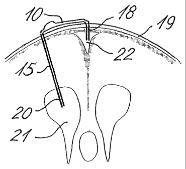
Figs. 6 and 7 show the principles of the location of the shunt device or
system. The shunt
body 10 is placed subcutaneously on the top of the calvarium, behind the
coronal suture
on the right (or left) side of the sagittal suture, see Fig. 6. Via a bored
hole through the
scull 19 a catheter 20 is inserted in the right (or left) ventricle 21 and via
the ventricular
drain or silicone rubber tube 15 it is connected to the shunt body 10. A small
hole (2-3 mm
in diameter) is bored through the scull 19 directly over the sagittal sinus
22, running in the
midline beneath the readily identifiable sagittal suture. The drain 18 of
substantially the
same outer diameter as the inner diameter of the borehole is introduced into
the sagittal
sinus 22 and is connected to the "distal" end of the shunt body 10. Suitable
ventricular
drains are well-known within the art, and the drain 15 can e.g. be a plain
silicone rubber
drain with an outer diameter of about 3 mm. Standard produced drains may be
preferred.
In Fig. 8 the sinus catheter is inserted in the transverse sinus. The shunt
body 10 is
placed subcutaneously between a frontal borehole for receiving the drain 15
and the
transverse sinus. The widest part of the transverse sinus is behind the ear of
the patient,
where an osseous prominence indicate the location. A borehole is made directly
over the
sinus, preferably by sing a trephine or a high-speed air drill.