Note: Descriptions are shown in the official language in which they were submitted.
CA 02421737 2003-03-12
TITLE: BR.I3Sk~ CA.ItD
FIELD OF THE INVENTION
The invention relates generally to brush cards for electric motoxs and
electric generators.
BtI.CKGROUNI) OF THE INVENTION
Electric motors generally consist of an axle holding an armature and
commutator which
are mounted in a housing. The housing contains a pair o~ f eld magnets (or
electro magnetic
windings, depending on the type o~ motor) which surround the armature.
Electric current is
supplied to the commutator by a pair of graphite/copper brushes. The brushes
are generally
mounted to the housing on a brush card. The brush card generally consists of a
flat card die-
stamped out o~ a paper based high pressure laminate, plastic or polyester
glass sheet, Zn a
majority of brush cards, the brushes are each carried in a hollow metal tube
which houses both a
brush and a biasing spring. 'The spring biases the brush towards the
commutator ensurhag the
brush makes electrical contact with the coxnnxutator. The metal tube, which is
often referred to
as a brush tube; can be made of brass or steel, depending on the desired
durability and reliability
o~ the brush card assembly. The brush tubes are generally rectangular tubes
having an open
bottom, an open end and four Legs projecting from the bolt~m. The brush tubes
are attached to
the card by passing the legs of the cubes through holes punched in the brush
card and then
crimping the portions of. the legs which extend pass the brush card. The
spring and the brushes
are then inserted into the brush tubes.
'ulhile the use of brush tubes has proven to be a reliable method o~ mounting
the brushes
CA 02421737 2003-03-12
to the brush card, there are several disadvantages with this construction.
Firstly, the added costs
associated with mounting the brush tubes to the brush cards axe not
inconsequential. If the brush
tubes are made of brass, the brush tubes alone will add several cents to the
material costs of
assembling the brush card. Furthermore, the steps of mounting the brush tubes
to the card and
S then inserting the spring and brush into the brush tube add to the cost of
manufacturing the brush
card. In addition to added cost, the brush tubes also adds a point of failure
to the finished brush
card assembly, increasing the possibility that the electric motor v~~Il fail
due to a poorly
assembled brush card cube. Furthermore, the brush tubes, being made of metal,
have a tendency
to conduct heat and, during the course of extended operatians, may became
overheated. The
I O overheated brush tubes may cause warping of the housing ox surrauzxding
brush card, causing the
brushes to jam. Also, the continual heating and cooling of the brush tubes can
cause the tubes to
become loose, resulting in a motor that fails to meet the required decibel
speaiftcations. An
improved brush card which is easier and Iess expensive to construct and which
does not suffer
from the drawbacks of existing brash cards is therefore desirable.
IS
SUMMARY OF°THE INVE1VTIC~N
In accordance with the present invention; fliers is provided a brush card
consisting of a non
conductive sheet material having a commutator aperture, and a pair of tongue
and groove
connector elements. Each tongue and groove connector element consisting of at
Ieast one pair of
20 parallel channels formed on the card adjacent the aperture and extending
along the card
perpendicular to the cammutator aperture, the card forming a pair of parallel
opposing channel
edges adjacent the parallel channels. A portion of the card forms an elongated
tongue separating
2
CA 02421737 2003-03-12
each pair of channels, the tongue having a distal end extending towards the
commutator aperture
and a proximal end opposite the clistal end. The brush card also includes a
conductive brush
slidingly mounted to each tongue, each brush having opposite first and second
sides and a central
groove dimensioned to receive the tongue. Each brush also has a fzrst groove
extending along
the first side of the brush, the fast groove dimensioned to receive one of the
channel edges. Each
brush also has a second groove extending along the second side of the brush,
the second groove
dimensioned to receive the other channel edge. The card further includes a
biasing spring located
on each tongue and positioned between the brush and the proxznaal end of the
tongue, the biasing
spring hissing the brash towards the commutator aperture.
With the foregoing in view, and other advantages as will become apparent to
those spilled
in the art to which this invention relates as this specifiaction proceeds, the
invention is herein
described by reference to the accompanying drawings foz~ning a part hereof,
which includes a
descxiption of the prefezxed typical embodiment of the principles of the
present invention..
T~ESCRIPTI4N tJF THE AI~.A,WINGS
FIGURE 1. is a top view of a brush card made in accordance with the present
invention.
FIGURE 2. is a top view of the brush card shown in figure 1 which does not
have the 'brushed
mounted thereto.
FIGURE 3, is an expanded top view of a portion of the brush card shown in
l~guxe 1.
ZO FIGURE 4. is an exploded view of the portion of the brash card shown zn
figure 3.
FIGURE 5, is a cross sectional view taken along line A-A of figure 3.
FIGURE 6. is a cross sectional view taken along line B-B of figure 3.
3
CA 02421737 2003-03-12
FIGURE 7. is a top view of a brush card having a slightly different tongue and
connector
elements.
FIGURE 8. is a top view of an alternate brush card made in accordance with the
present
invention.
In the drawings like characters of reference indicate corresponding parts in
the different
figures.
DETAILED DESCRIPTION CAF THE INVENTIc~lst
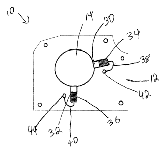
Referring firstly to figures 1 and 2 the brush card made in accordance with
the present
i 0 invention is shown generally as item 10 and consists of a substantially
planar card 12 die stamped
fram a non-conductive material such as paper based high pressure laminate, a
polyester glass
sheet, or injection molded plastic. Card 12 has a central aperture, referred
to as canvnutator
aperture 14, which is dimensioned to retain the comznutator of an electric
motor or generator (not
shown). Two pairs of tongue and groove connector elements 1 b and 1 ~ are
formed on card I 2
15 and extend perpendicular to commutator aperture 14. Connector 16 consists
of two parallel
channels 20 and 22 which extend perpendicularly from commutator aperture 14.
Tongue 24 is
formed between channels 20 and 22. Tongue 24 has distal end 2~ which extends
towards
commutator aperture 14. Tongue 24 also has proximal end 28 opposite the distal
end. Likewise,
connector 18 consists of two parallel channels 21 and 23 which extend
perpendicularly from
20 con~mutator aperture 14. Tongue 25 is formed between channels 21 and 24.
Tongue 25 'has
distal end 27 which extends towards commutator aperture 14. Tongue 2S also has
proximal end
29 ~pposite the distal end. Essentially, tongue and groove connector elements
16 and 1 ~ are
4
CA 02421737 2003-03-12
identical.
The brush card also includes electrical brushes 30 and 32 mounted to tongue
and groove
connector elements 15 and 18, respectively. Brushes 30 and 32 sJre biased
towards ape~rtuxe 14
by biasing springs 34 and 36, respectively. Finally, flexible electrical wires
38 and 40 electrically
couple brushes 30 and 32 with electrical terminals 42 and 44, respectively.
Referring now to figures 3 and 4, the details of how a brush is r~aou~ated
within its
respective tongue and groove connector element shall now be explained in
greater detail with
reference to tongue and groove connector element 16, brush 30 and biasing
spring 34. Brush 30
has opposite side walls 4f and 48. First groove SO is formed on side wall 46
of brush 30 and
second groove S2 is formed on side wall 48 ofbru.sh 30. Card I2 has edge 54
which extends
along groove 20 and edge 56 which extends along groove 22. Grooves 46 and 52
are
dimensioned and configured to retain edges ~4 and 56 when brush 30 is inserted
into connector
element 16. Brush 30 also has central groove SS formed between side walls 46
and 4$. Central
groove 58 is dimensioned and configured to receive tongue 24. Biasing spring
34 is a coil spring
which is dimensioned and configured to i~t onto tongue 24. When assembled,
biasing spring 34
is positioned on tongue 24 between ends 28 and 26. Tongue 24 has projections
60 and 62
adjacent proximal end 2$ which extend from the tongue into channels 22 and 20,
respectively.
Projections b0 and 62 are dimensioned to retain spring 34 on tonga~e 24 when
the spring is placed
onto tongue 24. Corresponding projections f4 and 66 are also formed on edges
~~ and ~4,
respectively, to ensure that the biasing spring is securely held in place when
the spring is paced
onto tongue 24. Projections 60, 62, 64 and 66 help retain spring 34 and
prevent it from being
accidentally dislodged off tongue 24 during brush card assembly. It will be
appreciated that
S
CA 02421737 2003-03-12
projections 60, 62, 64 and 66 may not always be required, since the tongue
locates and secures
the spzrinng, holding it in glare.
Referring now to figures 5 and 6, grooves 50 and 48 are coplanar with edges 54
and 56
and are dizxzensioned to receive the edges such that brush 30 can. slide back
and forth along edges
54 and 56. Tongue 24 and grove 58 are also coplanar with edges S4 and 56.
Tongue ~4 and
grove 58 ensure that brush 30 can slide back and forth without twisting and
catching on edges 54
ox 56. Electrical wire 3 $ is threaded through biasing spring 34 to permit a
more compact
arrangement. Alternatively, electrical wire 3~ may be connected to the brush
without passing
through biasing spring 34.
Referring back to fzgures 3 and 4, toxzgue 24 and groove 58 ezxsures that
bzvsh 30 can
slide back and forth in connector 16 without jamming. Brush 30 has an
electrical; contact face 68
which projects into commutaator aperture 14 and which, when assembled in an
electric motor,
makes electrical contact with the commutaxor (not shown). Since the commutator
rotates within
eommutator aperture 14, the eommutator rubs against electrical contact face 68
thereby applying
1 S torsional forces onto brush 30. These torsional farces may cause brush 30
to twist such that the
brush catches on edges 54 and 56. Since central groove 58 axed tongue 24 form
a tongue and
groove connection very close to the center of brush 30, they effectively
prevent brush 30 from
twisting as a result of the torsianal forces applied to the brush. Tongue 24
and groove 58 thereby
permit the brush to move back and fozrthh along connector 16 without jamming
onto edges S4 and
ZO SG. Tongue 24 also has the added benefit of acting as a convenient mounting
and retaining
meclaaniszn for biasing spring 34. If tongue 24 were not present, then biasing
spring 34 would
not be as secure2y mounted within connector element 16 and could fall out
during either
6
CA 02421737 2003-03-12
assembly ox operation.
Referring now to figure 7, an alternate embodiment of the present invention is
shown.
The alternate brush card, shown generally as item 100, consists of non-
conductive card 102
having commutator opening 104 and tongue and groove connector elements 106 and
108.
Tongue and groove cozanector elements 106 and 108 are identical. Both
connector elements have
parallel grooves 110 and 112 and elongated tongue 114 and edges 128 and 130
formed on the
card. Life the previous embodiment, tongue 114 has distal end 116 extending
towards
conunutator opening 104 and proximal end 118 opposite the dis~t~.I end. Unlike
the previous
embodiment, tongue 114 has first portion 122 adjacent the comznutator opening
and second
portion 120. Second portion 120 is wider than first :portion 122. Brush 124 is
mounted to first
portion 122 oftongue 114 and to edges 128 and 130 in a tongue and groove
fashion as in the
previous embodiment. Biasing spring I26 is mounted to second portion 120,
Since second
portion 120 is wider than first portion 122, biasing spring 126 can be nnore
securely held on the
tongue.
The present invention does away with the need for brush tubes. As a result,
tli~ brush
card is far less expensive to manufacture because it saves on the cost of the
tubes themselves and
also on the costs of assembling the brush tubes onto the brush card,
Refen~ng now to figure 8, an alternate embodiment of the brush card portion of
the
present invention is shown generally as item 200. As with the previous
embodiments, brush card
200 consists of a flat planar card made of a non-conductive material and
having a commutator
opening 210. Tongue and groove connector element 212 is formed on the card.
Like the
previous embodiments, tongue 214. forms part of tongue and groove connector
element 212.
7
CA 02421737 2003-03-12
LTnlil~e the previous embodiments, tongue 2I4 has a distal end 2I6 which does
not extend all the
way to commutator opening 210, leaving a gap 222 having opposing edges 21 ~
and 220. The
brush {not shown) can be slidingly mounted within gap 222 as in the previous
embodiments by
means of grooves on the sides of the brush which engage edges 220 and 21 ~.
Also as in the
S previous embodiments, the coil biasing spring (not shown) may be tbxeaded
onto tongue 21 ~ in
order to bias the bxush towards the commutator opening. In tbis design, since
t~ngue 2I4 does
not project into gap 222, the brash will not have to have a central groove in
order to
accommodate the tongue. This will be an advantage is vezy small electric
motors, where the
brushes are very small.
A specific embodiment of the present inventian has been disclosed; however,
several.
variations of the disclosed embodiment could be envisioned as within the scope
of this invention.
It is to be understood that the present invention is not limited to the
embodiments described
above, but encompasses any and all embodiments within the scope of the
following claims.
8