Language selection

Search

Patent 2421743 Summary

Third-party information liability

Some of the information on this Web page has been provided by external sources. The Government of Canada is not responsible for the accuracy, reliability or currency of the information supplied by external sources. Users wishing to rely upon this information should consult directly with the source of the information. Content provided by external sources is not subject to official languages, privacy and accessibility requirements.

Claims and Abstract availability

Any discrepancies in the text and image of the Claims and Abstract are due to differing posting times. Text of the Claims and Abstract are posted:

  • At the time the application is open to public inspection;
  • At the time of issue of the patent (grant).
(12) Patent Application: (11) CA 2421743
(54) English Title: A FLUID DISTRIBUTOR VALVE OUTLET OPENING AND CLOSING DEVICE
(54) French Title: DISPOSITIF D'OUVERTURE ET DE FERMETURE DE ROBINET D'UN DISTRIBUTEUR DE LIQUIDES
Status: Deemed Abandoned and Beyond the Period of Reinstatement - Pending Response to Notice of Disregarded Communication
Bibliographic Data
(51) International Patent Classification (IPC):
  • F16K 21/00 (2006.01)
  • F16K 11/16 (2006.01)
(72) Inventors :
  • RUIZ MELLADO, RAFAEL (Spain)
  • SERRANO SANCHEZ, EMILIO (Spain)
(73) Owners :
  • SACOPA, S.A.U.
(71) Applicants :
  • SACOPA, S.A.U. (Spain)
(74) Agent: SMART & BIGGAR LP
(74) Associate agent:
(45) Issued:
(22) Filed Date: 2003-03-12
(41) Open to Public Inspection: 2003-09-13
Availability of licence: N/A
Dedicated to the Public: N/A
(25) Language of filing: English

Patent Cooperation Treaty (PCT): No

(30) Application Priority Data:
Application No. Country/Territory Date
U 200200626 (Spain) 2002-03-13

Abstracts

English Abstract


A fluid distributor valve outlet opening and closing
device
This device comprises a body (2) having outlets (8),
and a bonnet (3) housing a rotor (6) being submitted to
the action of the inflowing fluid and being connected to
a reducing gear (15) activating the closing device. This
device is characterized in that the opening of said
outlets (8) is carried out with respective angularly
sliding shutters (9) being turned by means successively
shifting them in opposite directions to thus respectively
obtain the opening arid closing of said outlets (8). The
means shifting the shutters (9) are made up by studs (12,
13 and 14) being provided on the lower surface of the
rotary intermediary plate (4) being solid with the
reducing gear (15).


Claims

Note: Claims are shown in the official language in which they were submitted.

6
CLAIMS
1. A fluid distributor valve outlet opening and
closing device wherein said fluid distributor valves
comprise a body (2) having said outlets (8), and a bonnet
(3) housing a rotor (6) being submitted to the action of
the inflowing fluid and being connected to a reducing
gear (15) activating the closing device; characterized in
that the opening of said outlets (8) is carried out with
respective angularly sliding shutters (9) being turned by
means successively shifting them in opposite directions
to thus respectively obtain the opening and closing of
said outlets (8).
2. A device as per claim 1, characterized in that
the means shifting the shutters (9) are made up by studs
(12, 13 and 14) being provided an the lower surface of a
rotary intermediary plate (4) being solid with the
reducing gear (15).
3. A device as per claim 2, characterized in that in
the direction of rotation of the intermediary plate (4)
one (12) of said studs is a leading stud and pushes the
shutter (9) open whereas the other stud (14) being
arranged at a trailing position pushes the shutter (9)
closed.
4. A device as per claim 2, characterized in that
the edge of the shutter (9) being driven by said studs
(12, 13 and 14) is shaped with an angular configuration,
said studs respectively acting on one (16) and on the
other (16') of the sides forming said angular
configuration.
5. A device as per claim 1, characterized in that
the valve body (2) on which the shutters (9) slide is
provided with stops (17 and 18) restricting the angular
shift of said shutters in opposite directions.
6. A device as per claim 3, characterized in that
the leading stud is a double stud (12 and 13), the stud

7
(12) being more distant from the pin (10) embodying the
swiveling axis for the shutters (9) being the one acting
in the first place.
7. A device as per claim 1, characterized in that at
their mutually opposite openings the body (2) and the
bonnet (3) are provided with respective peripheral
flanges (2' and 3') being clasped by a clasp (25) joining
said body and bonnet together.
8. A device as per claims 1 and 2, characterized in
that the intermediary plate (4) is provided on its lower
surface with a collar being formed by two lengths (19)
and (19') and extending on top of the shutters (9) to
thus prevent them from rising, said collar guiding said
shutters by acting on the upper stud (30) being provided
on them, the action of the collar on said studs (30)
assuring that all of the outlets (8) but one will be
closed.
9. A device as per claim 1, characterized in that a
low-friction bushing is fitted to the lower edge of the
shutters (9) and thus facilitates the sliding of said
shutters on the body (2).

Description

Note: Descriptions are shown in the official language in which they were submitted.


CA 02421743 2003-03-12
1
TITLE OF INVENTION
A fluid distributor valve outlet. opening and closing
device.
FIELD OF THE INVENTION
The invention relates to a fluid distributor valve outlet
opening and closing device.
BACKGROUND OF THE INVENTION
Distributor valves are already known which are
preferably applied in connection with swimming pool
bottom flushing devices and comprise a chamber being made
up between a body and a bonnet, said body having a water
inlet port and several water outlets comprising closure
members being actuated by means of a reducing gear acting
by virtue of the action of the inflowing water on a rotor
cooperating with said gear.
The device being the object of this invention is
applicable to different models of valves of the above
mentioned type but more particularly consists in an
improvement on the valve being the object of the Spanish
Utility Model no. 200000421 (ES-1045405) of the very
Applicant, said valve comprising a central device by
means of which the passage of water towards the rotor as
well as its total obturation are controlled in order to
adjust the opening time for each outlet as well as the
time during which a given outlet will remain open and all
the other outlets wil l remain closed in the valve
passage.
In said Model no. 200000421 the closures of the
fluid outlets were made up by respective flaps being
hinged at one end and being raised at the opposite end by
means of a ramp being provided on the inside of the
bottom edge of the periphery of the intermediary plate,

CA 02421743 2003-03-12
2
this latter having fitted on its top surface the reducing
gear and being rotated by virtue of the meshing of the
reducing gear with an internal gear rim being provided on
the inner periphery of the bonnet.
BRIEF SUMMARY OF THE INVENTION
The device being the object of this invention
notably improves the opening and closing means for said
water outlets thereby reducing the force being needed to
actuate each shutter and using very simplified means.
The means being used to join and lock together the
body and bonnet have also been simplified and improved
since instead of for such a purpose using a bayonet lock
needing a safety catch a clasp is now used which clasps
the respective peripheral flanges being provided at the
mutually opposite openings of said body and bonnet.
This device is characterized in that said water
outlets are opened and closed wits respective shutters
being angularly slidable and being turned by means
successively shifting them in opposite directions in
order to thus respectively obtain the opening and closure
of said outlets, said means being made up by studs being
provided on the lower surface of the intermediary plate.
In the direction of rotation of the intermediary
plate one of said studs is a leading stud and pushes the
shutter open whereas the other stud being arranged at a
trailing position pushes the shutter closed, the stud-
driven edge of the shutter being shaped with an angular
configuration, said studs respectively acting on one and
on the other of the sides forming said angular
configuration.

CA 02421743 2003-03-12
3
BRIEF DESCRIPTION OF THE DRAWINGS
These and other characteristics will be best made
apparent by the following detailed description whose
understanding will be made easier by the accompanying two
sheets of drawings showing a practical embodiment cited
only by way of example not limiting the scope of the
present invention.
In the drawings:
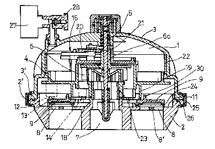
Fig. 1 is a sectional elevation of the assembly
forming a distributor valve comprising the device being
the object of this invention;
Fig. 2 is a plan-view of the valve body;
Fig. 3 shows a bottom plan-view of the intermediary
plate; and
Fig. 4 in a plan-view diagrammatically illustrates
the different stages in the operation of the device in
question.
DETAILED DESCRIPTION OF THE INVENTION
According to the drawings the device being the
object of the invention is applied to a distributor valve
having a chamber 1 being formed by a circular base body 2
being closed by means of a dome-shaped bonnet 3, an
intermediary plate 4 being rotatably fitted in said
chamber and surrounding an upright central shaft 5 being
also surrounded by a freely rotatable rotor 6 being
driven by virtue of the action of the water flowing into
the valve through a bottom port 7 being centrally
provided in body 2, this latter being provided around
said port with water outlets 8 being closed by closures
being made up by respective shutters 9 being angularly
slidable around a pin 10 being secured onto the upper
surface 11 of body 2.

CA 02421743 2003-03-12
4
Said shutters are turned by being actuated by means
successively shifting them in opposite directions to thus
respectively obtain the opening and closure of the
outlets 8, said means being made up by studs 12, 13 and
14 being provided on the lower surface of the
intermediary plate 4 being solid with the reducing gear
15. In the direction of rotation G of the plate 4 the
studs 12 and 13 of said studs are leading studs and push
the shutter 9 open, stud 12 being more distant from the
shutter swivel pin 10 being the ore acting in the first
place, whereas the stud 14 being arranged at a trailing
position pushes the shutter closed. The stud-driven edge
of the shutters is shaped with an angular configuration,
studs 12 and 13 acting on one (16) of the sides of said
angular configuration whereas stud 14 acts on the other
side 16'.
The angular shift of the shutters 9 is restricted in
both directions by a stop 17 being provided on the body 2
and by a neck 18 of said body being coaxial with the
bottom port 7, respectively. The intermediary plate 4 is
provided on its lower surface with an also coaxial collar
extending on top of the shutters 9 to thus prevent them
from rising.
This collar is formed by two lengths 19 and 19'
being separated from each other and also has the function
of guiding the shutters by acting on the stud 30 being
provided on their upper surface. The action of the collar
on the studs 30 assures at all times that all of the
outlets 8 but one will be closed. The first toothed wheel
20 of the reducing gear 15 meshes with a pinion 21 being
formed at the upper end of a tubular shaft 6a of the
rotor 6, whereas the last wheel (not shown) of said gear
meshes with a ring gear 22 being provided at the inner
periphery of the bonnet 3.

CA 02421743 2003-03-12
The above-mentioned valve comprises a central device
23 by means of which the passage of water from the bottom
port 7 towards the rotor 6 is controlled and can even be
totally shut off if desired in order to thus adjust the
5 opening time for the shutters 9, and also in order to
stabilize the opening of only one of these shutters when
arresting the valve.
In order to facilitate the sliding of the shutters 9
on the body 2 the lower edge of said shutters comprises a
low-friction bushing 24.
The body 2 and the bonnet 3 are joined and locked
together by means of a clasp 25 clasping the respective
flanges 2' and 3' being provided at the periphery of the
mutually opposite openings of said body and bonnet, an O
ring 26 being provided between said flanges.
Numeral 27 indicates the presence of a pressure
gage, and numeral 28 indicates the viewer bleed screw.
The water outlets 8 have a transversal tab 8'
facilitating the proper sliding of the shutters 9 on said
outlets, said shutters having in the vicinity of their
side 16 windows 29 aiding the passage of water towards
the outlets 8 when the shutters are opened.
The invention can within its essentiality be put
into practice in other embodiments only in detail
differing from the one having been described above only
by way of example, said other embodiments also falling
within the scope of the protection being sought.

Representative Drawing
A single figure which represents the drawing illustrating the invention.
Administrative Status

2024-08-01:As part of the Next Generation Patents (NGP) transition, the Canadian Patents Database (CPD) now contains a more detailed Event History, which replicates the Event Log of our new back-office solution.

Please note that "Inactive:" events refers to events no longer in use in our new back-office solution.

For a clearer understanding of the status of the application/patent presented on this page, the site Disclaimer , as well as the definitions for Patent , Event History , Maintenance Fee  and Payment History  should be consulted.

Event History

Description Date
Time Limit for Reversal Expired 2009-03-12
Application Not Reinstated by Deadline 2009-03-12
Inactive: Abandon-RFE+Late fee unpaid-Correspondence sent 2008-03-12
Deemed Abandoned - Failure to Respond to Maintenance Fee Notice 2008-03-12
Inactive: IPC from MCD 2006-03-12
Application Published (Open to Public Inspection) 2003-09-13
Inactive: Cover page published 2003-09-12
Letter Sent 2003-07-23
Inactive: Single transfer 2003-06-11
Inactive: First IPC assigned 2003-05-22
Inactive: Courtesy letter - Evidence 2003-04-08
Application Received - Regular National 2003-04-04
Filing Requirements Determined Compliant 2003-04-04
Inactive: Filing certificate - No RFE (English) 2003-04-04

Abandonment History

Abandonment Date Reason Reinstatement Date
2008-03-12

Maintenance Fee

The last payment was received on 2007-02-27

Note : If the full payment has not been received on or before the date indicated, a further fee may be required which may be one of the following

  • the reinstatement fee;
  • the late payment fee; or
  • additional fee to reverse deemed expiry.

Please refer to the CIPO Patent Fees web page to see all current fee amounts.

Fee History

Fee Type Anniversary Year Due Date Paid Date
Application fee - standard 2003-03-12
Registration of a document 2003-06-11
MF (application, 2nd anniv.) - standard 02 2005-03-14 2005-02-23
MF (application, 3rd anniv.) - standard 03 2006-03-13 2006-02-10
MF (application, 4th anniv.) - standard 04 2007-03-12 2007-02-27
Owners on Record

Note: Records showing the ownership history in alphabetical order.

Current Owners on Record
SACOPA, S.A.U.
Past Owners on Record
EMILIO SERRANO SANCHEZ
RAFAEL RUIZ MELLADO
Past Owners that do not appear in the "Owners on Record" listing will appear in other documentation within the application.
Documents

To view selected files, please enter reCAPTCHA code :


To view images, click a link in the Document Description column. To download the documents, select one or more checkboxes in the first column and then click the "Download Selected in PDF format (Zip Archive)" or the "Download Selected as Single PDF" button.

List of published and non-published patent-specific documents on the CPD .

If you have any difficulty accessing content, you can call the Client Service Centre at 1-866-997-1936 or send them an e-mail at CIPO Client Service Centre.


Document
Description 
Date
(yyyy-mm-dd) 
Number of pages   Size of Image (KB) 
Description 2003-03-12 5 218
Abstract 2003-03-12 1 23
Drawings 2003-03-12 2 124
Claims 2003-03-12 2 78
Representative drawing 2003-05-22 1 36
Cover Page 2003-08-20 1 66
Filing Certificate (English) 2003-04-04 1 169
Courtesy - Certificate of registration (related document(s)) 2003-07-23 1 106
Reminder of maintenance fee due 2004-11-15 1 110
Reminder - Request for Examination 2007-11-14 1 119
Courtesy - Abandonment Letter (Maintenance Fee) 2008-05-07 1 178
Courtesy - Abandonment Letter (Request for Examination) 2008-06-04 1 165
Correspondence 2003-04-04 1 24
Fees 2006-02-10 1 34
Fees 2007-02-27 1 34
Prosecution correspondence 2003-03-12 9 331