Sélection de la langue

Search

Sommaire du brevet 2421743 

Énoncé de désistement de responsabilité concernant l'information provenant de tiers

Une partie des informations de ce site Web a été fournie par des sources externes. Le gouvernement du Canada n'assume aucune responsabilité concernant la précision, l'actualité ou la fiabilité des informations fournies par les sources externes. Les utilisateurs qui désirent employer cette information devraient consulter directement la source des informations. Le contenu fourni par les sources externes n'est pas assujetti aux exigences sur les langues officielles, la protection des renseignements personnels et l'accessibilité.

Disponibilité de l'Abrégé et des Revendications

L'apparition de différences dans le texte et l'image des Revendications et de l'Abrégé dépend du moment auquel le document est publié. Les textes des Revendications et de l'Abrégé sont affichés :

  • lorsque la demande peut être examinée par le public;
  • lorsque le brevet est émis (délivrance).
(12) Demande de brevet: (11) CA 2421743
(54) Titre français: DISPOSITIF D'OUVERTURE ET DE FERMETURE DE ROBINET D'UN DISTRIBUTEUR DE LIQUIDES
(54) Titre anglais: A FLUID DISTRIBUTOR VALVE OUTLET OPENING AND CLOSING DEVICE
Statut: Réputée abandonnée et au-delà du délai pour le rétablissement - en attente de la réponse à l’avis de communication rejetée
Données bibliographiques
(51) Classification internationale des brevets (CIB):
  • F16K 21/00 (2006.01)
  • F16K 11/16 (2006.01)
(72) Inventeurs :
  • RUIZ MELLADO, RAFAEL (Espagne)
  • SERRANO SANCHEZ, EMILIO (Espagne)
(73) Titulaires :
  • SACOPA, S.A.U.
(71) Demandeurs :
  • SACOPA, S.A.U. (Espagne)
(74) Agent: SMART & BIGGAR LP
(74) Co-agent:
(45) Délivré:
(22) Date de dépôt: 2003-03-12
(41) Mise à la disponibilité du public: 2003-09-13
Licence disponible: S.O.
Cédé au domaine public: S.O.
(25) Langue des documents déposés: Anglais

Traité de coopération en matière de brevets (PCT): Non

(30) Données de priorité de la demande:
Numéro de la demande Pays / territoire Date
U 200200626 (Espagne) 2002-03-13

Abrégés

Abrégé anglais


A fluid distributor valve outlet opening and closing
device
This device comprises a body (2) having outlets (8),
and a bonnet (3) housing a rotor (6) being submitted to
the action of the inflowing fluid and being connected to
a reducing gear (15) activating the closing device. This
device is characterized in that the opening of said
outlets (8) is carried out with respective angularly
sliding shutters (9) being turned by means successively
shifting them in opposite directions to thus respectively
obtain the opening arid closing of said outlets (8). The
means shifting the shutters (9) are made up by studs (12,
13 and 14) being provided on the lower surface of the
rotary intermediary plate (4) being solid with the
reducing gear (15).

Revendications

Note : Les revendications sont présentées dans la langue officielle dans laquelle elles ont été soumises.


6
CLAIMS
1. A fluid distributor valve outlet opening and
closing device wherein said fluid distributor valves
comprise a body (2) having said outlets (8), and a bonnet
(3) housing a rotor (6) being submitted to the action of
the inflowing fluid and being connected to a reducing
gear (15) activating the closing device; characterized in
that the opening of said outlets (8) is carried out with
respective angularly sliding shutters (9) being turned by
means successively shifting them in opposite directions
to thus respectively obtain the opening and closing of
said outlets (8).
2. A device as per claim 1, characterized in that
the means shifting the shutters (9) are made up by studs
(12, 13 and 14) being provided an the lower surface of a
rotary intermediary plate (4) being solid with the
reducing gear (15).
3. A device as per claim 2, characterized in that in
the direction of rotation of the intermediary plate (4)
one (12) of said studs is a leading stud and pushes the
shutter (9) open whereas the other stud (14) being
arranged at a trailing position pushes the shutter (9)
closed.
4. A device as per claim 2, characterized in that
the edge of the shutter (9) being driven by said studs
(12, 13 and 14) is shaped with an angular configuration,
said studs respectively acting on one (16) and on the
other (16') of the sides forming said angular
configuration.
5. A device as per claim 1, characterized in that
the valve body (2) on which the shutters (9) slide is
provided with stops (17 and 18) restricting the angular
shift of said shutters in opposite directions.
6. A device as per claim 3, characterized in that
the leading stud is a double stud (12 and 13), the stud

7
(12) being more distant from the pin (10) embodying the
swiveling axis for the shutters (9) being the one acting
in the first place.
7. A device as per claim 1, characterized in that at
their mutually opposite openings the body (2) and the
bonnet (3) are provided with respective peripheral
flanges (2' and 3') being clasped by a clasp (25) joining
said body and bonnet together.
8. A device as per claims 1 and 2, characterized in
that the intermediary plate (4) is provided on its lower
surface with a collar being formed by two lengths (19)
and (19') and extending on top of the shutters (9) to
thus prevent them from rising, said collar guiding said
shutters by acting on the upper stud (30) being provided
on them, the action of the collar on said studs (30)
assuring that all of the outlets (8) but one will be
closed.
9. A device as per claim 1, characterized in that a
low-friction bushing is fitted to the lower edge of the
shutters (9) and thus facilitates the sliding of said
shutters on the body (2).

Description

Note : Les descriptions sont présentées dans la langue officielle dans laquelle elles ont été soumises.

CA 02421743 2003-03-12
1
TITLE OF INVENTION
A fluid distributor valve outlet. opening and closing
device.
FIELD OF THE INVENTION
The invention relates to a fluid distributor valve outlet
opening and closing device.
BACKGROUND OF THE INVENTION
Distributor valves are already known which are
preferably applied in connection with swimming pool
bottom flushing devices and comprise a chamber being made
up between a body and a bonnet, said body having a water
inlet port and several water outlets comprising closure
members being actuated by means of a reducing gear acting
by virtue of the action of the inflowing water on a rotor
cooperating with said gear.
The device being the object of this invention is
applicable to different models of valves of the above
mentioned type but more particularly consists in an
improvement on the valve being the object of the Spanish
Utility Model no. 200000421 (ES-1045405) of the very
Applicant, said valve comprising a central device by
means of which the passage of water towards the rotor as
well as its total obturation are controlled in order to
adjust the opening time for each outlet as well as the
time during which a given outlet will remain open and all
the other outlets wil l remain closed in the valve
passage.
In said Model no. 200000421 the closures of the
fluid outlets were made up by respective flaps being
hinged at one end and being raised at the opposite end by
means of a ramp being provided on the inside of the
bottom edge of the periphery of the intermediary plate,

CA 02421743 2003-03-12
2
this latter having fitted on its top surface the reducing
gear and being rotated by virtue of the meshing of the
reducing gear with an internal gear rim being provided on
the inner periphery of the bonnet.
BRIEF SUMMARY OF THE INVENTION
The device being the object of this invention
notably improves the opening and closing means for said
water outlets thereby reducing the force being needed to
actuate each shutter and using very simplified means.
The means being used to join and lock together the
body and bonnet have also been simplified and improved
since instead of for such a purpose using a bayonet lock
needing a safety catch a clasp is now used which clasps
the respective peripheral flanges being provided at the
mutually opposite openings of said body and bonnet.
This device is characterized in that said water
outlets are opened and closed wits respective shutters
being angularly slidable and being turned by means
successively shifting them in opposite directions in
order to thus respectively obtain the opening and closure
of said outlets, said means being made up by studs being
provided on the lower surface of the intermediary plate.
In the direction of rotation of the intermediary
plate one of said studs is a leading stud and pushes the
shutter open whereas the other stud being arranged at a
trailing position pushes the shutter closed, the stud-
driven edge of the shutter being shaped with an angular
configuration, said studs respectively acting on one and
on the other of the sides forming said angular
configuration.

CA 02421743 2003-03-12
3
BRIEF DESCRIPTION OF THE DRAWINGS
These and other characteristics will be best made
apparent by the following detailed description whose
understanding will be made easier by the accompanying two
sheets of drawings showing a practical embodiment cited
only by way of example not limiting the scope of the
present invention.
In the drawings:
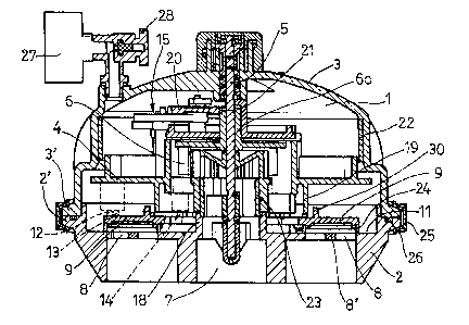
Fig. 1 is a sectional elevation of the assembly
forming a distributor valve comprising the device being
the object of this invention;
Fig. 2 is a plan-view of the valve body;
Fig. 3 shows a bottom plan-view of the intermediary
plate; and
Fig. 4 in a plan-view diagrammatically illustrates
the different stages in the operation of the device in
question.
DETAILED DESCRIPTION OF THE INVENTION
According to the drawings the device being the
object of the invention is applied to a distributor valve
having a chamber 1 being formed by a circular base body 2
being closed by means of a dome-shaped bonnet 3, an
intermediary plate 4 being rotatably fitted in said
chamber and surrounding an upright central shaft 5 being
also surrounded by a freely rotatable rotor 6 being
driven by virtue of the action of the water flowing into
the valve through a bottom port 7 being centrally
provided in body 2, this latter being provided around
said port with water outlets 8 being closed by closures
being made up by respective shutters 9 being angularly
slidable around a pin 10 being secured onto the upper
surface 11 of body 2.

CA 02421743 2003-03-12
4
Said shutters are turned by being actuated by means
successively shifting them in opposite directions to thus
respectively obtain the opening and closure of the
outlets 8, said means being made up by studs 12, 13 and
14 being provided on the lower surface of the
intermediary plate 4 being solid with the reducing gear
15. In the direction of rotation G of the plate 4 the
studs 12 and 13 of said studs are leading studs and push
the shutter 9 open, stud 12 being more distant from the
shutter swivel pin 10 being the ore acting in the first
place, whereas the stud 14 being arranged at a trailing
position pushes the shutter closed. The stud-driven edge
of the shutters is shaped with an angular configuration,
studs 12 and 13 acting on one (16) of the sides of said
angular configuration whereas stud 14 acts on the other
side 16'.
The angular shift of the shutters 9 is restricted in
both directions by a stop 17 being provided on the body 2
and by a neck 18 of said body being coaxial with the
bottom port 7, respectively. The intermediary plate 4 is
provided on its lower surface with an also coaxial collar
extending on top of the shutters 9 to thus prevent them
from rising.
This collar is formed by two lengths 19 and 19'
being separated from each other and also has the function
of guiding the shutters by acting on the stud 30 being
provided on their upper surface. The action of the collar
on the studs 30 assures at all times that all of the
outlets 8 but one will be closed. The first toothed wheel
20 of the reducing gear 15 meshes with a pinion 21 being
formed at the upper end of a tubular shaft 6a of the
rotor 6, whereas the last wheel (not shown) of said gear
meshes with a ring gear 22 being provided at the inner
periphery of the bonnet 3.

CA 02421743 2003-03-12
The above-mentioned valve comprises a central device
23 by means of which the passage of water from the bottom
port 7 towards the rotor 6 is controlled and can even be
totally shut off if desired in order to thus adjust the
5 opening time for the shutters 9, and also in order to
stabilize the opening of only one of these shutters when
arresting the valve.
In order to facilitate the sliding of the shutters 9
on the body 2 the lower edge of said shutters comprises a
low-friction bushing 24.
The body 2 and the bonnet 3 are joined and locked
together by means of a clasp 25 clasping the respective
flanges 2' and 3' being provided at the periphery of the
mutually opposite openings of said body and bonnet, an O
ring 26 being provided between said flanges.
Numeral 27 indicates the presence of a pressure
gage, and numeral 28 indicates the viewer bleed screw.
The water outlets 8 have a transversal tab 8'
facilitating the proper sliding of the shutters 9 on said
outlets, said shutters having in the vicinity of their
side 16 windows 29 aiding the passage of water towards
the outlets 8 when the shutters are opened.
The invention can within its essentiality be put
into practice in other embodiments only in detail
differing from the one having been described above only
by way of example, said other embodiments also falling
within the scope of the protection being sought.

Dessin représentatif
Une figure unique qui représente un dessin illustrant l'invention.
États administratifs

2024-08-01 : Dans le cadre de la transition vers les Brevets de nouvelle génération (BNG), la base de données sur les brevets canadiens (BDBC) contient désormais un Historique d'événement plus détaillé, qui reproduit le Journal des événements de notre nouvelle solution interne.

Veuillez noter que les événements débutant par « Inactive : » se réfèrent à des événements qui ne sont plus utilisés dans notre nouvelle solution interne.

Pour une meilleure compréhension de l'état de la demande ou brevet qui figure sur cette page, la rubrique Mise en garde , et les descriptions de Brevet , Historique d'événement , Taxes périodiques et Historique des paiements devraient être consultées.

Historique d'événement

Description Date
Le délai pour l'annulation est expiré 2009-03-12
Demande non rétablie avant l'échéance 2009-03-12
Inactive : Abandon.-RE+surtaxe impayées-Corr envoyée 2008-03-12
Réputée abandonnée - omission de répondre à un avis sur les taxes pour le maintien en état 2008-03-12
Inactive : CIB de MCD 2006-03-12
Demande publiée (accessible au public) 2003-09-13
Inactive : Page couverture publiée 2003-09-12
Lettre envoyée 2003-07-23
Inactive : Transfert individuel 2003-06-11
Inactive : CIB en 1re position 2003-05-22
Inactive : Lettre de courtoisie - Preuve 2003-04-08
Demande reçue - nationale ordinaire 2003-04-04
Exigences de dépôt - jugé conforme 2003-04-04
Inactive : Certificat de dépôt - Sans RE (Anglais) 2003-04-04

Historique d'abandonnement

Date d'abandonnement Raison Date de rétablissement
2008-03-12

Taxes périodiques

Le dernier paiement a été reçu le 2007-02-27

Avis : Si le paiement en totalité n'a pas été reçu au plus tard à la date indiquée, une taxe supplémentaire peut être imposée, soit une des taxes suivantes :

  • taxe de rétablissement ;
  • taxe pour paiement en souffrance ; ou
  • taxe additionnelle pour le renversement d'une péremption réputée.

Veuillez vous référer à la page web des taxes sur les brevets de l'OPIC pour voir tous les montants actuels des taxes.

Historique des taxes

Type de taxes Anniversaire Échéance Date payée
Taxe pour le dépôt - générale 2003-03-12
Enregistrement d'un document 2003-06-11
TM (demande, 2e anniv.) - générale 02 2005-03-14 2005-02-23
TM (demande, 3e anniv.) - générale 03 2006-03-13 2006-02-10
TM (demande, 4e anniv.) - générale 04 2007-03-12 2007-02-27
Titulaires au dossier

Les titulaires actuels et antérieures au dossier sont affichés en ordre alphabétique.

Titulaires actuels au dossier
SACOPA, S.A.U.
Titulaires antérieures au dossier
EMILIO SERRANO SANCHEZ
RAFAEL RUIZ MELLADO
Les propriétaires antérieurs qui ne figurent pas dans la liste des « Propriétaires au dossier » apparaîtront dans d'autres documents au dossier.
Documents

Pour visionner les fichiers sélectionnés, entrer le code reCAPTCHA :


Pour visualiser une image, cliquer sur un lien dans la colonne description du document. Pour télécharger l'image (les images), cliquer l'une ou plusieurs cases à cocher dans la première colonne et ensuite cliquer sur le bouton "Télécharger sélection en format PDF (archive Zip)" ou le bouton "Télécharger sélection (en un fichier PDF fusionné)".

Liste des documents de brevet publiés et non publiés sur la BDBC .

Si vous avez des difficultés à accéder au contenu, veuillez communiquer avec le Centre de services à la clientèle au 1-866-997-1936, ou envoyer un courriel au Centre de service à la clientèle de l'OPIC.


Description du
Document 
Date
(aaaa-mm-jj) 
Nombre de pages   Taille de l'image (Ko) 
Description 2003-03-12 5 218
Abrégé 2003-03-12 1 23
Dessins 2003-03-12 2 124
Revendications 2003-03-12 2 78
Dessin représentatif 2003-05-22 1 36
Page couverture 2003-08-20 1 66
Certificat de dépôt (anglais) 2003-04-04 1 169
Courtoisie - Certificat d'enregistrement (document(s) connexe(s)) 2003-07-23 1 106
Rappel de taxe de maintien due 2004-11-15 1 110
Rappel - requête d'examen 2007-11-14 1 119
Courtoisie - Lettre d'abandon (taxe de maintien en état) 2008-05-07 1 178
Courtoisie - Lettre d'abandon (requête d'examen) 2008-06-04 1 165
Correspondance 2003-04-04 1 24
Taxes 2006-02-10 1 34
Taxes 2007-02-27 1 34
Correspondance de la poursuite 2003-03-12 9 331