Note: Descriptions are shown in the official language in which they were submitted.
CA 02421947 2003-03-11
WO 02/22762 PCT/EP01/10572
1
METHOD AND APPARATUS FOR QUENCHING THE COKE DRUM VAPOUR
LINE IN A COKER
The invention relates to coker units and their
operation, particularly in the quenching of the vapour
line running from coke drums to a fractionator in a coker
unit.
Flow rate in a coke drum vapour line is influenced by
several factors including quench injection rate, quench
oil properties, coke drum temperature, vapour rate and
pressure drop from the coke drums to the fractionator. In
prior systems, the actual rate of liquid flowing out of
the vapour line into the coker main fractionator varies
during the coking cycle. Prior systems result in either
of two undesirable conditions: (1) overquench, which
reduces yields and possibly reduces unit feed rates, or
(2) underquench, which leaves a vapour line without any
liquid to flush the line out into the main fractionator
and which will eventually shut down the coker as the
vapour line cokes. Once the line cokes to the point of
causing enough pressure drop from the coke drums to the
main fractionator such that all the liquid evaporates,
only a short time remains until the coker must be shut
down - a very expensive event. In the prior systems, the
quench cannot generally be adjusted to target its
contribution to the recycle ratio. One prior method, the
delta temperature control technique, could possibly
target a contribution of the recycle ratio; however, the
downstream temperature indicator (TI) must be located in
the common part of the vapour line near the fractionator
in order for this to work correctly. The problem with
putting a TI in this location is that, in all likelihood,
it will foul and become inaccurate. As described in the
CA 02421947 2006-08-25
2
present disclosure, a TI located at the coke drum vapour
line outlet into the fractionator is not accessible during
operation but is easily cleaned while decoking a drum.
Prior quench techniques do not consider pressure
differential between the coke drum and the fractionator.
In one aspect of the invention, there is provided a
delayed coker comprising: an active coke drum having a
pressure transducer for measuring the pressure within said
lo drum, said coke drum being adapted to receive hot
fractionator bottoms from a fractionator, to capture the
carbon from said bottoms and to pass vapours from said
bottoms to a vapour line; means for injecting a quench
liquid into said vapour line; a fractionator, adapted to
receive said vapours from said vapour line, to receive a
hydrocarbon feed material thereinto and having means for
measuring the pressure therein; a controller for receiving
pressure signals from said coke drum and said fractionator
and for calculating the pressure differential therebetween;
means for generating a signal representing the feed rate
supplied to said fractionator and supplying said signal to
said controller; and means within said controller for
evaluating said pressure differential and said feed flow
input rate data and generating, in response thereto, a
signal for controlling a selected amount of quench liquid
to be injected into said vapour line.
In another aspect of the invention, there is provided
in a delayed coker unit having a coke drum and a
fractionator connected by a vapour line, a method for
measuring and controlling the amount of flow of quench
CA 02421947 2006-08-25
2a
liquid injected into said vapour line, comprising the steps
of: measuring the pressure within said coke drum;
measuring the pressure within said fractionator; measuring
the total flow rate of a liquid feed supplied to said
fractionator; supplying, to a controller, said measured
pressures and said measured total flow rate of feed liquid
being supplied to said fractionator; using coke drum vapour
line thermodynamics to evaluate the relationship between
said pressure differential and said feed flow input rate
data; determining, from said relationship, the amount of
quench liquid which must be supplied to said vapour line in
order to maintain a desired flow rate of liquid through
said vapour line and into said fractionator; generating, in
response to said relationship, a signal for controlling a
selected amount of quench liquid which must be injected
into said vapour line in order to result in the desired
flow rate of liquid through said vapour line and into said
fractionator; and controlling the flow rate of quench
liquid injected in said vapour line by supplying said
generated signal to a supply valve for opening and closing
said valve in response to said generated signal.
The invention is a method and apparatus for quenching
the coke drum vapour line which runs from the coke drum to
the main fractionator in a coker unit. The unique part of
this improved quench system is that it uses both pressure
differential and unit feed rates to control quench rates
for a given quench oil and unit feed quality. If the
CA 02421947 2006-08-25
2b
composition of the coker feed or the quench oil changes
significantly, a new set of quench curves may be generated
to ensure proper quenching of the coke drum vapour line.
The purpose of quench is to prevent the drum vapour line
from plugging with carbon-based deposits. Plugging of the
vapour line causes a restriction in coker unit feed rates
and ultimately leads to severely limiting coker feed rates
until the plug is removed. In order to remove the vapour
line plug, shut down of the unit is required which results
in lost coker capacity, due to the gradual slowdown and
subsequent shutdown of the coker unit, and in significant
economic loss. A differential pressure control technique
is utilized to quench the drum vapours going to the
fractionator as opposed to a temperature, delta
temperature, uninsulated line or fixed flow rate control
technique as used in prior systems. Vapour line quench
control by differential pressure prevents over-quenching of
the vapour line during a coke drum switch, unit startup, or
slowdown as well as preventing under-quenching during drum
warm-ups. It improves the fractionator recovery time after
a drum switch and the overall liquid product yield during
the drum cycle which can be reduced by over-quenching. It
also prevents the vapour line from
CA 02421947 2003-03-11
WO 02/22762 PCT/EP01/10572
3
drying out at anytime, an under-quenched condition, as
long as the quench oil quality and conditions do not vary
significantly.
To overcome the above problems, a new delayed coker
unit and a new process have been developed based on
pressure differential and unit feed. Thus, the present
invention relates to a delayed coker design as described
in claim 1 and a new process as described in claim 3.
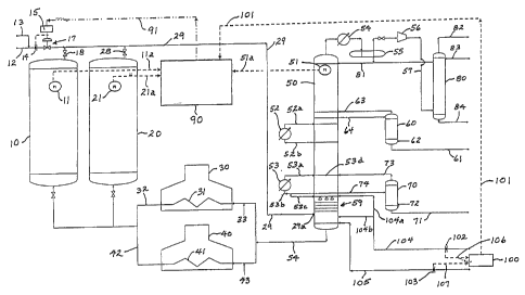
FIGURE 1 is a schematic drawing of a coker unit which
incorporates the instant invention.
FIGURE 2 is a graph showing quench flow vs. pressure
differential for the minimum and maximum feed rates for a
typical coker unit and coker feed quality.
The root cause of a coker vapour line plug is drying
out of the vapour line. In particular, during coke drum
warm-up, the vapour line may dry out due to the increased
pressure drop from the coke drum to the fractionator if
there is no increase in quench rate to prevent drying.
This added pressure drop can cause all of the liquid to
flash off inside the vapour line which leaves a layer of
carbon residue with entrained coke fines. To reduce the
risk of plugging the vapour line, the quench technique
disclosed herein adjusts quench rates based upon pressure
drop and unit feed rate. This delta pressure quench
control technique greatly reduces the potential of the
vapour line drying out and maintains a constant flow of
liquid flowing out the end of the vapour line into the
fractionator. It will generally increase yields vis-a-vis
the prior art delta temperature quench control (if the
vapour line temperature indicator (TI) is not located
near the fractionator), or the constant vapour
temperature quench flow technique, at a much reduced risk
of plugging the vapour line. These latter two prior art
techniques rely on over-quenching for most of the drum
cycle in order to prevent drying of the vapour line
CA 02421947 2003-03-11
WO 02/22762 PCT/EP01/10572
4
during drum warm-up. Or, if the TI is placed in an
inaccessible portion of the vapour line, the TI can foul
with coke and produce unreliable data, resulting in
under-quenching. If the delta temperature quench control
technique is to be reliable, accurate vapour line
temperatures near the coker main fractionator are
necessary; however, temperature indication in this
portion of the vapour line is inherently unreliable since
it is in this common portion of the vapour line where the
vapour line will likely foul, producing unreliable
temperature data. The fixed-quench rate vapour
temperature control may result in under-quenching and a
dry vapour line whenever a drum switch occurs, and this
can lead to the formation of a plugged vapour line.
The present invention overcomes three limitations of
the quenched vapour temperature control technique used in
prior systems: (1) the possibility of drying out the coke
drum vapour line; (2) the inferior reliability of
temperature indication in a coking environment to control
the quench rate, and (3) the essential over-quenching
necessary during most of the drum cycle if adequate
quench is to be supplied during drum warm-up, when the
pressure drop is usually at its highest. Also, the
accuracy of the drum pressure indicator is easily
verified during every drum cycle because the inactive
drum is opened to the atmosphere, therefore the pressure
indicator will read zero psig if working properly.
However, the temperature transducer can certainly foul
with coke, such that its accuracy is not easily verified
between drum cycles, due to the metal not having time to
cool to ambient verifiable conditions between cycles. Or
if the TI is located in the common portion of the vapour
line, one will not know if the TI is fouled, thus
producing unreliable data to control quench rates.
CA 02421947 2003-03-11
WO 02/22762 PCT/EP01/10572
In the following discussion, two coke drums are
illustrated and described. It will be appreciated that a
coker unit may comprise more than two coke drums.
Referring now to Figure 1, a typical coker unit comprises
5 two coke drums 10 and 20, two coker furnaces 30 and 40, a
main fractionator 50, a light gasoil stripper 60, a heavy
gasoil stripper 70 and possibly a rectified absorber 80,
all of which are known to those skilled in the art. In
the instant invention, a computer controller 90 is
additionally required to receive input data from the coke
drums 10, 20, the fractionator 50 and the input feed rate
indicator 100 and to generate control signals for
controlling quench flow rate as will be subsequently
described. Each of the coke drums 10, 20 contain pressure
transducers 11, 21, respectively, which monitor the
pressure inside the respective drums at all times and
relay such data to the controller 90. It will be
appreciated that, at any given time, one of the coke
drums will be "active" (on-line) and the other will be
off-line undergoing decoking and cleaning in preparation
for the next cycle, as is well known to those skilled in
the art. Likewise, the main fractionator 50 also includes
a pressure transducer 51 for constantly monitoring the
pressure therein and relaying such data to controller 90.
In operation, a cold feed heavy oil such as 6-Oil at
about 82 C (180 F) is fed through flow meter 102 and
line 104 to fractionator 50, via line 104a to grid
tray/spray unit 59 or via line 104b to the bottom of the
fractionator 50. Concurrently, a hot feed, such as hot
pitch at about 260 C (500 F) is fed through flow meter
103 and line 105 into the bottom of fractionator 50. Flow
meter signals from flow meters 102, 103 are relayed
through data lines 106, 107 respectively to the unit feed
flow indicator 100. The resulting flow signal is relayed
over data line 101 to the controller 90. The hot
CA 02421947 2003-03-11
WO 02/22762 PCT/EP01/10572
6
fractionator bottom stream is fed through line 54 to
furnaces 30, 40, after injecting velocity steam at 33,
43, respectively, where it is circulated through
tubes 31, 41, respectively, and heated up to about 488 C
(910 F). The bottoms must be severely thermally cracked,
otherwise it will not coke, and will, instead, form tar.
The hot fractionator bottoms exit the furnace tubes 31,
41 at 32, 42, respectively, at about 488 C (910 F) and
are directed to the active coke drum, either 10 or 20. In
the usual manner, the active coke drum 10 or 20 catches
and retains carbon matter while hydrocarbons evaporate.
It will be appreciated that this described apparatus is
called a"delayed coker" since it requires a combination
of residence time and temperature to form coke in the
coke drums 10, 20. Pressure transducers 11 and 21 relay
data over lines 11a and 21a respectively to the
controller 90. Vapour from the active coke drum 10 or 20
is passed through one of the valves 18, 28 to the
overhead coke drum vapour line 29. A quench liquid is
also injected into vapour line 29 through inputs 12 or
13, flow meter 14 and valve 17 to form a mixture of
quench oil and vapour in vapour line 29. Quench liquid 12
may be slop oil while quench liquid 13 may be a coker
gasoil. Quench liquid flow rate through vapour line 29 is
set by the quench flow indicator controller 15 which
regulates valve 17 in response to a signal received from
the controller 90 over control line 91 as will be
subsequently explained.
The quench oil/vapour mixture in vapour line 29 is
injected at the bottom of fractionator 50 at 29a, where,
in prior systems, a thermocouple may have been placed to
detect and relay temperature data and to possibly be used
for controlling the flow rate. As has been explained,
this temperature tended to be unreliable since the
thermocouple became coated with coke and became
CA 02421947 2003-03-11
WO 02/22762 PCT/EP01/10572
7
inaccurate. Main fractionator 50 includes a heavy gasoil
pump-around exchanger 53 for cooling vapours and removing
heat from the system. A circulation reflux unit also
includes a pump-around exchanger 52 for cooling vapours
and removing heat from the system further up the
column 50. Exchanger 52 receives hot circulating reflux
oil through line 52b and sends cooled circulating reflux
oil back to fractionator 50 through line 52a.
Exchanger 53 receives hot unstripped heavy gasoil through
line 53b, and part of the hot heavy gasoil can possibly
go back to the spray 59 through line 53c to prevent
entrained coke fines from escaping into the overhead
vapours. Cooled heavy gasoil from exchanger 53 is sent
back to the fractionator 50 via line 53a where it is
flowed onto tray 53d as part of the pumparound heat
removal system. Heavy gasoil stripper 70 receives
unstripped heavy gasoil from the fractionator 50 through
line 74 and steam is injected through line 72 to form
stripped heavy gasoil which is withdrawn by line 71.
Steam and stripped-out heavy gasoil is recirculated to
the fractionator 50 via line 73 where it flows onto
tray 53d. Line 53c is an alternate source of liquid for
spray 59 which, if used, reroutes the cold feed flowing
in line 104 to the bottom of the fractionator 50 via
line 104b along with the hot pitch through line 105.
Spray unit/contacting trays 59 prevent entrained coke
fines from escaping into the overhead vapours.
Light gasoil stripper 60 may be used for receiving
light unstripped gasoil through line 64 and steam through
line 62. Light stripped gasoil is produced and is
withdrawn through line 61 while the remaining vapours are
sent back to the fractionator 50 through line 63. The
overhead vapours in fractionator 50 are passed on to the
overhead condenser 54 which removes heat from the
overhead vapours. The condensed liquid passes to an
CA 02421947 2003-03-11
WO 02/22762 PCT/EP01/10572
8
accumulator 55 and wet gas compressor 56 compresses the
wet gasses, such as methane, ethane, propane, and butane.
The output of wet gas compressor 56 is transported
through line 57 to the rectified absorber (RA) 80 where
fuel gas is withdrawn at 82 and coker naphtha at 84, the
latter being sent to a hydrotreating unit. The
absorber 80 receives a lean oil input 83 which assists in
the separation of ethane from propane. Line 81 contains
the overhead liquid hydrocarbons that have been condensed
in the overhead condenser 54. These liquids are either
sent back to the main fractionator 50 as reflux or to the
RA 80. Pressure transducer 51 continuously transmits the
pressure inside fractionator 50 to the controller 90 over
line 51a.
As noted, the controller 90 receives continuous
pressure signals from pressure transducers 11, 21 in coke
drums 10, 20, respectively, and from pressure
transducer 51 in fractionator 50, even from the off-line
drum being decoked. The controller 90 also receives an
input feed rate signal 101 (in barrels per day) from unit
feed flow indicator 100. Controller 90 senses which of
the drums 10, 20 is active (on-line), since the pressure
in the off-line drum is lower than the pressure in the
on-line drum. It then calculates the difference in
pressure (DP) between the active drum (10 or 20) and the
fractionator 50 pressure transmitted by pressure
transducer 51. This DP is used by the controller 90,
along with the feed flow rate 101, to calculate the
quench flow rate which is required to be injected at 12,
13 in order to maintain a selected fresh feed liquid flow
percentage of, say 5 vol%, in vapour line 29 at point 29a
where the vapourline 29 intersects the main
fractionator 50. This is a very important area of the
vapour line to understand. If one does not understand
what influences the amount of liquid in the vapour line
CA 02421947 2003-03-11
WO 02/22762 PCT/EP01/10572
9
at this point, one could potentially (1) overquench,
i.e., too much liquid, which reduces liquid yields and
increases coker unit recycle to the main fractionator
bottoms and potentially could reduce coker unit
throughput or (2) underquench, i.e., too little liquid,
resulting in a dry, non-irrigated, vapour line which will
foul with coke and eventually shut down the coker unit.
Either one of these conditions is undesirable. A signal
is sent over line 91 to the quench flow indicator
controller 15 and valve 17 is automatically adjusted to
maintain such selected flow rate.
Quench rates needed to maintain a wetted line at
various vapour line pressure differentials, and unit feed
rates required to ensure a constant liquid rate flowing
out of the vapour line 29 into the coker main
fractionator 50 were calculated. A PRO/II general purpose
process and optimization software by Simulation Sciences,
Inc. was used to generate the data (PRO/II is a trade-
mark). This data is presented in Tables 1 and 2 below.
Tables 1 and 2 were obtained via computer simulation
of the coke drum vapour line thermodynamics. Based upon
the measured coker feed product yields and quench liquid
properties, a simulation was run to determine the quench
rate needed to produce a constant percentage of unit
recycle from liquid flowing out of the coke drum vapour
line into the bottom of the main fractionator. The vapour
line pressure drop was varied to determine the quench
rate needed to maintain constant liquid flow into the
main fractionator, while at premeasured product yields
and quench oil properties.
From Tables 1 and 2, the curves shown in Figure 2
were produced. Differential pressure drop (psi;
1 psi = 0.0689 bar) from the active coke drum to the main
fractionator is used as the X axis and quench rate (bpd)
as the Y axis. Once the curves are prepared for a
CA 02421947 2003-03-11
WO 02/22762 PCT/EP01/10572
particular coker, (for a given set of unit yields and
quench oil properties) such information is used to
control quench flows via computer control thereafter.
TABLE 1
Quench Flow Calculation for 5 Vol% Recycle based on
28,500 bpd Fresh Feed Rate
Drips (Liquid
Flowing out
of) - vapour Quench
DP - Quench Line into Temperature Drum
Differential Flow Main Frac - at Main Frac - Pressure
Pressure, psi BPD BPD F Psig
0 1200 1425 811 25
5 1633 1425 811 30
10 2025 1425 811 35
2383 1425 811 40
2714 1425 811 45
3307 1425 811 55
3831 1425 811 65
CA 02421947 2003-03-11
WO 02/22762 PCT/EP01/10572
11
TABLE 2
Quench Flow Calculation for 5 Vol% Recycle based on
14,500 bpd Fresh Feed Rate
Drips (Liquid
Flowing out
of) - vapour Quench
DP - Quench Line into Temperature Drum
Differential Flow Main Frac - at Main Frac - Pressure
Pressure, psi BPD BPD F Psig
0 602 725 810 25
818 725 810 30
1014 725 810 35
1193 725 810 40
1356 725 810 45
1656 725 810 55
1918 725 810 65
Note: Quench Oil temperature is assumed to be 100-150 F and
of a light gasoil boiling range hydrocarbon. If the
available quench oil is significantly different, another set
of tables may need to be produced.
Referring now to Figure 2, Tables 1 and 2 have been
displayed in graph form for the maximum (28.5 MBPD) and
minimum (14.5 MBPD) feed rates for a typical coker unit.