Note: Descriptions are shown in the official language in which they were submitted.
CA 02422118 2003-03-11
WO 02/22956 Al Support for a Track-Guided
PCTlEP01/10099 High Speed Vehicle
CBZ-913b (Revised)
WO 02/01/22956 Al
PCT/EPOI/10099
Support for a Track Guided
High Speed Vehicle
Description
The present invention concerns a support (hereinafter "beam") for a track
guided high
speed vehicle, especially a magnetically levitated railroad, wherein the beam
is supported
at intervals on piers and on the outer side of said beam, functional elements
are placed for
the guidance of a vehicle, in accord with the generic concept of Claim 1.
DE 41 15 935 C2, for example, has made known a carriageway construction for
magnetically levitated railroads, in which fittings for the guidance of a
vehicle are placed
on a beam and directed toward the inside. The beam itself is U-shaped, when
seen in
cross-section. The beam is supported on piers, whereby, for the better
acceptance of the
beam, holders are provided, in which the said beams lie. The holders extend
themselves
around the U-shaped cross-section on the outside and thus stabilize the beam.
The
holders themselves are in turn supported by bearing surfaces on the piers.
Disadvantageous in the case of such a carriageway is, that the beam, exhibits
a relatively
great degree of elasticity due to the open beam construction. Although the
equipment
placements must be very exactly aligned with each other in order to guide a
vehicle, with
this design of the carriageway, the satisfactory stabilization of the beam and
the
positioning of the equipment components is only possible with the aid of the
holder.
DE 38 25 508 C 1 discloses a carriageway which is comprised of a hollow,
essentially
T-shaped beam. On the outer sides of the upper flanges of the beam are placed
functional
elements for the guidance of a magnetically levitated vehicle. The beam itself
is again
supported on individual piers, whereby the piers possess holders, which grip
the bases of
the beam. Disadvantageous in the case of a beam of this type, is that although
the design
permits far more precise positioning of the functional elements to one another
than is
required by the a carriageway constructed according to DE 41 1 S 935, in spite
of this, still
the beam shows a poor torsion rigidity.
CA 02422118 2003-03-11
WO 02/22956A1 Support for a Track-Guided
PCTlEP01/10099 High Speed Vehicle
CBZ 913b (Revised)
This comes into effect particularly during extreme high speeds of a vehicle,
such as,
for instance, in excess of 500 km./h, often exhibiting itself as a rough ride
of a vehicle.
EP 0 987 370 Al discloses a carriageway for a magnetically levitated vehicle .
The
carnageway consists of a beam, upon which fastening means are mounted. The
beam is a
precast concrete structure, which, by means of attachment consoles, which are
placed on
the ends of the beam, is secured on support columns or piers. In its
longitudinal
direction, the beam itself, that is, except for the attachment consoles,
exhibits no change
in cross-section dimensioning. Such a beam has the disadvantage, that as the
vehicle
passes over the piers, very severe air turbulence occurs.
It is disadvantageous in the case of the above described embodiments of the
state of
the technology, that especially during the said high speeds of modern
magnetically
levitated vehicles, the flow resistance of the beams and their supporting
means prevent a
smooth run of a vehicle. Especially the holders of the beams or the piers, on
which the
beams are supported, cause periodic buffets on a vehicle, when the pressurized
air
encounters their resistance.
Thus the purpose of the invention is, to furnish, by means of an appropriate
adaptation of the beam to high speed magnetically levitated railroads, a
smooth and
comfortable run of magnetically levitated vehicles.
This purpose is achieved by the features of Claim 1.
If the outer surface of the beam is constructed with concern given to a
favorable
airflow in relation to a vehicle, wherein -- as seen in the longitudinal
direction of the
beam -- no cross-sectional changes occur, and the formation of the beam
predominately
covers the piers in relation to a vehicle, then, in an advantageous and
inventive manner,
the effect is that the air pushed away from a vehicle can uniformly escape and
thus a
smooth run of a vehicle is assured. By means of the invented design of the
beam, at the
same time, a uniform, comfortable run of a vehicle is effected. Because of the
fact, that
the cross-section of the beam predominately remains unchanged, no repeated
flow
impacts act against a vehicle. A uniform airflow is also brought about, in
that, in relation
to a vehicle, the piers are covered and thus the support of the beam does not
interfere with
CA 02422118 2003-03-11
WO 02/22956 A1 Support for a Track-Guided
PCTlEPOIl10099 High Speed Vehicle
CBZ 913b (Revised)
the escape of the pressurized air from a vehicle. This also contributes to a
uniform run of
a vehicle.
The beam is so designed, that it possesses a lower flange, which covers the
piers or
shields them in a favorable manner in respect to vehicle slipstream. When this
is done,
because of the shaping of the basic form of the beam, the airflow at any one
pier is
immediately slides by without impingement. In addition, or alternatively, it
can be
advantageous if the beam is equipped with a console essentially covering the
pier and
which console is shaped or located to be air-flow friendly.
It is of advantage, if the beam has at least one opening for the inspection of
its hollow
space. In this way, the accessibility and the monitoring of the reliability of
the beam will
be easier during the regularly scheduled inspections which are to be carned
out. Beyond
this, personnel can enter through the opening into the interior of the beam to
lay and
maintain supply lines and/or communication lines which are dependent on or
independent
of vehicle operation. By means of these uses of the hollow space of the beam,
a very
economical laying of lines can be carned out. Also, lines, which have nothing
to do with
the operation of a vehicle, can be laid along the now available stretch of the
magnetically
levitated railroad and thereby take advantage of a very economical kind of
line running.
Thus it can also be avoided, that separate beams need be installed, for
example for
communication lines or that these lines must be laid separately underground.
Advantageously, the beam has an airflow friendly clearance space for the
reception of
the guide elements, which the functional units of a vehicle occupy. This
clearance space
is designed to follow the beam in the flange area, without essential cross-
sectional
changing. In this way, the escape flow of vehicle displaced air is positively
influenced.
Moreover, essentially, an I-beam is created which possesses a particularly
high stability,
torsion resistance and load capacity.
The placement of the beam on the piers is advantageously done in such a
manner, that
the bearing elements are placed on the lower flange of the beam . The bearing
elements
as well as the piers are, in this way, covered over by means of the outwardly
extending
lower flange which covers said piers. Airflow impacts are avoided by this
measure.
CA 02422118 2003-03-11
WO 02/22956 A1 Support for a Track-Guided 4
PCTlEPOIl10099 High Speed Vehicle
CBZ-913b (Revised)
A particularly advantageous mode of construction of the beams is found
therein, in
that the beam is made of concrete, in particular out of precast concrete
components. By
this means, a very precise and error-free manufacture of the beam can be
carned out in a
fabrication plant. For instance, in this way, a dependency on weather
conditions during
the manufacture of the beam, such as site manufacture would entail, is
avoided.
In order to attain a particularly high degree of stability of the beam, it is
of advantage
if the lower flange is broader than the upper flange. For better rigidity of
the beam, it is
of advantage if it has a bulkhead or haunches.
The cross-sectional shape of the beam can, with this advantage, be made to
smaller
measurements but still maintain the same structural rigidity. If haunches are
placed in
the beam, then, besides the increased rigidity, also a simple anchorage-
possibility for
tensioning members is created.
Where curving is concerned, the beam advantageously forms a spatial curve, in
that
the beam is supported about a rotation of its longitudinal axis, and by means
of a
lengthening and/or a shortening of the cantilever arm, a radius is formed.
A further possibility for making the curve, would be that the upper flange of
the beam
be constructed in a rotation about its longitudinal axis and by means of
extending or
shortening the cantilever arm, a radius is formed.
A spatial curve of the beam can also be constructed in curve areas, in that
fastening
consoles of the functional elements in the run of the longitudinal axis of the
beam are
offset vertically and by the lengthening or the shortening of the fastening
consoles a
radius is built.
If the hollow space of the beam is open at the bottom, wherein the lower
flanges are
of two parts, than a less heavy and more economical beam is made, which
frequently can
fulfill the required demands in regard to structural rigidity.
If the hollow space possesses bulkheads, then the beam is additionally
stiffened.
Further advantages are to be acquired from the embodiments depicted in the
following. There is shown in:
Fig. 1 a cross-section through an invented beam,
Fig. 2 a cross-section through an invented canted beam,
CA 02422118 2003-03-11
WO 02/22956 A1 Support for a Track-Guided 5
PCTlEP01/10099 High Speed Vehicle
CBZ 913b (Revised)
Fig. 3 another cross-section through an invented beam,
Fig. 4 a cross-section through an invented beam for a curved section,
Fig. 5 a further cross section through an invented beam for a curved section,
Fig. 6 a perspective view of an invented beam, and
Fig. 7 a perspective view of a further invented beam.
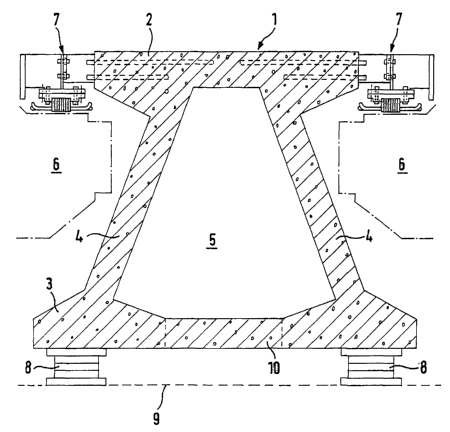
In Fig. 1 a cross-section of an invented beam 1 is presented. The beam 1 is
made
from a prefab concrete component and has an upper flange 2 and a lower flange
3. The
upper flange and lower flanges 2 and 3 are bound together by means of webs 4
and so
form a hollow space S. For entry of inspection personnel or for the laying of
lines in the
hollow space 5, an opening 10 is provided. One opening 10 per beam usually
suffices,
but preferably a plurality of openings 10 is favorable for simple
accessibility to the
hollow space 5. If a large number of openings 10 are provided, then this can
lead to a
clear reduction in the use of concrete and thus also lead to a more favorable
manufacturing cost for the beam 1.
The webs 4, in relation to the upper flange 2 and the lower flange 3, are
placed to
make a trapezoidal cross-section. This arrangement brings about a still better
support of
the beam 1 as well as contributing more to its stiffness than is achieved in
comparison
with the state of the technology. The beam, by means of this formation, is
extremely
torsion resistant and assures thereby a reliable and disturbance free
operation of a vehicle.
Between the upper flange 2 and the lower flange 3, a clearance space 6 is
allowed, in
which the guide components of the magnetically levitated vehicle can find
their place.
For the guidance of a vehicle, the functional elements 7 serve, which are to
be found on
both sides of the upper flange. The functional elements 7 are engaged by a
vehicle,
where by the under part of a vehicle is to be found in the area of the stator
in the
clearance space 6. By means of a non-changing cross-section of the beam 1,
which is not
disturbed by holders or bearing means, operation of a vehicle is made possible
having
favorable airflow and no repetitive impacts.
The beam 1 is, in the present embodiment, placed on bearing legs 8 which are
on the
piers 9. The piers 9 are, in this arrangement, in the area of the airflow-
relevant zone
CA 02422118 2003-03-11
WO 02/22956 Al Support for a Track-Guided
PCTlEP01/10099 High Speed Vehicle
CBZ 913b (Revised)
completely covered by the lower flange 3 of the beam 1 and thus generate no
disturbance
of the pressurized air from the passage of a vehicle.
The invented shaping of the beam 1 provides, besides the above mentioned
advantages, a particularly high transverse structural rigidity, and thus
assures a
comfortable and reliable operation of a vehicle. Especially because of the
layout, in
which the lower flange 3 is constructed broader than the upper flange 2, a
particularly
good stability of the beam 1 is assured. The consumption of material for the
invented
beam 1, which is high in comparison to that of the state of the technology, is
compensated for by the increased favorable airflow characteristics and the
energy saving
in operation of the vehicle which the beam 1 allows.
By means of this shaping, in particular that of the lower flange 3, of which
the upper
side is sharply inclined, the entire surface of the beam 1 is so designed that
a favorable
handling of the slipstream of air away from the beam 1 is attained. The piers
9 are
likewise subject to airflow but scarcely affect the dissipation of the escape
of the
pressurized air.
In Fig. 2, another beam 1 is depicted, which is similar to the beam 1 of Fig.
1. This
beam 1 is presented in a canted position, which means, that for a bow-shaped
carriageway, the two functional elements 7 display different heights. In this
case, the
curve travel for the magnetically levitated vehicle is enabled to be faster
and more
comfortable. The canting is so brought about, that the beam 1 is not seated
directly on
the load bearings 8, but, that load bearing consoles 12 are supplied, which
create the
banked position. The piers 9, as well as the thereupon located load bearings
8, thus act
together direct with the load bearing consoles 12 and only indirectly with the
beam 1,
This has the advantage that the manufacture of the piers 9 as well as the load
bearings 8
can be done without being dependent as to whether the carriageway is to run in
straight
line or be bow shaped. The compensation of the banked incline is done
exclusively by
the load bearing clamps 12. Alternatively, in any case provision may be made,
that the
piers 8 themselves take on the inclination and therewith the support of the
beam 1 in the
curves as well as in the straight section runs.
CA 02422118 2003-03-11
WO 02/22956 Al Support for a Track-Guided
PCTlEPOIl10099 High Speed Vehicle
CBZ 913b (Revised)
In Fig. 3 is shown a beam l, altered in contrast to the Figs. 1, 2. Also, in
this case the
banking of the beam for a bow shaped run is shown. The beam 1 comprises,
essentially a
rectangular cross-section with extending upper and lower flanges, respectively
2 and 3.
Also in this case, care has been taken as to the shaping of the beam 1, so
that repeated air
impacts during the passage of a magnetically levitated vehicle above are
avoided. The
air, which is pressurized by a vehicle in its slipstream is conducted away
over the shape
of the beam l, which allows a comfortable travel situation on a vehicle. For a
shaping of
the beam 1 of this kind, especially in the area of its webs 4, the clearance
area 6 for a
vehicle is especially well adapted to airflow. The gap between a vehicle and
the beam 1
is, as far as elevation is concerned, substantially even, so that even in this
aspect a
guidance of a vehicle employing streamline technology has been made possible.
Fig. 4 shows a differently designed beam 1. This beam 1 is clearly lower than
the
previously depicted beams. This becomes possible, in that the support space,
in which
this beam 1 was constructed was chosen to be essentially shorter. Experience
has shown,
that beam design, especially for travel in the curves, for which, in the case
of beam 1, i.e.
the fastening consoles of the function elements 7 must be adjusted, can be
done
essentially more favorably, if the individual beams 1 are made shorter. The
adjustment
on the individual beams is carned out essentially faster and with more
exactness due to
the shorter chord, which the beam 1 assumes in the carriageway bend. In
addition,
because of the shorter spacing intervals of the supports, to maintain an equal
rigidity of
the beam 1 a lesser height of the beam 1 is necessary, whereby, however,
construction
material is saved, when compared with that used in the case of the straight
sections.
While the beam, in accord with Fig. 4, corresponds in its fundamental shape to
the
beams of the Figs. l and 2, in a further embodiment shown in Fig. 5, the beam
has the
basic outline of Fig. 3. It presents the idea, that the beams in the Figs. 3
and 5 can be
combined with one another, and that the beams of the Figs. 1 or 2 and 4 can be
combined
with one another. The clearance way is, however, essentially the same for a
vehicle, so
that similar airflow relationships on the part of a vehicle exist both in
straight line travel
and in curve travel.
CA 02422118 2003-03-11
WO 02/22956 A1 Support for a Track-Guided
PCTlEP01/10099 High Speed Vehicle
CBZ 913b (Revised)
In the Figs. 6 and 7, are perspective presentations of beams 1 in accord with
the
invention, which are designed to be especially airflow favorable. In Fig. 6 a
beam 1 is
shown, which, over its entire length, the cross-section shape does not change.
Air pressure impacts on a vehicle by cross-sectional changes of the beam 1 are
thus
avoided. The loading consoles 12 in Fig. 7 are placed, in this case, deep on
the beam 1,
in order, that the airflow generated by the vehicle passing above can easily
escape, that is
to say, cannot act further upon a vehicle.
The beam 1 can also be so constructed, that its hollow space is left open at
the
bottom. The lower flange, in this case is then in two parts. The opening can
run
throughout the entire beam, or also be interrupted. In this case special
advantages are
gained in the manufacture of the beam 1, since the demolding of the beam 1 is
very easy
to carry out. A stiffening of such a beam 1 can be done by means of bottom
plates, which
simultaneous with the molding, or in retrofit fashion can be inserted or also
achieved by
the use of bulkheads. Instead of the beam with a hollow space, this design can
include
the beam being solid. The latter is particularly advantageous, if the beams be
installed on
bridges or primary construction operations andlor the beam lengths are shorter
than as is
intended for the usual stretches of the railroad.
The invention is not limited to the depicted embodiment. Also other beam
shapings,
which allow the air pressurized by a vehicle to be favorably left to escape
and essentially
no airstream impacts upon the passing of a vehicle near the piers are
generated are
objects of the invention.