Note: Descriptions are shown in the official language in which they were submitted.
CA 02422280 2003-03-17
DEVICE FOR DETECTING THE PRESENCE OF A CROP FLOW IN A
HARVESTING MACHINE
Field of the Invention
The invention relates to a device for detecting the presence of a crop flow in
a
harvesting machine with a sensor designed to emit an output signal containing
information on whether crop material is passing through the harvesting machine
or
not.
Background of the Invention
Sensors, for measuring the throughput of crops and based on different physical
principles, are used in harvesting machines for indicating the yield and/or
for yield
mapping. The sensors measure the crop throughput within certain error
tolerances.
In many systems, throughputs below a certain threshold value can no longer be
precisely measured. It is also conceivable, due to the error tolerances of the
sensors,
that throughputs are measured even though no crop is transported through the
harvesting machine.
Harvesting machines are, as a rule, also provided with so-called hectare or
acre
counters or meters used to measure the harvested area. They continue to count
a
measuring value representing the worked surface if a number of conditions have
been met, such as positive, i.e., forward, travel speed, front attachment in
harvesting
position, and if the crop processing and/or transport devices are in an
operating
mode. Since the presence of crop material is not checked, the harvested area
continues to be counted even if no flow of crop material is actually present.
Even
given a logical linkage to the signals of the sensors for measuring the crop
throughput, the corresponding information is not always correct, and results
in
incorrect area values.
The suggestion was therefore made to combine the sensor for measuring crop
throughput with a sensor for detecting the presence of a crop flow. To this
end, DE
199 03 471 C uses a light barrier in the discharge device of a field chopper.
A
measured value different from zero for the crop flow is emitted only if it
detects a
crop flow. However, the light barrier requires an additional structural
component
whose parts coming in contact with the crop flow wear down and can become
contaminated after being used for a rather long time.
Acoustic sensors are used in combines to detect lost grain. They detect
CA 02422280 2003-03-17
oscillations caused by lost grain falling onto impact plates or rods.
Summary of the Invention
The invention has the basic problem of making available an improved device for
the detection of the presence of a crop flow.
An object of the invention is to provide a harvesting machine incorporating a
crop
flow detecting device which detects vibrations produced during the processing
and/or
transporting of the crop flow in the harvesting machine.
The invention suggests detecting the presence or the absence of the crop flow
in
the harvesting machine acoustically. If a crop flow is present, it causes
noises
during the processing and/or during the transport in the harvesting machine.
The
sensor detects these noises, that is, mechanical or acoustic oscillations. The
desired
information about the presence of the crop flow is derived from the output
signal of
the sensor.
In this manner, the desired information is obtained by a sensor that can be
arranged outside of the crop flow, is not subject to any wear, and is not
contaminated
during operation.
Various embodiments can be considered as the sensor. It would be conceivable
to use a microphone that is advantageously arranged in the vicinity of a
location at
which the crop flow causes the highest possible noise level in order to allow
the best
possible differentiation from background noises. The microphone can detect the
vibrations purely by air sound, i.e., acoustically, or by body sound, i.e.,
mechanically.
It can, in particular, be a knocking sensor, like the one known in devices for
adjusting
the countercutting knife edge or shearbar in field choppers. It is also
conceivable to
use a sensor that detects the vibrations optically, e.g., with a laser beam
that strikes
elements that vibrate upon the presence of a crop flow. The reflected beam,
whose
direction is influenced by the vibrating elements, is detected by a position-
sensitive
detector.
The output signal of the sensor can also be used to control other elements of
the
harvesting machine. If, for exampie, a knocking sensor arranged on the
countercutting knife edge of a chopper drum is used, its output signal can be
used to
adjust the position of the countercutting knife edge as well as to verify a
crop flow. In
2
CA 02422280 2003-03-17
another embodiment, the sensor is arranged on the threshing concave of a
combine.
Its output signal can be used to adjust the slot of the threshing concave.
The sensor, in accordance with the invention, can be used in an area-detecting
device, a so-called hectare counter or acre meter, to differentiate the areas
on which
the actual harvesting is taking place from the remaining areas. The area is
only
counted if a crop flow is actually present.
The sensor can also be used in yield display devices and/or yield mapping
devices to only consider values referring to the amount of crop taken up when
the
sensor furnishes a signal indicating that a crop flow is actually present.
Otherwise,
the amount of yield is detected as zero. Such yield mapping devices generally
operate in a geo-referenced manner.
Brief Description of the Drawings
The drawings show two exemplary embodiments of the invention that are
described in detail in the following.
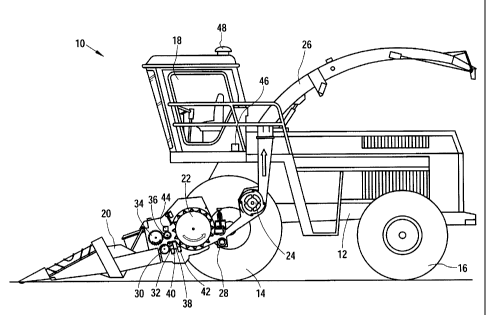
FIG. 1 is a somewhat schematic, left side elevational view of a field chopper.
FIG. 2 is a somewhat schematic, right side elevational view of a combine.
Description of the Preferred Embodiment
Referring now to FIG. 1, there is shown a harvesting machine 10 in the form of
a
self-propelled field chopper including a main frame 12 carried by front and
rear pairs
of wheels 14 and 16, respectively. The harvesting machine 10 is operated from
an
operator cab 18 located on a forward part of the frame 12 and from which one
can
view a crop pickup device 20. Crop material, e.g., corn, grass or the like
taken up
from the ground by the crop pickup device 20, is fed to a chopper drum 22,
that
chops the crop into small pieces and impels the crop to a transport device or
blower
24. The crop leaves the harvesting machine 10 to a trailer moving alongside
via
rotatable discharge spout 26. Comminuting device or kernel processor 28 is
located
between the chopper drum 22 and the transport device 24 and tangentially feeds
the
crop to be transported to transport device 24.
The crop is transported between crop pickup device 20 and the chopper drum 22
through lower compression rollers 30 and 32 and upper compression rollers 34
and
36. The knives distributed over the circumference of chopper drum 22 cooperate
with
3
CA 02422280 2003-03-17
countercutting knife edge or shearbar 38 in order to chop the crop.
Countercutting
knife edge 38 is provided with adjustment device 40 that is set to move
countercutting knife edge 38 in a horizontal direction toward, or away from,
the
chopper drum 22. It serves to adjust the cutting slot. A knocking sensor 42 is
arranged on the countercutting knife edge 28. It detects the noises caused by
the
knives of chopper drum 22 when countercutting knife edge 38 comes closer to
chopper drum 22. The output signals of the knocking sensor 42 are used in a
known
manner to adjust the position of countercutting knife edge 38.
A throughput sensor 44 is associated with the upper rear compression roller
36.
The compression roller 36 can be moved up by the crop against the force of a
spring. Throughput sensor 44 comprises a potentiometer that is adjusted upward
by
compression roller 36 during its movement. Thus, the throughput sensor 44
produces information about the particular throughput. The throughput sensor 44
is
connected to a computer 46 arranged in the operator cab 18, of which the
computer
is also connected to a position sensor 48, that is shown in the form of a GPS
antenna as an exemplary embodiment.
The computer 46 detects the signals of the throughput sensor 44 and of the
position sensor 48 during the harvesting and makes a geo-referenced yield map
and
also produces a yield display for the operator. An advance or travel speed
signal
can also be taken into consideration, thereby, that is produced by a known
sensor.
The yield signal can also be used for automatic control of the advance speed.
Since
the separation between upper rear compression rolier 36 and rear back
compression
roller 32 does not differ substantially or not at all, given small crop
throughputs, from
the separation that they assume when there is no throughput at all present,
throughput sensor 44 would actually display non-existent measured values in
the
case of low or lacking throughputs, which however, would be displayed and
mapped.
In order to improve the accuracy of the yield display and yield mapping, the
computer 46 is connected to the knocking sensor 42. Its analog output signals
are
digitized in the computer 46 or by a separate transducer. Knocking sensor 42
supplies an output signal whose amplitude and/or frequency contain information
about whether crop material is being processed or not at the time, since the
4
CA 02422280 2003-03-17
chopping of the crop material causes mechanical oscillations in the
countercutting
knife edge 38 that are picked up by the knocking sensor 42. The measured
values
supplied by throughput sensor 44 are only mapped as differing from zero if the
output signal of knocking sensor 42 indicates processed crop material. This
avoids
the above-described mapping errors.
Moreover, computer 46 detects the size of the area harvested by the harvesting
machine 10. The signal of the position sensor 48 is used for this. In an
analogous
manner, the computer 46 detects an area that has been traveled over as having
been harvested only when the output signal of the knocking sensor 42 indicates
that
crop material is being processed. Signals indicating the operating state of
the crop
pickup device 20 and of the chopper drum 22 can also be considered in the
detection of areas.
FIG. 2 illustrates a second embodiment of the invention that shows a
harvesting
machine 10 in the form of a self-propelled combine. It comprises a main frame
50
supported in a movable fashion by a wheel arrangement, comprising rear,
steerable
wheels 52 and front, driven wheels 54.
A vertically adjustable front harvesting attachment 56 with a mowing beam is
used to cut off standing crop material and supply cut material to an oblique
conveyor
58. The oblique conveyor 58 is pivotably connected to the main frame 50 and
comprises a conveying device for feeding the harvested material to a guide
drum 60.
The guide drum 60 conducts the material upward through the inlet transition
section
62 to a rotatable threshing and separating device 64. Other orientations and
types of
threshing devices and other types of front harvesting attachments 56, such as
transversally arranged frames carrying individual units in rows, could also be
used.
The rotating threshing and separating device 64 threshes and separates the
harvested crop. The grain and chaff fall through grates on the bottom of the
threshing and separating device 64 into a cleaning system 66. The cleaning
system
66 removes the chaff and conveys the clean grain to an elevator 68. The
elevator 68
for clean grain, deposits the clean grain in a grain tank 70. The clean grain
in the
grain tank 70 can be unloaded by an unloading auger 72 onto a truck or a
trailer.
Threshed, grain-free straw is fed from threshing and separating device 64
CA 02422280 2006-09-28
through an outlet to an ejection drum 74. The ejection drum 74 ejects the
straw at
the back of the combine 10. Note that the ejection drum 74 could also supply
the
material freed of grain directly to a straw chopper. The operation of the
harvesting
machine 10 is controlled from an operator cab 76.
The rotatable threshing and separating device 64 comprises a cylindrical rotor
housing 78 and a hydraulically driven rotor 80 arranged in a rotor housing 78.
The
front part of rotor 80 and rotor housing 78 define a loading section. A
threshing
section, separating section, and outlet section are downstream from the
loading
section. The rotor 80 is provided in the loading section with a conical rotor
drum
comprising helical loading elements for engaging into material that it
receives from
the guide drum 60 and from the inlet transition area 62. The threshing section
is
located immediately downstream from the loading section. In the threshing
section, rotor 80 comprises a cylindrical rotor drum provided with a number of
threshing elements in order to thresh the material received from the loading
section. The separating section is located downstream from the threshing
section,
in which separating section, the grain still caught in the threshed material
is set
free and falls through a bottom grate in the rotor housing 78 into the
cleaning
system 66. The separating section merges into an outlet section in which the
straw freed from the grain is ejected from the threshing and separating
device.
The throughput sensor 81 is in the form of a known impact plate sensor and is
arranged at the outlet of elevator 68 in the transition housing 82. The grain
coming out of the elevator 68 is transported on the bottom of the transition
housing 82 by the auger 84 into the grain 70. A computer 86 is electrically
connected to the throughput sensor 81 and a position sensor 88, shown here as
a
GPS antenna. The computer 86 can be operated during the harvesting operation,
and by using measured values of the throughput sensor 81, to prepare a geo-
referenced yield map and to display the instantaneous yield to the operator.
Since
the measured values of the throughput sensor 81 have a fair number of errors
in
the instance of relatively low yields, the computer 86 is connected to another
sensor 90 designed to detect whether a crop flow is present at all. The
measured
values of throughput sensor 81 are only viewed as differing from zero if the
sensor
90 indicates the presence of crop flow. Computer 86 can, as in the first
6
CA 02422280 2006-09-28
embodiment, detect the harvested area, during which the signals of the sensor
90
are considered in the described manner.
The sensor 90 is arranged on the threshing section of the rotor housing 78 of
the threshing and separating device 64. The sensor 90 is an acoustic sensor
and
detects mechanical vibrations generated by the crop during threshing. The
signals of sensor 90 are digitized and supplied to the computer 86. Using the
frequency and/or amplitude of the signals of sensor 90, computer 86 recognizes
whether crop is being processed or not. The signals of sensor 90 can also be
used to automatically adjust the separation between the rotor 80 and the
threshing
concave.
It remains to be pointed out that the sensor 90 can also be associated with
tangentially loaded threshing drums of combines with straw shakers or of
combines with separating rotors arranged after a tangential threshing drum. In
each instance, this sensor detects the noises caused during the threshing of
crop
material.
Sensor 90 could also be arranged in the oblique conveyor 58 and detect
noises caused by the crop when striking edges or when passing any surface.
Such sensors are currently being used for detecting stone-like objects
(US 4,343,137 A).
Having described the preferred embodiment, it will become apparent that
various modifications can be made without departing from the scope of the
invention as defined in the accompanying claims.
7