Note: Descriptions are shown in the official language in which they were submitted.
CA 02422325 2003-03-13
WO 02/28516 PCT/AU01/01256
MULTI-PORT SEPARATION APPARATUS AND METHOD
Technical Field
This invention relates to an apparatus for separation of compounds in
solution by electrophoresis, a separation unit and cartridge suitable for the
apparatus, and methods of use of the apparatus.
Background of the Invention
Preparative scale electrophoretic separations are becoming important for
the processing of both simple and complex samples. A key element determining
the success of such separation is the extent to which convective re-mixing of
the
separated components can be prevented. Multicompartment electrolyzers are
considered attractive for preparative-scale electrophoretic separations
because
separated components of a sample can be readily isolated in space and/or time.
Many of the multicompartment electrolyzers suffer from the improper
integration
~5 of the electrophoretic and hydraulic transport trajectories. Recently, the
GradiflowT"" technology (US 5039386, Gradipore Limited) was introduced to
favorably implement the integration of the electrophoretic and hydraulic
processes involved in the preparative-scale electrophoretic separation of
components. Despite its favorable characteristics, the GradiflowT"" technology
2o was limited in the sense that it implemented two separation chambers
isolated
from each other and the electrode compartments by electrophoresis separation
membranes that essentially prevented convective mixing of the contents of
adjacent chambers. This design limited the GradiflowT"" technology to binary
separations, albeit by sequential binary separations, individual components
could
2s also be separated from complex mixtures.
The present inventors have now developed a multichamber electrolyzer
which extends the application field of separation technology from binary
separations to the simultaneous separation of multiple components from complex
mixtures.
CA 02422325 2003-03-13
WO 02/28516 PCT/AU01/01256
2
Disclosure of Invention
In a first aspect, the present invention provides a multi-port electrophoresis
apparatus, the apparatus comprising:
(a) a cathode chamber containing a cathode;
(b) an anode chamber containing an anode, wherein the anode chamber is
disposed relative to the cathode chamber so that the cathode and anode are
adapted to generate an electric field in an electric field area upon
application of a
selected electric potential between the cathode and anode;
(c) inlet and outlet means for communicating liquid into and out of the
cathode
chamber defining a catholyte flow path;
(d) inlet and outlet means for communicating liquid into and out of the anode
chamber defining an anolyte flow path;
(e) at least one electrolyte reservoir in fluid communication with the cathode
chamber and the anode chamber;
(f) means adapted for communicating at least one electrolyte between the
electrolyte reservoir and the cathode and anode chambers;
(g) at least three adjacently disposed separation chambers disposed between
the cathode and anode chambers so as to be at least partially disposed in the
electric field area, the separation chambers being formed by a plurality of
ion-
2o permeable barriers positioned between the anode and cathode chambers, the
ion-permeable barriers adapted to impede convective mixing of contents of
adjacent chambers;
(h) inlet and outlet means for communicating liquid into and out of the
separation chambers defining separation flow paths;
(i) at least one sample reservoir, wherein each at least one sample reservoir
is in fluid communication with at least one separation chamber; and
(j) means adapted for communicating fluids between a sample reservoir and
at least one separation chamber;
wherein application of the selected electric potential causes migration of at
least one component through at least one of the ion-permeable barriers.
Preferably, the apparatus comprises two electrolyte reservoirs, a catholyte
reservoir in fluid communication with the cathode chamber and an anolyte
reservoir in fluid communication with the anode chamber.
CA 02422325 2003-03-13
WO 02/28516 PCT/AU01/01256
Preferably, the apparatus comprises between four and twelve separation
chambers having between four and twelve corresponding sample reservoirs in
fluid .communication with a respective separation chamber. The apparatus can
have any number of separation chambers, preferably three, four, five, six,
seven,
eight, nine, ten, eleven, twelve or more. The apparatus can have any number of
sample reservoirs, preferably three, four, five, six, seven, eight, nine, ten,
eleven,
twelve or more. There can be one sample reservoir for each separation chamber
or a sample reservoir can be in fluid communication with more than one
separation chamber.
In one preferred form, the apparatus comprises six separation chambers
and six corresponding sample reservoirs in fluid communication with a
respective
separation chamber. In another preferred form, the apparatus comprises eight
separation chambers and eight corresponding sample reservoirs in fluid
communication with a respective separation chamber. In yet another preferred
form, the apparatus comprises twelve separation chambers and twelve
corresponding sample reservoirs in fluid communication with a respective
separation chamber.
Preferably, at least some of the barriers restrict convective mixing of
contents of adjacent chambers and prevent substantial movement of components
2o in the absence of an electric field.
In one preferred form, the barriers are membranes having characteristic
average pore sizes and pore size distributions.
In another preferred form, at least one of the barriers is an isoelectric
membrane having a characteristic p1 value.
In another preferred form, least one of the barriers is an ion-exchange
membrane capable of mediating selective movement of ions.
It will be appreciated that the apparatus can have the same type of ion-
permeable barrier or a combination of two or more types, depending on the
desired separation or treatment of a given sample.
3o Preferably, the cathode and anode electrodes comprise titanium mesh
coated with platinum.
In one preferred form, a separation chamber contains inlet and outlet
means that are in fluid communication with that chamber.
CA 02422325 2003-03-13
WO 02/28516 PCT/AU01/01256
4
In another preferred form, at least two separation chambers are in fluid
communication via the same inlet and outlet means.
In another preferred form, at least one separation chamber is in fluid
communication with at least one other separation chamber via an external fluid
communication means.
In another preferred form, at least two of the separation chambers are in
serial fluid communication.
In another preferred form, at least two of the separation chambers are in
parallel fluid communication.
1o The apparatus may further comprise:
means adapted for circulating electrolyte from the at least one electrolyte
reservoir through the cathode chamber and the anode chamber forming
electrolyte streams in the respective chambers; and
means adapted for circulating fluid content from the sample reservoirs
through the respective separation chambers forming separation streams in the
respective separation chambers.
Preferably, the means adapted for communicating the electrolyte and fluid
content comprise pumping means which are separately controlled for
independent movement of the respective electrolyte and fluid.
2o The apparatus may further comprise means adapted for removing contents
from and replacing contents in at least one of the sample reservoirs.
The apparatus may further comprise means adapted to maintain
temperature of contents in at least one of the cathode chamber, the anode
chamber, a sample reservoir, or a separation chamber. In one form, the
temperature of electrolyte in the cathode and anode chambers and/or fluid in
the
at least one of the separation chambers is maintained. Preferably, the means
to
maintain the temperature is a tube-in-shell heat exchanger.
In a preferred form of the apparatus, the cathode chamber, the anode
chamber and the separation chambers are contained in a separation unit wherein
so the separation unit is selected from the group consisting of a cartridge
and a
cassette and the separation unit is fluidly connected to the electrolyte
reservoir
and the sample reservoirs.
CA 02422325 2003-03-13
WO 02/28516 PCT/AU01/01256
In a second aspect, the present invention provides an electrophoresis
separation unit, the unit comprising:-
(a) a cathode chamber containing a cathode;
(b) an anode chamber containing an anode, wherein the anode chamber is
5 disposed relative to the cathode chamber so that the cathode and anode are
adapted to generate an electric field in an electric field area upon
application of a
selected electric potential between the cathode and anode;
(c) an inlet and outlet means for communicating liquid into and out of the
cathode chamber defining a catholyte flow path;
(d) an inlet and outlet means for communicating liquid into and out of the
anode chamber defining an anolyte flow path;
(e) at least three adjacently disposed separation chambers disposed between
the cathode and anode chambers so as to be at least partially disposed in the
electric field area, the separation chambers being formed by a plurality of
ion-
~5 permeable barriers positioned between the anode and cathode chambers, the
ion-permeable barriers adapted to impede convective mixing of contents of
adjacent chambers; and
(f) inlet and outlet means for communicating liquid into and out of the
separation chambers defining separation flow paths;
2o wherein application of the selected electric potential causes migration of
at least
one component through at least one of the ion-permeable barriers.
Preferably, the unit comprises between three and twelve separation
chambers. The unit can have any number of separation chambers, preferably
three, four, five, six, seven, eight, nine, ten, eleven, twelve or more.
25 In one preferred form, the unit comprises four separation chambers. In
another preferred from, the unit comprises six separation chambers. In a yet
further preferred form, the unit comprises twelve separation chambers. It will
be
appreciated, however, that any number of separation chambers can be
incorporated into the unit.
3o Preferably, at least some of the barriers restrict convective mixing of
contents of adjacent chambers and prevent substantial movement of components
in the absence of an electric field.
CA 02422325 2003-03-13
WO 02/28516 PCT/AU01/01256
Preferably, the barriers are membranes having characteristic average pore
sizes and pore size distributions.
In one preferred form, at least one of the barriers is an isoelectric
membrane having a characteristic p1 value.
s In another preferred form, at least one of the barriers is an ion-exchange
membrane capable of mediating selective movement of ions.
In another preferred form, the cathode and anode electrodes comprise
titanium mesh coated with platinum.
It will be appreciated that the unit can have the same type of ion-permeable
1o barrier or a combination of two or more types, depending on the desired
separation or treatment of a given sample.
In one form, the unit comprises a cathodic connection block and an anodic
connection block which define a plurality of inlet and outlet means for
communicating liquid into and out of the separation chambers.
15 In this form, the cathodic and anodic connection blocks preferably house
the cathode and anode and connection means for connecting the cathode and
anode to a power supply.
In one form, the cathode is housed in a recess or channel defined in the
cathodic connection block and the anode is housed in a recess or channel
2o defined in the anodic connection block. The anodic and cathodic connection
blocks also preferably define inlets and outlets for the catholyte and anolyte
flow.
In one preferred form, at least one separation chamber is in fluid
communication with at least one other separation chamber via an external
communication means.
2s In another preferred form, at least two separation chambers are in serial
fluid communication.
In another preferred form, at least two separation chambers are in parallel
fluid communication.
In another preferred form, at least two separation chambers are in fluid
3o communication via the same inlet and outlet means.
In a preferred form, the separation chambers are formed or housed in a
cartridge which is adapted to be removable from the unit.
In a third aspect, the present invention provides a cartridge for use in an
CA 02422325 2003-03-13
WO 02/28516 PCT/AU01/01256
7
electrophoresis unit, the cartridge comprising:
(a) a housing containing at least two inner ion-permeable barriers positioned
between a first outer ion-permeable barrier and a second outer ion-permeable
barrier, the barriers defining three or more separation chambers therebetween,
the barriers adapted to impede connective mixing of contents in adjacent
chambers; and
(b) inlet and outlet ports for communicating liquid into and out of the
chambers
defining flow paths in the separation chambers; wherein upon communication of
liquid to the inlet ports, liquid is caused to stream through the chambers
without
substantial connective mixing of liquid between the chambers.
Preferably, the cartridge further includes external gaskets positioned on
outer ion-permeable barriers.
Preferably, the flow paths are defined by the barriers.
Preferably, the cartridge further comprises grid elements positioned
~5 adjacent the barriers. In a preferred form, the grid elements are generally
planar.
The grid element may further including a support arrangement for
supporting the barriers and for mixing fluid in the flow paths. Preferably,
the
support arrangement is a lattice arrangement.
In one preferred form, the cartridge comprises two or more inner barriers
2o defining three or more separation chambers. Preferably, the cartridge
comprises
between three and twelve separation chambers. The cartridge can have any
number of separation chambers, preferably three, four, five, six, seven,
eight,
nine, ten, eleven, twelve or more.
Preferably, at least some of the barriers restrict connective mixing of
25 contents of adjacent chambers and prevent substantial movement of
components
in the absence of an electric field.
The barriers are preferably membranes having characteristic average pore
sizes and pore size distributions.
At least one of the barriers may be an isoelectric membrane having a
3o characteristic p1 value.
At least one of the barriers may be an ion-exchange membrane capable of
mediating selective movement of ions.
CA 02422325 2003-03-13
WO 02/28516 PCT/AU01/01256
It will be appreciated that the cartridge can have the same type of ion-
permeable barrier or a combination of two or more types, depending on the
desired separation or treatment of a given sample.
In one preferred form, the cartridge contains inlet and outlet ports that are
s in fluid communication with that chamber.
In one preferred form, at least two separation chambers are in fluid
communication via the same inlet and outlet ports.
In a fourth aspect, the present invention provides a method for altering the
composition of a sample by electrophoresis, the method comprising the steps
of:
(a) providing a multi-port electrophoresis apparatus comprising a cathode
chamber containing a cathode; an anode chamber containing an anode, wherein
the anode chamber is disposed relative to the cathode chamber so that the
cathode and anode are adapted to generate an electric field in an electric
field
area upon application of a selected electric potential between the cathode and
~5 anode; inlet and outlet means for communicating liquid into and out of the
cathode chamber defining a catholyte flow path; inlet and outlet means for
communicating liquid into and out of the anode chamber defining an anolyte
flow
path; at least one electrolyte reservoir in fluid communication with the
cathode
chamber and the anode chamber; means adapted for communicating an
2o electrolyte between the at least one electrolyte reservoir and the cathode
and
anode chambers; at least three separation chambers disposed between the
cathode and anode chambers so as to beat least partially disposed in the
electric
field area, the separation chambers being formed by a plurality of ion-
permeable
barriers positioned between the anode and cathode chambers, the ion-permeable
2s barriers adapted to impede convective mixing of contents of adjacent
chambers;
inlet and outlet means for-communicating liquid into and out of the separation
chambers defining separation flow paths; three or more sample reservoirs, each
reservoir in fluid communication with one or more separation chambers; and
means adapted for communicating a fluid between a sample reservoir and at
so least one separation chamber;
(b) communicating electrolyte to the anode and cathode chambers via the
anode and cathode inlet means;
CA 02422325 2003-03-13
WO 02/28516 PCT/AU01/01256
(c) communicating the sample to at least one of the separation chambers via
the inlet means;
(d) communicating fluid to the other chambers via the inlet means; and
(e) applying an electric potential between the cathode and anode causing at
s least one component from the sample in a chamber to move through a barrier
into one or more adjacent separation chambers.
The method may further include the step:-
collecting the sample with an altered composition.
Preferably, electrolyte communicated to the anode and cathode chambers
is circulated through the respective inlet means and outlet means forming
electrolyte streams.
Preferably, sample and fluid communicated to the separation chambers are
circulated through the inlet means and outlet means of the respective chambers
forming sample and fluid streams.
15 Preferably, substantially all trans-barrier movement of components is
initiated by the application of the electric potential.
Preferably, at least some of the barriers restrict convective mixing of
contents of adjacent chambers and prevent substantial movement of components
in the absence of an electric field.
2o Preferably; the barriers are membranes having characteristic average pore
sizes and pore size distributions. At least one of the barriers may be an
isoelectric membrane having a characteristic p1 value. At least one of the
barriers
may be an ion-exchange membrane capable of mediating selective movement of
ions.
2s It will be appreciated that the same type of ion-permeable barrier or a
combination of two or more types, depending on the desired separation or
treatment of a given sample can be used.
Flow rates of the electrolytes through the electrode chambers and
separation chambers can have an influence on the separation of compounds.
3o Rates of nanolitres per minute up to litres per minute can be used
depending on
the configuration of the apparatus and the sample to be separated. In some
cases, stagnant liquid will suffice.
CA 02422325 2003-03-13
WO 02/28516 PCT/AU01/01256
Voltage and/or current applied can vary depending on the separation.
Typically, up to about 5000 volts can used, but the choice of voltage will
depend
on the configuration of the apparatus, the electrolytes and the sample to be
separated.
In a fifth aspect, the present invention provides use of the apparatus
according to the first aspect of the present invention in the separation of
one or
more compounds or components from a sample.
In a sixth aspect, the present invention relates to use of the method
according to the fourth aspect of the present invention in the separation of
one or
more compounds or components from a sample.
In a seventh aspect, the present invention provides a compound separated
by the apparatus according to the first aspect of the present invention.
In a eighth aspect, the present invention provides a compound separated
by the method according to the fourth aspect of the present invention.
GradiflowT"" is a trade mark of Gradipore Limited, Australia.
An advantage of the present invention is that the apparatus and method
can effectively and efficiently process and separate charged molecules and
other
components in samples.
Another advantage of the present invention is that the apparatus and
2o method have scale-up capabilities, increased separation speed, lower cost
of
operation, lower power requirements, and greater ease of use.
Yet another advantage of the present invention is that the apparatus and
method have improved yields of the separated component, and improved purity
of the separated component.
Yet another advantage of the present invention is that the apparatus and
method allows the treatment or processing of multiple samples simultaneously.
These and other advantages will be apparent to one skilled in the art upon
reading and understanding the specification.
Throughout this specification, unless the context requires otherwise, the
3o word "comprise", or variations such as "comprises" or "comprising", will be
understood to imply the inclusion of a stated element, integer or step, or
group of
CA 02422325 2003-03-13
WO 02/28516 PCT/AU01/01256
11
elements, integers or steps, but not the exclusion of any ,other element,
integer or
step, or group of elements, integers or steps.
Any description of prior art documents herein is not an admission that the
documents form part of the common general knowledge of the relevant art in
Australia.
In order that the present invention may be more clearly understood,
preferred forms will be described with reference to the following examples and
drawings.
Brief Description of Drawings
Figure 1 is a schematic diagram of an electrophoresis separation unit
having four separation chambers for use in the electrophoresis apparatus of
the
present invention.
Figure 2 is a schematic diagram of an electrophoresis separation unit
having six separation chambers for use in the electrophoresis apparatus of the
present invention.
Figure 3 is a schematic diagram of an alternative embodiment an
electrophoresis separation unit having six separation chambers for use in the
electrophoresis apparatus of the present invention.
2o Figure 4 is a schematic diagram of an electrophoresis separation unit
having twelve separation chambers for use in the electrophoresis apparatus of
the present invention.
Figure 5A is an exploded view of an electrophoresis separation unit
capable of having twelve separation chambers for use iri the electrophoresis
apparatus of the present invention.
Figure 5B is a view of an electrophoresis separation unit according to
Figure 5A partially assembled in a suitable housing.
Figure 5C is a view of an electrophoresis separation unit according to
Figure 5A fully assembled in a suitable housing.
3o Figure 6A is a plan view of a first grid element which can be incorporated
as a component of an electrophoresis separation unit or cartridge of the
present
invention.
CA 02422325 2003-03-13
WO 02/28516 PCT/AU01/01256
12
Figure 6B is a plan view of a second grid element which can be
incorporated as a component of an electrophoresis separation unit or cartridge
of
the present invention.
Figure 6C is a plan view of a third grid element which can be incorporated
s as a component of an electrophoresis separation unit or cartridge of the
present
invention.
Figure 7 is an exploded view of the inner components of an
electrophoresis separation unit or cartridge having three separation chambers.
Figure 8 is an exploded view of the inner components of an
electrophoresis separation unit or cartridge having four separation chambers.
Figure 9 is an exploded view of the inner components of an
electrophoresis separation unit or cartridge having six separation chambers.
Figure 10 is an exploded vie~nr of the inner components of an
electrophoresis separation unit or cartridge having twelve separation
chambers.
0
15 Figure 11 is a schematic representation of an electrophoresis apparatus
utilizing a separation unit of Figure 1.
Figure 12 is a line diagram of an electrophoresis apparatus utilizing a
separation unit having twelve separation chambers.
Figure 13 analytical SDS-PAGE results for samples harvested after 60,
20 120, and 180 minutes of electrophoresis during the separation of IgG from
human
plasma. Lane 1: feed sample. Lanes 2, 3, 4: analytical results after 60 min of
electrophoresis, Lanes 5, 6, 7: analytical results after 120 min of
electrophoresis,
Lanes 8, 9, 10: analytical results after 180 min of electrophoresis. Transfer
of IgG
from the sample stream to the product stream was evident at the first analysis
25 point at 60 mins.
Figure 14 shows analytical SDS-PAGE results for the samples harvested
after 4 hours of electrophoresis. Lanes 1 and 2: separation chambers 12 and
11.
Lanes 3 to 10: separation chambers 10 to 3.
Figure 15 shows the image of an SDS-PAGE separation of the contents of
so the separation chambers after 4 hours of electrolysis. Lysozyme from egg
white
(molecular mass 14k Da, isoelectric point of 10) moved into separation
chambers
CA 02422325 2003-03-13
WO 02/28516 PCT/AU01/01256
13
11 and 12 (between the 3 kDa-15 kDa and 15 kDa-1000 kDa membranes),
because this protein is positively charged at pH 8.5 (Lanes 1 and 2).
Negatively
charged proteins moved toward the anode (Lanes 3-10): the smaller the size of
the protein, the farther away it moved from chamber 10 which was the feed
point
s for the sample.
Figure 16 shows the image of an SDS-PAGE separation of the contents of
the separation chambers after 4 hours of electrolysis in Example 4. Lanes 1,
3,
5, 7 and 9: analytical results for the product streams after 60 min of
electrophoresis, Lanes 2, 4, 6, 8 and 10: analytical results for the lower p1
components left over after 60 min of electrophoresis.
Figure 17 shows the image of a Western blot of the same separation as
Figure 16, with an antibody against AAT.
Modes for Carr)iina Out the Invention
~5 Before describing the preferred embodiments in detail, the principal of
operation of the apparatus will first be described. An electric field or
potential
applied to ions in solution will cause the ions to move toward one of the
electrodes. If the ion has a positive charge, it will move toward the negative
electrode (cathode). Conversely, a negatively-charged ion will move toward the
2o positive electrode (anode).
In the apparatus of the present invention, ion-permeable barriers that
substantially prevent convective mixing between the adjacent chambers of the
apparatus or unit are placed in an electric field and components of the~sample
are
selectively transported through the barriers. The particular ion-permeable
2~ barriers used will vary for different applications and generally have
characteristic
average pore sizes and pore size distributions, isoelectric points or other
physical
characteristics allowing or substantially preventing passage of different
components.
Having outlined some of the principles of operation of an apparatus in
3o accordance with the present invention, an apparatus will be described.
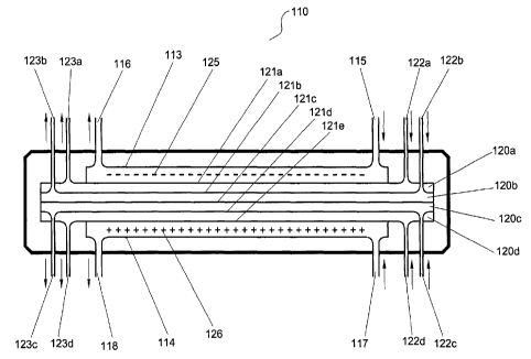
Figure 1 shows one embodiment of an electrophoresis separation unit
suitable for the apparatus according to the present invention having four
CA 02422325 2003-03-13
WO 02/28516 PCT/AU01/01256
14
separation chambers. The apparatus 110 comprises a cathode chamber 113 and
an anode chamber 114, each chamber having inlet 115, 117 and outlet 116, 118
means for feeding electrolyte into and out of the respective electrode
chambers
113, 114. Four separation chambers 120a, 120b, 120c, 120d, formed by five of
s ion-permeable barriers 121 a, 121 b, 121 c, 121 d, 121 a are positioned
between the
cathode and anode chambers 113, 114. Four inlet 122a, 122b, 122c, 122d and
four outlet 123a, 123b, 123c, 123d means for feeding liquid into and out of
the
respective separation chambers 120a, 120b, 120c, 120d are positioned near
each end of the unit 110.
1o The separation chambers 120a, 120b, 120c, 120d can be formed or
housed in a cartridge which is adapted to be removable from the unit 110.
Cathode and anode 125, 126 are housed in the anode and cathode chambers
113, 114 such that when an electric potential is applied between the
electrodes,
contents in the chambers are exposed to the electric potential.
~ 5 When electrolyte is passed into and out of the electrode chambers 113,
114 via inlets 115, 117 and outlets 116, 118 fluid streams are formed in the
respective chambers. Similarly, when fluid is passed into and out of the
separation chambers 120a, 120c, 120c, 120d via inlets 122a, 122b, 122c, 122d
and outlets 123a, 123b, 123c, 123d fluid streams are formed in the respective
2o chambers.
Figure 2 shows another embodiment of a separation unit suitable for the
apparatus according to the present invention having six separation chambers.
The apparatus 210 comprises a cathode chamber 213 and an anode chamber
214, each chamber having inlet 215, 217 and outlet 216, 218 means for feeding
2s electrolyte into and out of the respective electrode chambers 213, 214.
Positioned between the electrode chambers 213, 214 are six separation
chambers 220a, 220b, 220c, 220d, 220e, 220f formed by seven ion-permeable
barriers 221 a - 121 g positioned between the cathode and anode chambers 213,
214 forming the separation chambers 220a - 220f. Six inlet 222a, 222b, 222c,
30 222d, 222e, 222f and six outlet 223a, 223b, 223c, 223d, 223e, 223f means
for
feeding liquid into and out of the respective separation chambers 220a - 220f
are
positioned near each end of the unit 210.
CA 02422325 2003-03-13
WO 02/28516 PCT/AU01/01256
The separation chambers 220a - 220f can be formed or housed in a
cartridge which is adapted to be removable from the unit 210. Cathode and
anode 225, 226 are housed in the anode and cathode chambers 213, 214 such
that when an electric potential is applied between the electrodes 225, 226
5 ~ contents. in the separation chambers 220a - 220f are exposed to the
potential.
The apparatus depicted in Figure 2 has the inlet and outlet means of each
separation chamber 220a - 220f separated fluidly from each other. In contrast,
Figure 3 depicts an apparatus 310 with six separation chambers 320a, 320b,
320c, 320d, 320e, 320f of which three chambers 320a, 320c, 320e are in fluid
1o connection by common inlet 322a and common outlet 323a means. The other
three separation chambers 320b, 320d, 320f are in fluid connection by common
inlet 322b and common outlet 323b means. When fluid is passed into inlet
means 322a and out of outlet means 323a, fluid passes through separation
chambers 320a, 320c, 320e forming a separation stream in the chambers.
15 Similarly, when fluid is passed into inlet means 322b and 'out of outlet
means
323b, fluid passes through separation chambers 320b, 320c, 320f forming a
separation stream in those chambers.
Figure 4 shows another embodiment of the apparatus according to the
present invention having twelve separation chambers. The apparatus 410.
2o comprises a cathode chamber 413 and an anode chamber 414, each chamber
having inlet 415, 417 and outlet 416, 418 means for feeding electrolyte into
and
out of the electrode chambers 413, 414. Twelve separation chambers 420a -
4201 are positioned between the cathode and anode chambers 413, 414. The
separation chambers 420a -4201 are formed by thirteen ion-permeable barriers
421 a - 421 m positioned between the cathode and anode chambers 413, 414.
Twelve inlet 422a - 4221 and twelve outlet 423a - 4231 means are positioned
relative to each end of the unit 410 for feeding liquid into and out of the
respective
twelve separation chambers 420a - 4201.
The separation chambers 420a - 4201 can be formed or housed in a
so cartridge which is adapted to be removable from the apparatus 410. Cathode
and anode 425, 426 are housed in the anode and cathode chambers 413, 414.
The apparatus depicted in Figure 4 has each separation chamber 420a -
4201 separated fluidly from each other. It will be appreciated, however, that
one
CA 02422325 2003-03-13
WO 02/28516 PCT/AU01/01256
16
or more chambers can share the same inlet and outlet means so that the same
material may be passed through more than one separation chamber if required.
Figure 5A shows an exploded view of a separation unit adapted to house
thirteen ion-permeable barriers forming twelve separation chambers. The unit
~ 510 includes a cathodic connection block 530 which defines six inlet 522a -
522f
and outlet 523a - 523f means for feeding liquid into and out of six upper
separation chambers and housing cathode 525. An anodic connection block 531
defines six lower inlet 522g - 5221 and outlet 523g - 5231 means for feeding
liquid
into and out of six lower separation chambers and housing anode 526 in the
a~nodic connection block 531. The unit 510 has catholyte inlet 515 and outlet
516
means in the cathodic connection block 530 to pass electrolyte through the
block
530 which houses a cathode. Similarly, the anodic block 531 has anolyte inlet
517 and outlet 518 means for passing electrolyte through the anodic block
which
houses an anode.
~5 The cathodic and anodic connection blocks 530, 531 house electrodes
525, 526 and connection means 527, 528 for connecting the electrodes to a
power supply. The electrodes 525, 526 are usually made of titanium mesh
coated with platinum, but other inert electrically-conducting materials would
also
be suitable. The anode 526 is attached to the anode block 531 by suitable
2o attaching means such as screws 533. Similarly, the cathode is attached to
the
cathode block by suitable attaching means such as screws 534.
The anode connection block 531 contains recess 532 for receiving ion-
permeable membranes and cathode housing block 530. Barriers are layered
into the recess 532 forming a cathode chamber and the.required number of
25 sample chambers. When the cathode block is placed in the recess containing
the
barriers, the cathode chamber is also formed.
Figure 5B shows the separation unit 510 partially assembled in a U-shaped
housing 511. The cathode block 530 is placed in housing 511 and a threaded
bolt 512 passes through the housing and threaded into a plate 514 positioned
on
so the top of the cathode block 530. Attachment means 513 is provided for the
anode block 531 to ensure the unit 510 is correctly positioned in the housing
511.
CA 02422325 2003-03-13
WO 02/28516 PCT/AU01/01256
17
Figure 5C shows the separation unit 510 fully assembled in the housing
511. The threaded bolt 512 is tightened forcing the cathode block ,into the
anode
block sandwiching the barriers.
Figures 6A, 6B and 6C show preferred grid elements 601 a, 601 b, 601 c
s , respectively which, when assembled in the separation unit or a cartridge
adapted
to be placed in a separation unit according to the present invention, assist
in
supporting the ion-permeable barriers which form the electrode and separation
chambers.
Figure 6A shows a plan view of a preferred grid element 601a which is
incorporated as a component of separation unit 10. An elongate rectangular cut-
out portion 602 which incorporates lattice 603 is defined in, the center of
the grid
element 601 a. At each end of the grid element 601 a, there is positioned six
ports
604, 605, 606, 607, 608, 609 suitably provided for alignment with other
components of separation unit 10. Preferably, at one port at each end there is
a
15 triangular channel area 641 having sides and a base, which extends and
diverges
from the associated port 604 to cut-out portion 602. Upstanding ribs 642, 643
and 644 are defined in channel area 641. Liquid flowing through port 604 thus
passes along triangular channel area 641 between ribs 642, 643 and 644 and
into lattice 603. Ribs 642, 643 and 644 direct the flow of liquid from port
604 so
2o that they help ensure that liquid is evenly distributed along the cross-
section of
lattice 603: Ribs 642, 643 and 644 also provide support to an ion-permeable
barrier disposed above or below the grid element.
Lattice 603 comprises a first array of spaced parallel members 645
extending at an angle to the longitudinal axis of the grid disposed above and
2s integrally formed with a. second lower set of spaced parallel members 646
extending at approximately twice the angle of the first array of parallel
members
645 to the longitudinal axis of the grid. In the presently preferred
embodiment,
the first array of parallel members 645 extend at approximately a 45 degree
angle
from the longitudinal axis and the second array of parallel members 646 extend
at
3o approximately 90 degrees to the first array of parallel members 645,
however,
other angles are also suitably used.
The other ports, 605, 606, 607, 608, 609 do not have the rib configuration
as in port 604 in grid 601 a but are positioned to also allow flow of fluid to
a
CA 02422325 2003-03-13
WO 02/28516 PCT/AU01/01256
18
separation chamber 20 other than the chamber that port 604 is in fluid
communication. A second grid 601 b is shown in Figure 6B where the equivalent
port 605 of grid 601a contains the rib arrangement 642, 643 and 644 for
assisting
the flow of fluid into the chamber that is in fluid communication with grid
601 b.
s Similarly, Figure 6C shows a third grid 601 c where the equivalent port 606
of grid
601 a contains the rib arrangement 642, 643 and 644 for assisting the flow of
fluid
into the chamber that is in fluid communication with grid 601c. Depending on
the
number of grids and ion-permeable barriers used and the orientation of the
grids
assembled in a unit, a plurality of separation chambers can be formed which
can
be isolated fluidly from each other or may be in fluid communication with
tv~ro or
more separation chambers.
The thickness of the grid element is preferably relatively small. In one
presently preferred embodiment, exterior areas of the grid element are 0.8 mm~
thick. A sealing rib or ridge can extend around the periphery of lattice 603
to
15 improve sealing on the reverse side of the grid element. The ridge is
preferably.
approximately 1.2 mm thick measured from one side of the grid element to the
other. The distance between the opposite peaks of lattice elements 645 and 646
measured from one side of the grid to the other is preferably approximately 1
mm.
The relatively small thickness of the grid provides several advantages. First,
it
20 results in a more even distribution of liquid over ion-permeable barrier 21
and
assists in inhibiting its fouling by macromolecules or other viscous
compounds.
Also, the volume of liquid required is decreased by the use of a relatively
thin grid which enables relatively small sample volumes to be used for
laboratory-
scale separations, a significant advantage over prior art separation devices.
2s Finally, if the electric field strength is maintained constant, the use of
a
relatively thinner grid element enables less electrical power to be deposited
into
the liquid. If less heat is transferred into the liquid, the temperature of
the liquid
remains lower. This is advantageous since high temperatures may destroy both
the sample and the desired product.
3o The separation unit can house a cartridge or cassette and includes an
anodic connection block and a cathodic connection block between which, in use,
the cartridge is clamped.
CA 02422325 2003-03-13
WO 02/28516 PCT/AU01/01256
19
The cartridge comprises a cartridge housing which holds the components
of the cartridge such as grid elements 601 and ion-permeable barriers 21. The
cartridge is generally elongate and includes two parallel elongate side walls
which
extend along the longitudinal axis A-A of the cartridge. Each end of the
cartridge
s includes end walls so that the cartridge is generally oval in plan view. A
small
flange extends around the base of the walls. The flange projects inwards
towards
the centre of the cartridge. Optionally, planar silicon rubber gaskets whose
exterior is generally oval are configured to fit inside the walls of the
cartridge
resting on the flange to assist in sealing the components. If used, the centre
of
1o the gasket defines an elongate cut out portion. Adjacent to either end of
the seal
there are a number of holes, depending on the number of separation chambers
provided in the cartridge.
Above the gasket is located an ion-permeable barrier whose external
shape is generally the same as that of the interior of the cartridge, so that
it too
15 fits inside the cartridge. Each barrier has several holes adjacent to
either end of
the membrane and positioned so that when the cartridge is assembled, those
holes align with the holes of the gasket.
Above the first barrier there is a grid element. Above that grid element is a
second barrier. More grid elements are stacked with corresponding barriers
2o positioned in between to provide the number of separation chambers
required.
Examples of stacking arrangement of grid elements and ion-permeable
barriers are shown in Figures 7 to 10. Figure 7 shows exploded view of an
arrangement forming three separation chambers. The unit contains four barriers
721 a - 721 d and three grid elements 701 c, 701 b, 701 a. Barrier 721 a is
2s positioned at the cathode side of the separation unit and is supported by
grid
element 701 c. A first separation chamber is formed between barrier 721 a and
element 701 c. A second barrier 721 b is positioned between grid elements 701
c
and 701 b such that a second sample chamber is formed between barrier 721 b
and grid element 701 b. Third barrier 721 c is positioned between the grid
3o elements 701b and 701a forming a third sample chamber between the third
barrier 721 c and grid element 701 a. Fourth barrier 721 d is positioned at
the
anode side of the separation unit.
CA 02422325 2003-03-13
WO 02/28516 PCT/AU01/01256
In a similar arrangement, Figure 8 shows an exploded view of an
arrangement of barriers and grid elements forming four separation chambers.
The unit contains five barriers 821 a - 821 a and four grid elements 801 c,
801 b,
801a. Figure 9 shows an exploded view of an arrangement of barriers and grid
s elements forming six separation chambers. The unit contains seven barriers
921 a - 921 g and six grid elements 901 a, 901 b, 901, 901 d, 901 e, 901 f.
Figure 10
shows an exploded view of an arrangement of barriers and grid elements forming
twelve separation chambers. The unit contains thirteen barriers 1021 a - 1021
m
and twelve g rid elements 1001 a, 1001 b~ 1001 c, 1001 d, 1001 e, 1001 f. It
will be
appreciated from the examples provided that the modular approach of the
present invention using barriers and grid elements allows the preparation of
many
different arrangements.
One function of the grid element is to keep the barriers apart. The grid
element also has to provide a path for the sample or electrolyte flow in each
15 separation chamber since the grid elements for each chamber are similar.
The
grid element is generally planar and the exterior of the grid element is
shaped to
fit inside the walls of the cartridge housing.
The ion-permeable barrier is selected depending on the application.
Following each separation barrier there are preferably further elements:-
there is
2o a further grid element, a ion-permeable barrier, and a further gasket
symmetrically arranged about the barrier. Those stacked components form the
separation chamber and a part of the boundary of the electrode chamber stream.
The components are held in the cartridge by means of a clip or screw or some
other suitable fastener.
The main function of the cartridge is to hold the components together for
insertion into the separation unit. The actual cartridge walls may have no
effect
on the sealing of the apparatus. If the apparatus is correctly sealed, no
liquid
should contact the walls of the cartridge in use.
The cathode and anode can be formed from platinum coated titanium
3o expanded mesh, in contrast with the standard electrodes usually used for
electrolytic cells which comprise platinum wire. The platinum coated titanium
expanded mesh used in the apparatus of the present invention has several
advantages over platinum wire. In particular, the ridged structure is self
CA 02422325 2003-03-13
WO 02/28516 PCT/AU01/01256
21
supporting and less expensive than platinum wire. The mesh also provides a
greater surface area and allows lower current densities on the electrode
surfaces.
Also, the larger surface area distributed over the electrolyte channel
provides a
more even electrical field for the separation process.
The electrodes are also located close to the adjacent ion-permeable
barriers. Therefore, less of the applied potential drops across the layers of
the
anolyte and the catholyte, and less heating of the liquid occurs. Connectors
from
the electrodes pass to sockets for connection of electrical power to the
electrodes. The electrodes are shrouded to prevent accidental contact with an
operator's fingers or the like.
In use, the cartridge is loaded into the unit, or alternatively the barriers
and
- grid elements assembled in the unit, jaws forming a locking arrangement are
closed to seal 'the components in place, the electrolyte solutions and samples
are
fed through the connection blocks via the appropriate inlet and outlet means.
The
~5 unit is connected to an electrophoresis apparatus which includes pumps,
plumbing and cooling provisions, if required. Connection is also made to a
power
supply in order to provide the electric potential for a given separation. The
electric potential is set to the desired value and separation carried out as
required. After the separation has been carried out, the cartridge may be
reused,
20 removed or replaced with a fresh cartridge. Alternatively, the barriers and
grid
elements can be reused or disassembled from the unit. Tubing connecting the
.inlet and outlet means may be cleaned and the electrolyte replaced, if
necessary.
Following that, the unit is ready to carry out a further separation.
The electrolyte solution provides the required conductivity, may also
25 stabilise the pH during separation and act as the cooling medium.
The design of the separation unit is easily adaptable for a multi-channel
separation unit and apparatus with up to twelve chambers. More separation
chambers can be accommodated increasing the complexity of the arrangement
regarding plumbing and pumping fluid to the chambers. For excellent
flexibility,
3o the present inventors developed a new grid design which could be expanded
to
accommodate a variable number of extra separation chambers. In one form, the
new design allows up to twelve separation chambers (plus, the two electrode
chambers) having six similar but distinct grids having six holes in each end.
CA 02422325 2003-03-13
WO 02/28516 PCT/AU01/01256
22
Twelve sample chambers are formed by stacking two sets of six grids placed
into
an apparatus having up to twelve different sets of fluid connections. In one
form,
there are three similar but distinct grids with three holes in each end to
enable
three different sets of connections. The grids can be stacked to form six
separation chambers. The design allows the convenient formation of up to
twelve
separation chambers.
A schematic diagram of an electrophoresis apparatus 2 utilizing a
separation unit 110 of Figure 1 is shown in Figure 11 for the purpose of
illustrating the general functionality of an apparatus utilizing the
technology of the
present invention. In this purely illustrative example, six chambers (cathodic
chamber 113, anodic chamber 114, and four separation chambers 120a-120d)
are connected to six flow circuits. First electrolyte flow circuit 40
comprises first
electrolyte reservoir 42, electrolyte tubing 44, and electrolyte pump 46.
'Second
electrolyte flow circuit 41 comprises second electrolyte reservoir 43,
electrolyte
~5 tubing 45, and electrolyte pump 47. In the configuration shown in Figure
11,
electrolyte flow circuits 40 and 41 are running independently from each other
so
that the composition, temperature, flow rate and volume of first electrolyte
36 and
second electrolyte 38 can be suitably adjusted independently of one another.
In the embodiment shown, first electrolyte 36 flows from first electrolyte
2o reservoir 42 through tubing 44 to pump 46 to first electrolyte chamber 113.
Second electrolyte 38 flows from second electrolyte reservoir 43 through
tubing
45 to pump 47 to second electrolyte chamber 114. First electrolyte 36 flows
through inlet 115 and second electrolyte 38 flows through inlet 117. First
electrolyte 36 exits separation unit 110 through outlet 116 and second
electrolyte
25 38 exits separation unit 110 through outlet 118. After exiting separation
unit 110,
electrolytes 36 and 38 flow through tubing 44 and 45 back into respective
electrolyte reservoirs 42 and 43. In one embodiment, electrolytes 36 and 38
are
held stagnant in electrolyte chambers 113 and 114 during separation.
Electrolytes 36 and 38 can also act as a cooling medium and help prevent a
build
3o up of gases generated during electrophoresis.
First separation flow circuit 58 contains first sample reservoir 50a, tubing
52 and pump 54. First sample 56 flows from first sample reservoir 50a through
CA 02422325 2003-03-13
WO 02/28516 PCT/AU01/01256
23
tubing 52 to pump 54, then through inlet 122a into first separation chamber
120a.
In one embodiment, the flow directions of first sample 56 and electrolytes 36
and
38 in first sample chamber 120a are opposite. First sample 56 exits separation
unit 110 at outlet 123a and flows through tubing 52, then heat exchanger 70
s wbefore returning to first sample reservoir 50a through tubing 52. In an
alternative
embodiment, heat exchanger 70 passes through first electrolyte reservoir 42.
In
another embodiment, the flow directions of first sample 56 and electrolytes 36
and 38 in first sample chamber 120a are the same.
In addition to components of interest, first sample 56 may contain any
suitable electrolyte or additive known in the art as demanded by the
procedure,
application, or separation being performed to substantially prevent or cause
migration of selected components through the ion-permeable barriers. In a
preferred embodiment, sample from which constituents are removed is placed
into first sample reservoir 50a. However, it is understood that in an
alternative
embodiment, sample from which constituents are removed is placed into second
sample reservoir 50b.
Similarly, second sample flow circuit 68 contains second sample reservoir
50b, tubing 62 and pump 64. Second sample 66 flows from second sample
reservoir 50b through tubing .62 to pump 64, then through inlet 122b into
second
2o sample chamber 120b. In one embodiment, the flow directions of second
sample
66 and electrolytes 36 and 38 in second sample chamber 120b are opposite.
Second sample 66 exits separation unit 110 at outlet 123b and flows through
tubing 62, to heat exchanger 70 before returning to second sample reservoir
50b
through tubing 62. In an alternative embodiment, heat exchanger 70 passes
25 through first electrolyte reservoir 42 or second electrolyte reservoir 43.
Second sample 66 may contain any suitable electrolyte or additive known
in the art as demanded by the procedure, application, or separation being
performed to substantially prevent or cause migration of selected components
through the ion-permeable barriers. In a preferred embodiment, sample from
3o which constituents are removed is placed into second sample reservoir 50b.
However, it is understood that in an alternative embodiment, sample from which
constituents are removed is placed into first sample reservoir 50a.
CA 02422325 2003-03-13
WO 02/28516 PCT/AU01/01256
24
Similarly, third sample flow circuit 78 contains third sample reservoir 50c,
tubing 72 and pump 74. Third sample 76 flows from third sample reservoir 50c
through tubing 72 to pump 74, then through inlet 122c into third sample
chamber
120c. In one embodiment, the flow directions of third sample 76 and
electrolytes
s 36 and 38 in third sample chamber 120c are opposite. Third sample 76 exits
separation unit 110 at outlet 123c and flows through tubing 72, to heat
exchanger
70 before returning to third sample reservoir 50c through tubing 72. In an
alternative embodiment, heat exchanger 70 passes through first electrolyte
reservoir 42 or second electrolyte reservoir 43.
Third sample 76 may contain any suitable electrolyte or additive known in
the art as demanded by the procedure, application, or separation being
performed to substantially prevent or cause migration of selected components
through the ion-permeable barriers. In a preferred embodiment, sample from
which constituents are removed is placed into third sample reservoir 50c.
15 However, it is understood that in an alternative embodiment, sample from
which
constituents are removed is placed into first sample reservoir 50a, or second
sample reservoir 50b.
Similarly, fourth sample flow circuit 88 contains second sample reservoir
50d, tubing 82 and pump 84. Fourth sample 86 flows from. fourth sample
2o reservoir 50d through tubing 82 to pump 84, then through inlet 122d into
fourth
sample chamber 120d. In one embodiment, the flow directions of fourth sample
86 and electrolytes 36 and 38 in second sample chamber 120d are opposite.
Fourth sample 86 exits separation unit 110 at outlet 123d and flows through
tubing 82, to heat exchanger 70 before returning to fourth sample reservoir
50d
2s through tubing 82. In an alternative embodiment, heat exchanger 70 passes
through first electrolyte reservoir 42 or second electrolyte reservoir 43.
Fourth sample 86 may contain any suitable electrolyte or additive known in
the art as demanded by the procedure, application, or separation being
performed to substantially prevent or cause migration of selected components
3o through the ion-permeable barriers. In a preferred embodiment, sample from
which constituents are removed is placed into third sample reservoir 50c.
However, it is understood that in an alternative embodiment, sample from which
CA 02422325 2003-03-13
WO 02/28516 PCT/AU01/01256
constituents are removed is placed into first sample reservoir 50a or the
second
sample reservoir 50b.
The heat exchanger 70 is preferably a tube-in-shell apparatus having
pump 94 which passes cooled fluid via tubing 92 from reservoir 93 through the
5 exchanger 70. As fluid is passed through the heat exchanger 70 in its
respective
tubing, the contents is suitably cooled to the desired temperature.
Individually adjustable flow rates of first sample 56, second sample 66,
third sample 76, fourth sample 86, first electrolyte 42 and second electrolyte
43,
when employed, can have a significant influence on the separation. Flow rates
ranging from zero through several milliliters per minute to several liters per
minute
are suitable depending on the configuration of the apparatus and the
composition, amount and volume of sample processed. In a laboratory scale
instrument, individually adjustable flow rates ranging from about 0 mL/minute
to
about 50,000 mUminute are used, with the preferred flow rates in the 0 mUmin
to
15 about 1,000 mL/minute range. However, higher flow rates are also possible,
depending on the pumping means and size of the apparatus. Selection of the
individually adjustable flow rates is dependent on the process, the component
or
components to be transferred, efficiency of transfer, and coupling of the
process
with other, preceding or following processes.
2o Furthermore, it is preferable that sample flow circuits 58, 68, 78, and 88,
first electrolyte flow circuit 40 and second electrolyte flow circuit 41 are
completely enclosed to prevent contamination or cross-contamination. In a
preferred embodiment, reservoirs 50a - 50d, 42, and 43 are completely and
individually enclosed from the rest of the apparatus.
25 The separation unit 110 further comprises electrodes 125 and 126.
Preferably, the respective electrodes are located in the first and second
electrolyte chambers 113, 114 and are separated from the first and second
sample chambers by ion-permeable barriers.
Electrodes 125 and 126 are suitably standard electrodes or preferably are
so formed from platinum coated titanium expanded mesh, providing favorable
mechanical properties, even distribution of the electric field, long service
life and
cost efficiency. Electrodes 125 and 126 are preferably located relatively
close to
CA 02422325 2003-03-13
WO 02/28516 PCT/AU01/01256
26
ion-permeable barriers 121a and 121e providing better utilization of the
applied
potential and diminished heat generation. A distance of about 0.1 to 6 mm has
been found to be suitable for a laboratory scale apparatus. For scaled-up
versions, the distance will depend on the number and type of ion-permeable
s barriers, and the size and volume of the electrolyte and sample chambers.
Preferred distances would be in the order of about 0.1 mm to about 10 mm.
Separation unit 110 also preferably comprises electrode connectors 79
that are used for connecting separation unit 110 to power supply 73.
Preferably,
power supply 73 is external to separation unit, however, separation unit 110
is
configurable to accept internal power supply 73.
Separation is achieved when an electric potential is applied to separation
unit 110. Selection of the electric field strength (potential) varies
depending on
the separation. Typically, the electric field strength varies between 1 V/cm
to
about 5,000 V/cm, preferably between 10 V/cm to 2,000 V/cm. It is preferable
to
15 maintain the total power consumption in the unit at the minimum,
commensurable
with the desired separation and production rate.
In one embodiment, the applied electric potential is periodically stopped
and reversed to cause movement'of components that have entered the ion-
permeable barriers back info at least one of the fluid streams, while
substantially
2o not causing re-entry of any components that have entered other fluid
streams. In
another embodiment, a resting period is utilized. Resting (a period during
which
fluid flows are maintained but no electric potential is applied) is an
optional step
that suitably replaces or is included after an optional reversal of the
electric
potential. Resting is often used for protein-containing samples as an
alternative
25 to reversing the potential.
Separation unit 110 is suitably cooled by various methods known in the art
such as ice bricks or cooling coils (external apparatus) placed in one or both
electrolyte reservoirs 42 and 43, or any other suitable means capable of
controlling the temperature of electrolytes 36 and 38. Because both sample
flow
so circuits 58, 68, 78 and 88 pass through heat exchanger 70, heat is
exchanged
between samples and one or both of first and second electrolytes. Heat
exchange tends to maintain the temperature in the samples at the preferred,
CA 02422325 2003-03-13
WO 02/28516 PCT/AU01/01256
27
usually low levels.
The present invention further encompasses electrophoresis apparatus
utilising separation units having from three to at least twelve separation
chambers
as described above. For example, the separation units described with reference
to Figures 2 to 4 can also be used with the appropriate number of flow paths,
pumps, and sample chambers.
Figure 12 shows a schematic of an electrophoresis apparatus 2 having two
electrolyte flow paths 3, twelve separation flow paths 6, sample and
electrolyte
reservoirs 5 and a cooling facility 7. Separation unit 10 houses twelve
separation
chambers, cathode chamber and anode chamber. Pumps 4 communicate fluid to
the separation unit 10 from the sample and electrolyte chambers 5.
An advantage of the present invention is the ability to arrange for a
separation apparatus having three or more separation chambers in various
configurations.
In one embodiment, an ion-permeable barrier is formed from a membrane
with a characteristic average pore size and pore-size distribution. The
average
pore size and pore size distribution of the membrane is selected to facilitate
trans-membrane transport of certain constituents, while substantially
preventing
traps-membrane transport of other constituents.
2o In another embodiment, an ion-permeable barrier is an isoelectric ion-
permeable barrier, such as an isoelectric membrane that substantially prevents
connective mixing of the contents of adjoining chambers, while permits
selective
traps-barrier transport of selected constituents upon application of the
electric
potential. Suitable isoelectric membranes can be produced by copolymerizing
2s - acrylamide, N,N'-methylene bisacrylamide and appropriate acrylamido
derivatives
of weak electrolytes yielding isoelectric membranes with p1 values in the 2 to
12
range, and average pore sizes that either facilitate or substantially prevent
trans-
membrane transport of components of selected sizes.
In another embodiment, an ion-permeable barrier is an ion-exchange ion-
3o permeable barrier, such as anion-exchange membrane that substantially
prevents connective mixing of the contents of adjoining chambers, while
permits
selective traps-barrier transport of selected constituents upon application of
the
electric potential. Suitable ion-exchange membranes are strong-electrolyte and
CA 02422325 2003-03-13
WO 02/28516 PCT/AU01/01256
28
weak-electrolyte functional-group containing porous membranes.
EXAMPLES
Example 1
s An apparatus according to the present invention containing twelve
separation chambers was used to separate immunoglobulin G (IgG) from human
plasma. This example demonstrated the use of the apparatus for processing the
same feed sample, from the same sai~nple reservoir, through four sets of
identical, multiple, parallel separation chambers.
The separation unit was assembled as follows. All ion-permeable barriers
were polyacrylamide membranes with different nominal molecular mass cut-offs
(NMM). The first set of parallel separation chambers started with a 1St ion-
permeable barrier between the anode compartment and the first separation
chamber with an NMM of 5,000 dalton, through the next barrier between the 1St
15 and 2"d separation chambers with an NMM of 100,000 dalton, then the next
barrier between the 2"d and 3rd separation chambers with an NMM of greater
than
1,000,000 dalton. The second set of parallel separation chambers started with
the barrier between the 3~d and 4t" separation chambers with an NMM of 5,000
dalton, through the next barrier between the 4t" and 5t" separation chambers
with
2o an NMM of 100,000 dalton, then the next barrier between the 5th and gtn
separation chambers with an NMM of greater han 1,000,000 dalton. The third
set of parallel separation chambers started with the barrier between the 6~"
and
7tn separation chambers with an NMM of 5,000 dalton, through the next barrier
kietween the 7tn and 8t" separation chambers with an NMM of 100,000 dalton,
2s then the next barrier between the 8t" and 9t" separation chambers with a
NMM of
greater than 1,000,000 dalton. Finally, the fourth set of parallel separation
chambers started with the barrier between the 9t" and 10t" separation chambers
with an NMM of 5,000 dalton, through the next barrier between the 10t" and
11t"
separation chambers with an NMM of 100,000 dalton, then the next barrier
3o between the 11th and 12t" separation chambers with an NMM of greater than
1,000,000 dalton. The 12t" separation chamber is separated from the cathode
compartment by an ion-permeable barrier with an NMM of 5,000 dalton.
CA 02422325 2003-03-13
WO 02/28516 PCT/AU01/01256
29
The electrolyte in the anode and cathode compartments (2 L each), as well.
as in the 1St, 2nd, 4tn, Stn, 7tn, Stn, and 10th, 11th separation chambers (20
mL each)
was identical: 60 mM MOPS and 40 mM GABA at pH 5.50. The feed sample was
prepared by diluting human plasma at a rate of 1 to 10 with the same pH 5.50,
60
s mM MOPS and 40 mM GABA buffer (final pH 6.02). One hundred and ten mL of
this sample was loaded into the 3'd, 6tn, Stn and 12tn separation chambers.
The separation was conducted at 600V for 180 min. The current was
around 34 mA during the separation. At pH 5.5, IgG was cationic and moved
toward the cathode, crossed the greater than 1,000,000 dalton NMM barriers,
but
could not cross the 100,000 dalton NMM barriers, and thus was trapped in
separation chambers 2, 5, 8, and 11 as the product. The low molecular mass
proteins proceeded through the NMM 100,000 barrier and were trapped in
streams 1, 4, 7 and 10 (contaminant stream). Transfer of IgG from the sample
stream to the product stream was evident at the first analysis point at 60
mins
~5 (Figure 13). The pH changes observed over the course of the separation are
listed in Table 1.
CA 02422325 2003-03-13
WO 02/28516 PCT/AU01/01256
Table 1. pH changes during purification of IgG from human plasma using a
multiple membrane stack and a single sample source.
Component initial final pH
pH
Catholyte 5.5 5.78
Contaminant stream5.5 5.47
Product stream 5.5 5.49
Feed stream 6.02 5.48
Anolyte 5.5 5.39
5 Example 2
An apparatus according to the present invention containing twelve
separation chambers was used to separate IgG from human plasma. This
example demonstrated the use of the apparatus for processing the same feed
sample, from the same sample reservoir, through four sets of identical,
multiple,
parallel separation chambers using the principles of a pH-dependent charge-
based separation.
The separation unit was assembled as follows. All ion-permeable barriers
were polyacrylamide membranes with different nominal molecular mass cut-offs
(NMM). The first set of parallel separation chambers started with the 1St ion-
~5 permeable barrier between the anode compartment and the first separation
chamber with an NMM of 5,000 dalton, through the next barrier between the 1St
and 2nd separation chambers with an NMM of greater than 1,000,000 dalton. The
second set of parallel separation chambers started with the barrier between
the
2"d and 3~d separation chambers with an NMM of 5,000 dalton, through the next
2o barrier between the 3~d and 4t" separation chambers with an NMM of greater
than
1,000,000 dalton. The third set of parallel separation chambers started with
the
barrier between the 4t" and 5t" separation chambers with an NMM of 5,000
dalton, through the next barrier between the 5t" and 6t" separation chambers
with
an NMM of greater than 1,000,000 dalton. The fourth set of parallel separation
25 chambers started with the barrier between the 6t" and 7t" separation
chambers
CA 02422325 2003-03-13
WO 02/28516 PCT/AU01/01256
31
with an NMM of 5,000 dalton, through the next barrier between the 7t" and gtn
separation chambers with an NMM of greater than 1,000,000 dalton. The fifth
set
of parallel separation chambers started with the barrier between the Stn and
gtn
separation chambers with an NMM of 5,000 dalton, through the next barrier
s between the Stn and 10tn separation chambers with an NMM of greater than
1,000,000 dalton. The last, sixth set of parallel separation chambers starts
with
the barrier between the 10~n and 11tn separation chambers with an NMM of 5,000
dalton, through the next barrier between the 1ltn and 12th separation chambers
with an NMM of greater than 1,000,000 dalton. Finally, the 12tn separation
chamber was separated from the cathode compartment by an ion-permeable
barrier with an NMM of 5,000 dalton.
The electrolyte in the anode and cathode compartments (2 L each), as well
as in the lSc, ~rd~ 5tn, 7cn, Stn, and 11tn separation compartments (15 mL
each) was
identical: 60 mM MOPS and 40 mM GABA at pH 5.46. The feed sample was
15 prepared by diluting human plasma at a rate of 1 to 10 with the pH 5.46 60
mM
MOPS and 40 mM GABA buffer (final pH 6.0). Fifteen mL of this sample was
loaded into each of the 2~d, 4tn, gtn, Stn, l0tn, and 12tn separation
chambers.
The separation was conducted for 180 mins at 600V. The current was
around 30 mA during the separation. At pH 5.46, IgG was cationic and moved
2o toward the cathode, crossing the greater than 1,000,000 dalton NMM
barriers.
The higher p1 proteins were anionic and remained where they were fed: in
chambers 2"d, 4tn, gtn, Stn, l0tn, and 12tn, because even though they were
anionic,
they could not cross the NMM 5,000 barriers. At the end of the separation,
each
product and sample stream was collected, and 10 mL of phosphate-buffered
2s saline solution (PBS) was added to each stream and circulated for 10 min
without
applying the separation potential. The PBS solution was then collected from
each stream.
The transfer of IgG into the product streams was mostly complete at 60
mins (Figure 14). At the end of the separation, the pH of all sample streams
3o ranged from 5.49 to 5.55, the catholyte was pH 5.76 and the anolyte was pH
5.45.
CA 02422325 2003-03-13
WO 02/28516 PCT/AU01/01256
32
Example 3
An apparatus according to the present invention containing twelve
separation chambers was used to separate the components of chicken egg white
according to their size. This example demonstrated the use of the apparatus
for
s achieving size-based separations through the use of a series of ion-
permeable
barriers whose nominal molecular mass cut-off is different.
The separation unit was assembled as follows. All ion-permeable barriers
were polyacrylamide membranes with different nominal molecular mass cut-offs
(NMM). The ion-permeable barrier between the anode compartment and the 1 Sc
separation chamber was a polyacrylamide membrane with an NMM of 3,000
dalton. The barrier between the 1St and 2~d separation chambers had an NMM of
5,000 dalton, the barrier between the 2"d and 3~d separation chambers had an
NMM of 50,000 dalton, the barrier between the 3rd and 4t" separation chambers
had an NMM of 100,000 dalton, the next barrier between the 4t" and 5t"
~5 separation chambers had an NMM of 150,000 dalton, the next barrier between
the 5th and 6t" separation chambers had an NMM of 200,000 dalton. The barrier
between.the 6t" and 7t" separation chambers had an NMM of 300,000 dalton, the
next barrier between the 7t" and 8t" separation chambers had an NMM of 400,000
dalton. The 8t" and 9t" chambers were separated by an NMM 500,000 dalton
2o barrier. The 9t" and 1 Ot" separation chambers and the 10t" and 11 t"
separation
chambers were separated by 1,000,000 dalton NMM membranes. The barrier
between the 11t" and 12t" separation chambers had an NMM of 15,000 dalton.
The 12t" separation chamber was separated from the cathode compartment by
an ion-permeable barrier with an NMM of 3,000 dalton.
25 The electrolyte in the anode and cathode compartments (2 L each), as well
as in the 1St, 2nd, 3rd, 4c", 5cn, 6t"~ 7cn, 8c", 9c", 11t" and 12t"
separation
compartments (20 mL each) was identical: 90 mM Tris, 90 mM borate, 1 mM
EDTA at pH 8.51 (TBE). The feed sample was prepared by diluting 15 mL egg
white, at a rate of 1 to 4, with the electrolyte used in all the chambers and
filtered
3o through polyethylene terephthalate paper. Forty mL of this sample solution
was
loaded into the sample reservoir connected to separation chamber 10. The
separation was conducted at 600 V for 4 hours.
CA 02422325 2003-03-13
WO 02/28516 PCT/AU01/01256
33
Figure 15 shows the image of an SDS-PAGE separation of the contents of
the separation chambers after 4 hours of electrolysis. Lysozyme from egg white
(molecular mass 14 kDa, isoeiectric point of 10) moved into separation
chambers
11 and 12 (between the 3 kDa-15 kDa and 15 kDa-1000 kDa membranes),
because this protein is positively charged at pH 8.5 (Lanes 1 and 2).
Negatively
charged proteins moved toward the anode (Lanes 3-10): the smaller the size of
the protein, the farther away it moved from chamber 10 which was the feed
point
for the sample.
1 o Example 4
An apparatus according to the present invention containing twelve
separation channels was used to separate a-1-antitrypsin (AAT, 51 kDa, p1 =
4.8)
from human serum albumin (HSA, 66.5 kDa, p1 = 4.9). This example
demonstrated the use of the invented apparatus with Bier's buffers to carry
out
~5 quasi-isoelectric focusing separation of components with close p1 values in
a
shallow pH gradient generated from a binary mixture of weak electrolytes.
The separation unit was assembled as follows. All ion-permeable barriers
were polyacrylamide membranes with two different nominal molecular mass cut-
offs (NMM). The ion=permeable barriers between the anode chamber and the 1St
2o separation chamber, as well as between the 12t" separation chamber and the
cathode chamber had an NMM of 5,000 dalton. All other barriers between the 1St
and 2na, 2"a and 3~a, 3ra and 4t", 4t" and 5t", 5t" and 6t", 6t" and 7t", 7t"
and 8t", 8t"
and 9t", 9t" and 1 Ot", 1 Ot" and 11 t" and, finally, 11 t" and 12t"
separation chambers
had an NMM of 1,000,000 dalton.
25 The anolyte (2 L) contained 10 mM glycylglycine (gly-gly) and 90 mM
MES, at pH 4.01. The catholyte (2L) contained 90 mM gly-gly and 10 mM MES
at pH 5.14. All separation chambers contained mixtures (15 mL each) of gly-gly
and MES, at concentrations listed in Table 2 to set up the desired shallow pH
gradient. The feed sample was prepared by dissolving HSA at a level of 2 mg/mL
3o and AAT at a level of 0.5 mg/mL in 90 mM gly-gly and 10 mM MES buffer. The
total sample volume was 20 mL, its initial pH was 5.35. The sample was loaded
into separation chamber 12, next to the cathode. The sample was
CA 02422325 2003-03-13
WO 02/28516 PCT/AU01/01256
34
electrophoresed for 4 hours at 600 V. The current was about 40 mA during the
separation.
Figure 16 shows the image of an SDS-PAGE separation of the contents of
the separation chambers after 4 hours of electrolysis. Figure 17 shows the
image
of a Western blot of the same separation with an antibody against AAT.
HSA had accumulated in separation chambers 10 to 7 (Lanes 10 to 7 in
Figure 16), while AAT accumulated in separation chambers 7 to 4 (Lanes 7 to 4
in Figures 16 and 17). Pure AAT could be harvested from separation chambers 6
to 4 (Figure 17).
Table 2. pH gradient preparation and outcomes for the separation of HSA
from AAT.
Stream mM gly- mM MES start pH final protein
glY pH
10 (sample) 90 10 5.35 5.65 HSA
9 90 10 5.11 5.64 HSA
8 80 20 4.94 5.31 HSA
7 70 30 4.81 5.02 HSA/AAT
6 60 40 4.72 4.86 AAT
5 50 50 4.64 4.74 ~'T
4 40 60 4.55 4.53 ~'T
3 30 70 4.45 4.29 -
2 20 80 4.32 4.27 -
1 10 90 4.2 4.21
These examples indicate that remarkably good separation of components
can be achieved using the apparatus and method according to the present
CA 02422325 2003-03-13
WO 02/28516 PCT/AU01/01256
invention. The high production rates are attributed to the short
electrophoretic
migration distances, high electric field strength and good heat dissipation
characteristics of the system.
The invention has been described herein by way of example only. It will
5 be appreciated by persons skilled in the art that numerous variations and/or
modifications may be made to the invention as shown in the specific
embodiments without departing from the spirit or scope of the invention as
broadly described. The present embodiments are, therefore, to be considered in
all respects as illustrative and not restrictive. Other features and aspects
of this
invention will be appreciated by those skilled in ,the art upon reading and
comprehending this disclosure. Such features, aspects, and expected variations
and modifications of the reported results and examples are clearly within the
scope of the invention where the invention is limited solely by the scope of
the
following claims.