Note: Descriptions are shown in the official language in which they were submitted.
CA 02422398 2003-02-28
WO 01/18496 PCT/CA00/01026
-1-
GAS FLOW MEASURING APPARATUS AND SIGNAL PROCESSING
METHODS APPLICABLE THERETO
Field of the Invention
The present invention relates generally to gas flowmeters containing
one or more differential pressure transducers measuring pressure drop
across a flow-resistive element placed inside the gas passageway. More
particularly, the present invention relates to improvement in the accuracy of
flowmeters used in spirometry, by special design of the gas passageway,
by increasing its immunity to vibrations and by providing special signal
processing and a linearization method applicable to a flowmeter or other
like transducer signals.
Background
Typically, a gas flowmeter contains a gas flow receiver (GFR) (also
called gas passageway), a tube through which gas flow passes, and a
differential pressure transducer thus connected to the GFR. The transducer
measures differential pressure generated by a flow-resistive element
placed inside the tube. For certain applications, such as spirometry, GFRs
having simple shape, providing easy cleaning and/or disposability, are the
most attractive. Among GFRs used in industry and medicine, one can find
tubes with flow-resistive elements made in the form of plane diaphragms
(flow-obstacles designed to create local differential pressure while allowing
flow). The closest prototype used in spirometry, is the GFR with crest-like
flow-resistive element [US Patent 5038773].
The particular design of the GFR used in spirometry is the result of a
trade-off between the imperative to increase differential pressure generated
by the flow-resistive element to obtain higher sensitivity of the flowmeter,
and the requirement not to exceed a maximum acceptable back-pressure
specified by spirometry standards. For example, the American Thoracic
Society Standards for Spirometry (1994) require the back-pressure to be
CA 02422398 2003-02-28
WO 01/18496 PCT/CA00/01026
-2-
not greater than 150 Pa~s/I in the whole operating range. Therefore a GFR
with highest ratio (differential pressure)/(back pressure) is preferable for
this particular application.
Another problem to be solved in the described flowmeter is related
to reproducibility of the transformation characteristic of the GFR, which
defines flow-to-differential-pressure conversion. For this purpose, simpler
shapes of the GFR are easier to manufacture, with better reproducibility of
the dimensions of the inner features and surface of the tube, which
eventually guarantee reproducibility of the conversion. Another result of the
tube shape simplification is the reduction of manufacturing costs, which is
of great importance, especially for disposable tubes.
It has been shown [US Patent 5038773] that GFRs with flow-
resistive elements made in the form of plane diaphragms have essentially
non-linear flow-to-differential-pressure conversion characteristics.
Typically,
the differential pressure which is generated by this type of GFR is close to
a square function of the flow, which results in the following problem. A
requirement to measure flow in a dynamic range of 103, say from 15m1/s to
151/s (spirometry), necessitates the measurement of differential pressure,
generated by the GFR, in a dynamic range of 106=(103)2. On the other
hand, a limitation of maximal flow impedance of the GFR at about
150Pa-s/I, established by contemporary spirometry standards (American
Thoracic Society Standards for Spirometry), restricts the maximal
generated back-pressure to (150Pa~s/I)x(151/s)~2kPa. Therefore the
minimum detectable differential pressure of the pressure transducer should
be at the level of a few mPa. This requirement, combined with the
necessity to operate in a dynamic range of six orders of magnitude, is a
serious challenge for differential pressure transducers. Medical Graphics
Corp. proposed a flowmeter containing two differential pressure sensors
with an overlapping operating range of six orders of magnitude having a
special sensor activated at low flows [US Patent 5038773]. The electronic
CA 02422398 2003-02-28
WO 01/18496 PCT/CA00/01026
-3-
module of this spirometer has a sophisticated structure and contains sub-
modules providing analog signal conversion before being digitized by an
analog-to-digital converter (ADC).
Usage of thermoanemometer-type transducers connected in parallel
to the GFR for flow measurements has been reported earlier [U.Bonne,
K.Fritsch, "Mikroanemometer fur die Durchfluf~messung von Gasen,"
Technisches Messen, 1994, v.61, n.7, pp.285-294; T.R.Ohnstein,
R.G.Johnson, R.E.Higashi, D.W.Burns, J.O.Holmen, E.A.Satren,
G.M.Johnson, R.E.Bicking, S.D.Johnson, "Environmentally Rugged, Wide
Dynamic Range Microstructure Airflow Sensor," Proceedings on Solid-
State Sensors and Actuators Conference (1990), pp.158-160]. One
particular thermoanemometer-type transducer has a linear operating range
of about four orders of magnitude and total operating range of more then
six orders of magnitude [Frolov G.A., Gendin A.V., Grudin O.M., Katsan I.I.,
Krivoblotskiy S.N., Lupina B.I, "Micromechanical thermal sensors for gas
parameters measurements," Proceedings of 1996 ASME International
Engineering Congress and Exposition, DSC-Vo1.59, Micro-electro-
mechanical systems, pp. 61-65]. This particular transducer covers the
whole operating range that makes it attractive for usage in flowmeters.
Another advantage of thermoanemometer-type sensors is that their
resolution can be improved to a level as fine as several mPa without
degrading their dynamic properties. For example, the response time of the
mass flow AWM-series sensors manufactured by Honeywell Inc., with
resolution mentioned above, is about 3ms.
A thermoanemometer-type transducer contains a functional element
sensitive to gas flow passing through a specially designed gas flow
assembly [US Patent 4548078]. This gas flow is proportional to pressure
drop across the transducer, which makes it also possible to use it also for
differential pressure measurements. The physical principle of gas flow
measurement is based on flow-induced disturbance of a symmetrical
temperature distribution in the gas around a heater. This disturbance,
CA 02422398 2003-02-28
WO 01/18496 PCT/CA00/01026
-4-
caused by the shift of the heated volume of gas in the direction of flow, is
usually detected by a pair of temperature-sensitive elements. Typically, the
flow-sensitive element contains one or two heaters, which warm the gas in
a certain region of the flow channel. It also includes at least two
temperature-sensitive elements detecting distortion of the temperature
distribution in the heated volume of gas. The functions of gas heating and
temperature sensing can be separated, for example, as in the sensor with
the central heater and two temperature-sensing elements on opposite sides
of the heater [US Patent 4548078]. In an other design, the flow sensor may
use only two self-heated temperature-sensing elements, which warm the
gas and measure the temperature difference simultaneously [H-E. de Bree,
P. Leussink, T. Korthorst, H. Jansen, T S J. Lammerink, M. Elwenspoek,
"The p-flown: A novel device for measuring acoustic flows," Sensors and
Actuators A (1996), v.54, n.1, pp.552-557]. The differences between such
designs are not sufficient for subsequent consideration in this document.
Thermoanemometer-type flow or differential pressure transducers
are sensitive to acceleration acting in the direction parallel to the gas flow
in
the transducer flow channel. This effect, caused by the shift of the heated
volume of gas having lower density than the surrounding colder gas, results
in a temperature difference sensed by the two temperature-sensitive
elements. Acceleration applied in directions perpendicular to the gas flow
also causes shift of the heated volume of gas, but this shift is in a
direction
which does not significantly change the temperature difference measured
at the two temperature-sensitive elements. Therefore the transducer has
low sensitivity to acceleration perpendicular to gas flow. In general, in a
single sensor, the acceleration-induced output signal is indistinguishable
from a flow-induced signal. Sensitivity to acceleration of the considered
differential pressure transducers adversely affects the accuracy of the
transducers and hence the gas flowmeter exposed to mechanical
disturbances such as vibrations, rotation and displacement.
CA 02422398 2003-02-28
WO 01/18496 PCT/CA00/01026
-5-
Another problem is also caused by the necessity to detect and
process differential pressure signals approximately 1000 times lower than
those generated by near-linear GFRs (for example, Fleisch- or Lilly-type
tubes in spirometry). During flowmeter operation (for example, spirometry
testing), some vibrations or shocks of the device parts, such as the
pneumatic hoses connecting the GFR with differential pressure sensor,
may occur. Being negligibly small with respect to differential pressure
signals generated by linear GFRs, these parasitic signals may nevertheless
be significant compared to useful signals generated by nonlinear GFRs.
Interference by spurious signals such as these, reduces the accuracy of the
flowmeter. Immunity to these vibrations is considered to be an important
feature of the flowmeter especially for compact hand-held versions of the
instrument. Signal filtering techniques to suppress parasitic signals can be
used, as long as they do not violate any standards in the field of
application. For example, spirometry standards define a speed of response
required to measure flow parameters of the patient's respiration which
should be maintained by any spirometer.
A flowmeter containing two nonlinear functional elements, such as
the GFR and thermoanemometer-type sensor, has a complex and
essentially nonlinear conversion characteristic from flow to output voltage,
which must be linearized. To linearize the flowmeter, its calibration curve
F(V), which specifies the correspondence between the flow F and the
measured voltage V, must be defined. The present invention addresses
also linearization of an essentially nonlinear flowmeter, containing a GFR
with flow-resistive element generating differential pressure close to the
square of the flow.
Contemporary spirometers typically contain analog-to-digital
converters (ADC), digitizing analog signals from the transducer for
subsequent processing. To provide the required resolution in the wide
operating range of almost six orders of magnitude mentioned above, an
ADC with resolution higher than 16-18 bits should be used. Meanwhile,
CA 02422398 2003-02-28
WO 01/18496 PCT/CA00/01026
-6-
comparatively cheap, simple and widespread 12-bit ADCs are preferable.
Therefore the problem of resolving of low flows (in the flowmeter with
nonlinear GFR), arises not only from the restricted sensitivity of
differential
pressure transducers, but also from the limited resolution of the preferred
electronic circuitry.
Summary of the Invention
It is an object of the present invention to provide the following solutions:
~ Improve effectiveness of the GFR by increasing its (differential
pressure)-to-(back pressure) ratio;
~ Simplify the shape of the GFR for better reproducibility and easier
manufacturing;
~ Improve immunity of the flowmeter to vibrations or shocks of the device
and its parts, including the thermoanemometer-type differential pressure
and flow transducers.
~ Improve resolution and hence accuracy of the flowmeter at low flows;
~ Accurate linearization of the gas flowmeter.
1. One of the goals of the invention is solved by the new design of the flow-
resistive element of the GFR. The flow-resistive element is made in the
form of an obstacle to gas flow having non-symmetrical shape when
viewed along the long axis of the GFR tube. The flow-resistive element is
designed to simultaneously obtain low overall back-pressure, and high local
differential pressure measured between two points inside the GFR. The
local differential pressure is created by placing an obstacle in the GFR,
directly between the two points inside the GFR at which the differential
pressure is measured, typically, in the case of bi-directional flow
measurement, as close as possible to the midpoint of the line connecting
these two points.
CA 02422398 2003-02-28
WO 01/18496 PCT/CA00/01026
-7-
According to a broad aspect of this feature, there is provided a gas
flow receiver comprising a flow tube having a sidewall and guiding flow
therethrough while inducing minimal resistance, an upstream sensing tube
having an upstream orifice communicating with the flow tube via the
sidewall, and a downstream sensing tube having a downstream orifice
communicating with the flow tube via the sidewall. The receiver also has a
non-symmetrical-flow-inducing diaphragm mounted in the flow tube
between the upstream and the downstream orifices, and causing non-
symmetrical flow in the flow tube with an accentuated higher pressure near
the upstream orifice than would be sensed in a corresponding cross-
section of the flow tube and an accentuated lower pressure near the
downstream orifice than would be sensed in a corresponding cross-section
of the flow tube, the orifices being positioned with respect to the diaphragm
so as to sense accentuated pressure substantially without sensing
pressure oscillations due to any turbulence induced by the diaphragm.
Preferably, the diaphragm is mounted to the sidewall between the
orifices. The diaphragm may be shaped so as to exhibit high drag and
generate maximum accentuated pressure for its size. The flow tube may
have a smaller cross-section between the orifices and may be similarly
tapered on both sides of the small cross-section.
2. To improve immunity to vibrations of the thermoanemometer-type
differential pressure transducer, two or more thermoanemometer-type flow-
sensitive elements are connected and used such that the parasitic
acceleration-induced components of the signals can be separated from the
flow-induced components, and cancelled, thus allowing identification of the
flow-induced signals.
In general, this can be accomplished by using a plurality of flow-
sensitive elements connected in such a way that flow and acceleration act
in different directions (angles) at different flow-sensitive elements. Many
CA 02422398 2003-02-28
WO 01/18496 PCT/CA00/01026
_g-
different embodiments are possible. For example, two thermoanemometer-
type flow-sensitive elements are connected in a specific way, such that the
gas flows through each of the elements in opposite directions. The output
signals of the two flow-sensitive elements are processed electronically so
that the acceleration-induced components of the signals are cancelled,
while flow-induced components of the signals are doubled.
Another combination may also include at least one flow-sensitive
element through which no gas flows. Being subjected to the applied
acceleration, this reference element generates an output signal which is
used to cancel the acceleration-induced component of the element through
which the gas flows.
According to a broad aspect of this feature, there is provided a gas
flow transducer apparatus with immunity to vibration or acceleration, which
comprises a plurality of gas flow transducer elements each sensitive to
vibration or acceleration in at least one direction and generating an output
signal proportional to gas flow and to a perturbation component resulting
from the vibration or acceleration. The transducer elements are arranged
on a common support and a plurality of gas flow passages leading gas flow
from an inlet to an outlet through at least one of the transducer elements.
The elements are arranged on the common support and connected to the
passages such that at least one of the perturbation component and the gas
flow is measured differently by the transducer elements. Circuitry is
provided that receives the output signal of each of the transducer elements
and outputs a vibration or acceleration immune output signal corresponding
to the gas flow with the perturbation component substantially cancelled.
The gas flow passages may cause the gas flow to be equal through
the transducer elements, and the gas flow may be split between the
transducer elements, or it may pass serially through the transducer
elements. Preferably, two transducer elements are provided that are
sensitive to vibration or acceleration along only one axis and are arranged
CA 02422398 2003-02-28
WO 01/18496 PCT/CA00/01026
_g_
parallel to one another, the gas flow passages being arranged such that the
gas flow is in opposite directions through the transducer elements.
Gas flow may be blocked in at least one of the transducer elements,
wherein the at least one of the transducer elements measures only the
perturbation component.
Preferably, the at least one of the transducer elements
communicates with the gas flow such that the at least one of the transducer
elements is subjected to a same gas composition and temperature as other
ones of the transducer elements.
The transducer elements preferably comprise thermoanemometer-
type transducers.
3. To enhance flowmeter resolution at low flows, which would otherwise be
limited by the quantization noise of ADC, the following signal processing is
proposed.
Option 1.
3.1 ) The output analog signal of the differential pressure transducer
should have high frequency components at frequencies f>1/dt,
where 4t is the ADC sampling rate, where the amplitude of these
high-frequency components must exceed one quantization unit of
the ADC;
3.2) If the output analog signal of the differential pressure transducer
does not have high frequency components at frequencies f>1/dt with
amplitude exceeding one quantization unit of the ADC, then an
artificially-generated oscillating signal, or noise, meeting this criteria
should be mixed with the signal prior to digitizing by the ADC;
3.3) The average output signal voltage is calculated by arithmetic
averaging of several samples from the output of the ADC, during a
CA 02422398 2003-02-28
WO 01/18496 PCT/CA00/01026
-10-
time z= N 4t, where N>2, resulting in resolution better than the
quantization unit of the ADC;
3.4) The flow corresponding to averaged signal voltage from 3.3) is
calculated from the calibration curve of the flowmeter;
Option 2. The output analog signal of the differential pressure transducer,
as specified above in 3.1 )-3.2), can be further processed as follows:
3.5) The flow corresponding to the digitized output signal voltage sample
is calculated from the calibration curve of the flowmeter;
3.6) The averaged flow is calculated during time z= N 4t, where N>2.
According to a broad aspect of this feature, there is provided a
method of estimating a value of an analog signal using an analog-to-digital
converter (ADC) with a level of precision greater than a minimum
quantization value of the ADC. The method comprises:
adding a secondary signal to the analog signal, the secondary signal
having a zero DC component, a substantially even and symmetric
amplitude distribution and a peak-to-peak amplitude greater than the
minimum quantization value;
recording and storing a digital output value of the ADC;
averaging the digital output value recorded over a sampling period to
obtain an estimated higher precision digital value with a precision greater
than a precision of the digital output value.
Preferably, the secondary signal is provided by noise generated in
amplifier circuitry used to amplify the analog signal, and the analog signal
may be a gas flow transducer signal in addition to other types of signal.
Preferably, the sampling period varies as a function of an amplitude
of the analog signal, wherein the sampling period is longer for lower
amplitude values and is shorter for higher amplitude values.
CA 02422398 2003-02-28
WO 01/18496 PCT/CA00/01026
-11-
4. To suppress parasitic signals due to vibrations or shocks of the
flowmeter or its parts, without degrading the frequency response of the
device, the output analog signal of the differential pressure transducer,
conditioned with high-frequency components as specified in 3.1 )-3.2), can
be processed as follows:
4.1 ) The whole operating range of the flowmeter is divided into at least 2
(preferably more) non-overlapping sub-ranges. The number of sub-
ranges can be theoretically up to the number of quantization units in
the ADC. The averaging times can then be different for each sub-
range;
4.2) When flow is measured in accord with 3.3), 3.4) or 3.5) above, the
averaging times must monotonically decrease from low-flow sub-
ranges) to high-flow sub-range(s).
According to a broad aspect of this feature, there is provided a
method of filtering a signal comprising the steps of measuring an amplitude
of the signal, determining an averaging period ~ as a function of the
amplitude, wherein ~ is longer for lower values of the amplitude and ~ is
shorter for higher values of the amplitude, and averaging the amplitude
over the period to provide a filtered output signal.
The function may be a step function. When the amplitude is above a
predetermined threshold, the filtered output signal may be the
instantaneous value of the amplitude. Preferably, the step of measuring
comprises converting an analog gas flow transducer signal to a digital
signal providing the amplitude.
5. The general type of the calibration function, F(V), of the flowmeter
containing flow-resistive element generating differential pressure close to
the square of flow, is invented:
CA 02422398 2003-02-28
WO 01/18496 PCT/CA00/01026
-12-
N '
F'
i=1
where N is equal or greater than 3; parameters a;>1 (preferable values of a;
are close to 2); and A; are coefficients determined experimentally for a
particular flowmeter, to give the best linearization results. For higher
accuracy, the whole operating range of the flowmeter is divided into several
(at least two) sub-ranges, and a calibration function is found separately for
each of the sub-ranges by the same method.
According to a broad aspect of this feature, there is provided a
method of processing a transducer output signal that is non-linear with
respect to a physical parameter being measured to obtain a calibrated
output signal representing the physical parameter on a given scale. The
method comprises:
subjecting the transducer to a number of calibrated physical
parameter conditions;
recording a value of the output under each of the conditions;
obtaining an analytical solution for a non-linear function relating the
output value to the physical parameter, the solution being expressed as:
N i
F(v)-~A~va,
i=1
where V is the transducer output signal; N is greater than or equal to 3;
parameters A; are coefficients determined from the recorded values; a; are
real numbers;
determining the calibrated output signal for the transducer output
signal using the analytical solution.
Preferably a, are greater than 1, and may be non-integers.
The step of determining may comprise:
CA 02422398 2003-02-28
WO 01/18496 PCT/CA00/01026
-13-
calculating a value of the physical parameter for each possible value
of the transducer output signal using the analytical solution; and
building a table of the physical parameter values indexed by digital
output values;
converting the transducer output signal into a digital output value;
and
obtaining a value of the calibrated output signal from the table using
the digital output value.
The analytical solution may be exact for each of the recorded
values, and the analytical function may be divided into subranges.
The transducer output signal may be derived from a gas flow
transducer signal having a square transfer function, and the gas flow
transducer is preferably a thermoanemometer-type transducer apparatus.
Brief Description of the Drawings
The invention will be better understood by way of the following, non-
limiting, detailed description of a preferred embodiment and alternate
embodiments with reference to the appended drawings, in which:
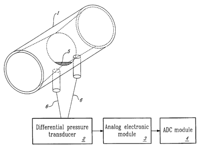
Fig. 1 is a schematic of the flowmeter containing the Gas Flow
Receiver, differential pressure transducer, analog electronic module and
ADC module;
Fig. 2 is the Gas Flow Receiver with star-like diaphragm (prior art);
Fig. 3 is the Gas Flow Receiver with the invented non-symmetrical
flow-resistive element;
Fig. 4 shows the measured back-pressure versus flow for both types
of the GFRs;
Fig. 5 shows the measured ratio r~ of differential pressures
generated by non-symmetrical and symmetrical flow resistive elements
versus flow;
CA 02422398 2003-02-28
WO 01/18496 PCT/CA00/01026
-14-
Fig. 6 shows deviations of experimentally-measured syringe volume
from its actual value obtained during "expiration" and "inspiration", at
different averaged flow rates for the GFR with symmetrical star-like
obstacle;
Fig. 7 shows deviations of experimentally-measured syringe volume
from its actual value obtained during "expiration" and "inspiration," at
different averaged flow rates for the GFR with invented non-symmetrical
flow-resistive element;
Fig. 8 is a schematic side view of the GFRs;
Fig. 9 is a schematic front view of the flow resistive element within
the GFR tube (viewed along the long axis of the tube);
Figs. 10 and 11 show the configuration of the invented differential
pressure and flov~r transducer containing two thermoanemometer-type flow
sensitive elements. The channel for flowing gas connects two elements in
series (Fig. 10), or in parallel (Fig. 11 );
Fig. 12 depicts a schematic of a single flow-sensitive element with
acceleration applied to it;
Fig. 13 shows an example of a more complex configuration involving
three flow-sensitive elements connected in a triangle;
Fig. 14 shows the configuration of two identically-aligned flow-
sensitive elements with flow passing through only one of them;
Fig. 15 shows (a) unfiltered, and (b) filtered output signals of the
flowmeter at low flows;
Fig. 16 is a block-diagram of the electronic module of the flowmeter;
Figs. 17 and 18 are flow charts describing the invented signal
processing;
Fig. 19 shows the reaction of the flowmeter to a flow impulse; and
Fig. 20 shows a calibration curve of the flowmeter.
CA 02422398 2003-02-28
WO 01/18496 PCT/CA00/01026
-15-
Description of the Preferred Embodiment
In the preferred embodiment, a gas flow receiver has a non-
symmetrical-flow-inducing diaphragm mounted in a flow tube and causes
non-symmetrical flow in the flow tube with an accentuated higher pressure
near an upstream orifice than would be sensed in a corresponding cross-
section of the flow tube and an accentuated lower pressure near a
downstream orifice. A gas flowmeter using thermoanemometer-type
transducers receiving gas flow from the upstream orifice is made immune
to vibration or acceleration, for example, by arranging a pair of the
transducers parallel to one another with the gas flow passing serially
through them, but in opposite directions. The resulting transducer signals
processed to cancel the effect of the vibration or acceleration. The
transducer output is amplified by a noisy amplifier which injects a
secondary signal prior to digital conversion using an ADC. The digital signal
is averaged over a sampling period to obtain a sample having a level of
precision greater than a minimum quantization value of the ADC. The
sampling period is varied as a function of the transducer's analog signal
amplitude, such that the sampling period is longer for lower amplitude
values and is shorter for higher amplitude values. The sampling period
variation provides signal filtering. Since the flowmeter has a non-linear
response, a calibrated output signal representing flow is obtained by
recording samples under a number of calibrated flows and obtaining an
analytical solution for the non-linear function, using the analytical solution
to
obtain calibrated values for all sample values, and, in operation, looking up
a calibrated value corresponding to a sample value. Having briefly
described the features of the preferred embodiment together, the individual
features will now be described hereinbelow in greater detail.
The present application describes a variety of inventive features
applicable to a gas flowmeter. These features improve the characteristics
of the flowmeter. Maximum effectiveness of the improvement can be
CA 02422398 2003-02-28
WO 01/18496 PCT/CA00/01026
-16-
reached when the inventions discussed below are implemented jointly and
are therefore presented together herein.
TUBE FOR CONVERSION OF GAS FLOW TO DIFFERENTIAL
PRESSURE
Fig. 1 shows a schematic view of the flowmeter containing GFR 1,
differential pressure transducer 2, analog electronic module 3 and ADC
module 4. The flow-resistive element 5 of the invented gas flow receiver
(GFR) 1 is designed to simultaneously obtain low overall back-pressure,
and high local differential pressure measured between two points inside the
GFR 1 for bi-directional flow measurement, for example in spirometry. The
local differential pressure is created by placing an obstacle 5 in the GFR 1,
directly between the two points inside the GFR 1 at which the differential
pressure is measured, as close as possible to the midpoint of the line
connecting these two points. In some circumstances, it may be desirable
for the obstacle or diaphragm to be positioned offset from the midpoint.
To prove the invented idea, two experimental GFRs have been
constructed. Each of the star-like symmetrical diaphragm 7 and the
invented non-symmetrical diaphragm 5 were placed in the middle of
identical tubes 120mm long with input inner diameter of 21 mm and inner
diameter of 19mm at the center of the tube (Figs. 2 and 3). The shapes of
the flow-resistive elements have been chosen so as to generate back
pressure lower then 150Pa~s/I (required by ATS standards for spirometry).
The six beams of the star-like diaphragm 7 have width of 1 mm each. The
central spot of the diaphragm has a diameter of 4mm. The non-symmetrical
diaphragm 5 has the shape of a circular segment with height of 4mm. The
star-like diaphragm 7 has thickness of 1 mm while the segment-type
diaphragm 5 has a thickness of 0.1-0.2mm.
Each of the GFRs was connected to the same differential pressure
transducer 2 and individually calibrated. Back pressure was measured by
CA 02422398 2003-02-28
WO 01/18496 PCT/CA00/01026
-17-
an additional pressure sensor. A 3-liter calibration syringe called "SpiroCal"
manufactured by Burdick Inc. (Milton, WI, USA), was used to generate gas
flows during the experiments. Fig. 4 shows the dependence of back
pressure on air flow, for the two GFRs. Fig. 5 depicts the ratio r~ = dP~ldP2
as function of flow, where dP~ and dP2 are differential pressures generated
by the GFRs with the invented non-symmetrical diaphragm 5, and
symmetrical star-like diaphragm 7, respectively. The invented GFR
generates lower back pressure and higher differential pressure than the
GFR with symmetrical diaphragm 7.
To check the sensitivity of the two tubes to gas velocity distribution
across the cross-section of the tube, the following two-step experiment was
performed. In the first step, each tube (after calibration) was connected to
the syringe, and gas was "inspired" from the ambient through the tube into
the syringe by piston strokes at different flow rates - "inspiration". The
inspired volume was measured by integrating flow measurements over
time, and compared with the actual volume of the syringe. In the second
step, each tube was rotated by 180 degrees, such that its flow direction
was reversed, and connected to the syringe with its opposite end, and the
same experiments were conducted except with gas being pumped out of
the syringe, by "expiration" piston strokes. Thus, the direction of gas flow
in
the tubes was the same, but the connections, and thus, the gas flow
velocity distributions in the flux, were different. In the first step, the GFR
input is connected directly to an infinite volume of ambient gas, while in the
second step the gas flux entering the GFR is shaped by a 40mm-long
connecting tube with inner diameter of 30mm. Deviations (in %) of
experimentally measured syringe volume from its actual value, obtained in
the regimes "expiration" and "inspiration" at different averaged flows, for
the
two tested GFRs, are presented in Figs. 6 and 7. The GFR with the star-
like diaphragm 7 demonstrated a discrepancy in measured volumes up to
8.5% due to changes of its orientation, which confirms its sensitivity to gas
velocity distribution across the cross-section of the tube. For the invented
CA 02422398 2003-02-28
WO 01/18496 PCT/CA00/01026
-18-
tube, these discrepancies did not exceed 1 %, which demonstrates
substantially lower sensitivity to gas velocity distribution across the cross-
section of the tube.
The invented GFR has a simpler shape than the GFR with
symmetrical star-like diaphragm or crest-type flow resistive element. This
can simplify its manufacturing and improve reproducibility of the conversion
characteristic.
The described embodiment confirms the advantages of the invented
solution. Meanwhile, other shapes of non-symmetrical flow-resistive
element can be used according to the invention. GFRs containing the
invented flow-resistive elements in the form of non-symmetrical circular
segments with heights of 3mm and 5mm, have been also tested.
Experimental results are shown in Figs. 4 and 5, represented by circular
and triangular symbols, respectively. These variations have also
demonstrated low sensitivity to gas velocity distribution across the cross-
section of the tube.
An increase of the thickness of the circular segment obstacle from
0.2mm to 1-2mm does not cause significant changes in the conversion
characteristics of the GFR. Observed deviations of back-pressure and local
differential pressure did not exceed 5%.
Figs. 8 and 9 show several possible designs of the GFR, which do
not exhaust all possible shapes of the GFRs. The particular choice of GFR
should be made to provide optimal adaptation to the given application and
manufacturing techniques. In Fig. 8, different cross-sections of flow-
resistive element 8, 9, 10 are shown inside the GFR 1. The GFR 1 may
also contain tubing 11 attached at a certain angle. Front views of plane
diaphragms 12, 13, 14 used as flow-resistive elements are shown in Fig. 9.
In the preferred embodiment, the flow measured is bi-directional. In
the case that the flow is in one direction, the positioning of the non-
CA 02422398 2003-02-28
WO 01/18496 PCT/CA00/01026
-19-
symmetrical diaphragm may preferably be in a position different from the
midpoint between the sensing tube orifices.
DIFFERENTIAL PRESSURE AND GAS FLOW TRANSDUCER WITH
IMMUNITY TO VIBRATIONS/ACCELERATION
Figs. 10 and 11 show two possible configurations of the invented
transducer, where two flow-sensitive elements 15 are connected in series
(Fig. 10), and in parallel (Fig. 11 ). In both cases, the gas flowing through
the channels passes through the flow-sensitive elements in opposite
directions. Therefore, the heated volumes of gas 16 near the heaters 17 in
both flow-sensitive elements 15 (shown as shaded circles), are also shifted
in opposite directions causing inverted output signal components. When
acceleration is applied in the direction parallel to gas flow as shown on Fig.
12, heated volumes of gas 16 are shifted in the same direction for both
flow-sensitive elements 15 causing increments in output signals which are
the same for both sensors. The output signals Vsensor~ and VSensor2 of the
two flow-sensitive elements 15 are then processed by electronic circuitry 3,
such that one signal is subtracted from the other. The following three
equations summarize the situation.
Usensorl = Uflow + Vacceleration
Usensor2 = -Uflow + Vacceleration
Vsensor1 - Vsensor2 = 2 'Uflow
where Vfiow and Vacceleration are the sensor output voltage components
caused by gas flow and applied acceleration, respectively.
If the two linear flow-sensitive elements 15 are identical, sensitivity
to acceleration of the whole transducer can be reduced theoretically to
zero. In practice, the immunity to acceleration may be limited by mismatch
of the two sensor elements 15 and calibration of their sensitivities.
The choice of schemes presented in Figs. 10 and 11 depends on the
particular application. The transducer with two flow-sensitive elements 15
CA 02422398 2003-02-28
WO 01/18496 PCT/CA00/01026
-20-
connected in series has flow impedance two times higher than a single
element, while the second transducer (Fig. 11 ) has flow impedance two
times lower.
For experimental verification of the invented concept, a prototype of
the transducer was assembled on the basis of two AWM2200 mass flow
sensors (Honeywell) connected in series by plastic hoses. The
performance of the assembled prototype was compared with the
performance of a single AWM2200 sensor. The electronic circuitries of the
transducers provided the same sensitivity to differential pressure. Then
both devices were rotated in the Earth's gravity. The single AWM2200
sensor has sensitivity to acceleration of 14mV/g while the prototype of the
invented transducer is completely immune to the same acceleration within
the resolution of the electronic circuitry (less than 1 mV). Both tested
transducers have the same sensitivity to gas flow.
The invented configuration of the transducer 2, immune to
acceleration, can be realized by a variety of methods. The best results may
be obtained by the usage of identical flow-sensitive elements. These flow-
sensitive elements may be commercially available sensors as described
above or specially designed functional sensing elements.
Among other possible configurations, one is shown in Fig. 13, where
three flow-sensitive elements are arranged in the same plane and
connected in the shape of a triangle. In this case, the output signals of each
flow-sensitive element can be written as:
Vsensor~ = Ufiow + Vacceteration'C~S(60° /J
Usensor2 = Ufiow '~' Vacceteration'C~S(60°+~
Usensor3 = -Uflow - Vacceleration'C~S~~
where ~3is the effective angle of the acceleration, as shown in Fig. 13.
This system of three equations with three unknown parameters,
Vfiow, Vacceleration and ,Q, can be solved to cancel the influence of the
acceleration-induced component of the signal.
CA 02422398 2003-02-28
WO 01/18496 PCT/CA00/01026
-21 -
Fig. 14 depicts another possible combination of two flow-sensitive
elements. The gas passage 18, which is opened to the main gas
passageway at one end allows the reference sensor to experience the
same gas composition, pressure and temperature, without experiencing the
gas flow. When conditions of gas composition, pressure and temperature
are constant, sensor 2 may be isolated without using the passage 18. In
this case, the following three equations summarize the sensors output
signals and the obtaining of the flow signal. The output signals of the
sensors are:
Usensorl - Uflow '~ Vacceleration
Usensor2 - Vacceleration
Usensorl - Vsensor2 - Uflow
Processing of the output signals can thus cancel the acceleration-
induced component of the signal.
The following points should be noted:
In addition to the described acceleration compensation,
compensation for variations in temperature, gas composition and ambient
pressure also may be implemented in ways typically used in mass-flow
controllers. Meanwhile, the invented acceleration suppression is effective
independently of the particular embodiment shown in Figs. 10, 11, 13, 14
and independent of the method of possible compensation of gas
temperature, gas composition and ambient pressure.
SIGNAL PROCESSING FOR IMPROVEMENT OF FLOWMETER
ACCURACY.
The invented method to improve flowmeter resolution at low flows
(which would otherwise limited by quantization noise of the ADC, unless
one is ready to use a high-resolution ADC), by special signal processing
was experimentally checked with a flowmeter containing a nonlinear GFR
1, described above, and mass flow sensor AWM2200, manufactured by
CA 02422398 2003-02-28
WO 01/18496 PCT/CA00/01026
-22-
Honeywell Inc. and connected to the GFR 1 by two plastic hoses 6. Sensor
excitation and signal amplification was performed by the circuitry
recommended by the manufacturer. The severe decrease of the flowmeter
sensitivity at low flows results from the near-square-law dependence of
differential pressure versus flow generated by the GFR 1. The limited
resolution of the ADC 4 restricts minimal detectable flow. At the same time,
parasitic vibration-caused signals are large enough to degrade accuracy of
the flowmeter at low flows. As an example, Fig. 15a shows the influence of
the intentionally generated vibrations of the pneumatic hoses 6. The
minimum detectable flow defined by the resolution of the ADC 4 (flow
corresponding to +1 mV or -1 mV, the quantization unit of the ADC) was
found to be approximately 50m1/s (without the invented signal processing).
In the described experiment, the electronic module contained a typical 12-
bit ADC 4 (AD7890-4). The digitized signal, with sampling rate dt =2ms,
was transferred to a personal computer for visualization, storage and
processing.
The reasonable useful frequency bandwidth of the electronic module
for the detection of variable flows, specified by the ATS standards, need
not be greater than 100-150Hz. To artificially increase the high-frequency
noise component of the analog output signal in accord with the invention
(as specified above in 3.2)), the frequency bandwidth of the electronic
module was intentionally increased up to 10kHz. The increased high-
frequency noise component of the analog output signal, determined by
approximately white noise of the operational amplifiers of the circuitry, had
amplitude of approximately ~3mV, equivalent to three quantization units of
the ADC 4. This added noise is shown in Fig. 15a. A schematic block-
diagram of the device is shown in Fig. 16. In the described experimentally-
checked embodiment, additional noise was generated inside the analog
circuitry module.
CA 02422398 2003-02-28
WO 01/18496 PCT/CA00/01026
-23-
Flow charts describing signal processing in the microprocessor
based module are shown in Figs. 17 and 18. To suppress signals due to
vibrations of the hoses 6 without degrading of the flowmeter dynamic
properties, the following filtering parameters were used. The operating flow
range of the flowmeter was divided into four sub-ranges:
0<flow<0.5 I/s;
0.5 I/s<flow< 1 I/s;
1 I/s<flow<2 I/s;
2 I/s<flow< 15 I/s.
The averaging time z was chosen to be 72ms (N~=36) for the first
sub-range, 30ms (N2=15) for the second sub-range, 12ms (N3=6) for the
third sub-range and 6ms (N4=3) for the fourth sub-range. In accord with the
first preferred embodiment (Fig. 17), after the analog voltage output of the
transducer is transformed by ADC into digital format, the corresponding
flow is found from the calibration curve of the flowmeter. Then flow
readings are stored in the buffer in such a way that at least the last N~
readings are in the buffer. The present flow is analyzed to find out which of
the four sub-ranges it belongs to. Depending on the result of the analysis,
flow is averaged through last N; readings stored in the buffer, if present
flow
belongs to sub-range i (i=1...4).
The effectiveness of presented signal processing is shown in Fig.
15b. The averaging of the signal allowed increase in flow resolution from
50m1/s to approximately 5ml/s. The suppression factor for vibration-
generated signals is approximately 7-8.
Another possible filtering sequence is shown in Fig. 18. The
difference of this signal processing from previous one is the following:
- four sub-ranges are defined in terms of voltage (not flow);
- averaging is done with voltage transformed into digital format;
CA 02422398 2003-02-28
WO 01/18496 PCT/CA00/01026
-24-
- resulting flow corresponding to averaged voltage is found from the
calibration curve of the flowmeter.
While very important at low flows, the described filtering procedure
may be redundant at higher flows because of the steep signal rise
proportional to approximately the square of flow. For example, a rise of flow
from 50m1/s to 2 I/s results in signal increase by a factor of 1600=402 which
is more than one order of magnitude higher than the usual parasitic signals
due to vibrations. On the other hand, the high frequency response of the
flowmeter is required mainly at high flows (for example, spirometry), which
would be degraded by a long averaging time z Thus, the usage of several
sub-ranges with low averaging times at high flows, maintains satisfactory
speed of response at medium and high flows. Fig. 19 shows the reaction of
the flowmeter to a flow impulse generated by a "SpiroCal" 3-liter syringe. At
high flows, the filtered signal (b) has the same shape as the unfiltered
signal (a). Its fall time is estimated to be less than 10ms. The effect of
filtering at low flows can be recognized by the effective suppression of the
oscillating acoustic signal generated by the collision of the piston with the
syringe bottom.
The parameters of this filtering method, i.e. number of flow sub-
ranges, averaging times and amplitude of the analog signal noise
component, can be chosen to optimize the operation of the flowmeter for a
particular application. The parameters of the investigated physical process
resulting in this choice are: required frequency response and flow operating
range of the flowmeter, and intensity and frequency spectrum of the
parasitic signals to be suppressed.
METHOD FOR FLOWMETER LINEARIZATION.
Typically, calibration of the flowmeter involves the following steps:
- measuring of the flowmeter output voltage at several reference flows;
CA 02422398 2003-02-28
WO 01/18496 PCT/CA00/01026
-25-
- calculation of an analytical function which fits the actual calibration
curve of the flowmeter;
- storage of the analytical function as:
- a table which gives unambiguous correspondence of all possible
ADC readings to flow;
- parameters of the analytical function which allow calculation of flow
for each ADC reading during the flowmeter operation.
Usually, a high precision flow generator is used to calibrate the
flowmeter at several reference flows. The number of these reference flows
should not exceed 10-20. Otherwise the calibration procedure would be
unacceptably long. On the other hand, even a 12-bit ADC which is typically
used in flowmeters measures 4096 voltage levels in the operating range of
the device. Therefore finding an analytical function which accurately fits the
actual calibration curve of the flowmeter and allows determination of flows
corresponding to all possible ADC readings, is critically important. Methods
of curve fitting are well-known and are not considered here.
The type of analytical function F(V) which gives optimal fitting for the
described flowmeter is disclosed:
N
r' ~Y~ - ~ f~i y ar s
i=1
where V is the output voltage of the flowmeter; N is greater than or equal to
3; parameters A; are coefficients determined experimentally; cz; are real
numbers (not necessary integer), typically greater than 1.
For verification of the invented linearization method, a prototype
flowmeter was used. The flow meter was based on the GFR 1 described
above, containing the 120mm long tube with input inner diameter of 21 mm
and inner diameter of 19mm at the center of the tube. A planar non-
symmetrical diaphragm 5 having the shape of a circular segment with
height of 4mm (Fig. 3), was used as a flow-resistive element. This
CA 02422398 2003-02-28
WO 01/18496 PCT/CA00/01026
-26-
diaphragm with thickness of 0.2mm was located at the center of the tube,
and generated differential pressure close to the square of the flow (square
transfer function). Mass flow sensor AWM2200 (Honeywell) was connected
to the GFR 1 with two plastic hoses 6 to measure flow-induced differential
pressure. The flowmeter also contained a 12-bit ADC AD7890-10 operating
in the range ~10V.
In accordance with the invention, the operating flow range of the
flowmeter was divided into two sub-ranges, 0 - 2 I/s and 2 - 15 I/s. The
coefficients A; of the calibration curve F(V) were found for N=5 and a;=2.
Two functions defined separately for the two sub-ranges are graphed in
Fig. 20. After calibration, the calibration curve was stored in form of the
table in a computer file.
For checking of the flowmeter accuracy, its GFR was connected to
the "SpiroCal" 3-liter calibration syringe. Then, air was pumped in and out
of the syringe with different flow rates by piston strokes. The expired and
inspired air volumes were measured by the flowmeter and compared with
the actual volume of the syringe. Deviations of these two volumes (in %)
shown in Fig. 7, do not exceed 2%. This confirms that the accuracy of the
flowmeter is within 2% or better, exceeding the requirements specified by
the ATS standards for spirometry.
In practice, the choice of the parameters N and a; may differ from
those used in the example presented herein, depending on the
applications. For example, the linearization procedure was also
successfully tested with N=6, although the algorithm of finding of
coefficients A; was more complicated.
The parameters a; can be chosen so as to give better fitting of the
calculated calibration curve with actual flow response of the flowmeter. At
low flows, the dominant contribution is given by the first element of the
sum: F(V) ~ A,Va~ . Transforming this equation, one obtains V ~ bFa~ . In
CA 02422398 2003-02-28
WO 01/18496 PCT/CA00/01026
-27-
this case, the parameter a~ defines conversion from flow to output voltage
at low flows, which mainly depends on the construction of the GFR 1.
Usually, the GFR 1 with diaphragm-type flow-resistive elements 5
generates differential pressure which varies near to the square of flow
(square transfer function). For these types of GFRs 1, a~=2 gives a
reasonable approximation of the calibration curve. Nevertheless some
deviations of the parameter a~ as well as parameters a; (1 <i<N) from the
value of 2 are also included in the invented linearization method.
Depending on the accuracy requirements and flow operating range,
the number of sub-ranges may also vary from one to some number greater
than two. This choice depends on the particular application.