Note: Descriptions are shown in the official language in which they were submitted.
CA 02422716 2003-03-12
WO 03/013773 PCT/USO1/24816
-1-
Description
TOOTH-AND-HOLDER HARVESTING HEAD DISK SAW
Technical Field
This invention relates generally to a disk
saw and more specifically to a tooth and holder
arrangement for such a disk saw.
Background Art
Logging operations commonly use a work
machine, such as a feller-buncher, to harvest trees.
These work machines are generally equipped with a
harvesting head containing a disk saw, which does the
actual cutting of the tree. Due to the hostile
operating environment in a forest, the teeth of the
disk saw often become dull or break, necessitating
sharpening or replacement. The teeth of the disk saw
are commonly made to be replaceable and mount to a
tooth holder (also separately replaceable) which is
then mounted to the disk saw. An example of this type
of tooth and holder arrangement is shown in U.S.
Patent No. 5,211,212, issued May 18, 1993 to Carlson
et al. (hereafter referenced as '212).
'212 provides for a replaceable holder with
two replaceable cutting teeth. The tooth and holder
arrangement disclosed in '212 includes many different
pieces. Since a forest work site is often in a remote
location, the unavailability of one or more of these
CA 02422716 2003-03-12
WO 03/013773 PCT/USO1/24816
-2-
many pieces can cause undue downtime for a work
machine and operator, which can be quite costly.
Several of the pieces of the '212 device are also
relatively small, requiring the operator to exercise
extra caution when replacing the tooth or holder so
that the small places do not become misplaced in the
debris on the forest floor. Additionally, the head of
the bolt attaching the tooth to the holder is located
on the leading face of the assembly, which can cause
contact damage or debris buildup when the tooth is
cutting into a tree. The bolt holding the holder to
the saw disk must be precisely aligned with the nut
and washer inside an axial hole in the saw disk, and
the nut and washer, along with the holder and bolt,
can be awkward for the operator to hold and
manipulate. Any of these conditions can cause time-
consuming and frustrating difficulties when the tooth
and/or holder need to be replaced. The axial hole in
the saw disk also could be a stress concentrator and
weaken the disk. The arrangement of the holder of
'212 causes all forces perpendicular to the direction
of saw disk travel to be transferred from the holder
to the saw disk through the bolt and the dowels shown,
which could cause shearing damage to the bolt and
dowels.
The present invention is directed to
overcoming one or more of the problems as set forth
above.
CA 02422716 2003-03-12
WO 03/013773 PCT/USO1/24816
-3-
Disclosure of the Invention
In one aspect of the present invention, a
disk saw is provided that has a rim and at least one
disk slot. A holder is provided that has a holder
bolt hole and that is positioned in a substantially
radial direction to the axis A and is aligned with the
at least one disk slot.
In another aspect of the present invention,
a tooth holder for use in a forestry application is
provided. The tooth holder comprises a holder top
face, a contoured base face opposite the holder top
face, a tooth end face extending between the base face
and the holder top face, a holder end face opposite
the tooth end face, and at least one inner side face
located adjacent to and extending beyond the contoured
base face in a direction away from the holder top
face .
In another aspect of the present invention,
a method for detachably attaching a tooth and holder
to a saw disk is disclosed. This method comprises
steps of positioning the holder in a disk slot on an
edge of the saw disk, mating a contoured holder base
face with a contoured disk slot face, overlapping an
inner side face of the holder with the disk slot face
in direct contact with a rim of the saw disk,
inserting a fastener through a holder bolt hole in the
holder and into the disk, placing a tooth against the
holder, and inserting a fastener through the holder
CA 02422716 2003-03-12
WO 03/013773 PCT/USO1/24816
-4-
and into the tooth such that it passes through the
holder bolt hole.
Brief Description of the Drawings
Fig. 1 is a perspective view of a disk saw
illustrating an embodiment of the present invention.
Fig. 2a is an exploded perspective view of a
tooth, holder, and saw disk of an embodiment of the
present invention.
Fig. 2b is a perspective view of a tooth and
holder of another embodiment of the present invention.
Best Mode for Carrvina Out the Invention
A disk saw 100 used in a forestry
application is provided, as shown in Fig. 1. The disk
saw 100 includes a saw disk 102 having a rim 104 and a
center portion 106. The rim 104 is an area generally
near the circumference of the saw disk 102. The rim
104 may be thicker than the center portion 106 and may
extend beyond the center portion 106 on one or both
sides of the saw disk 102, a quality hereafter
referenced as "raised". The saw disk 102 is centered
about an axis A. The disk saw 100 may be mounted to a
harvesting head such that it revolves about the axis
A. The disk saw 100 also includes at least one tooth
108 and at least one holder 110, and preferably a
plurality of teeth 108 and holders 110 for efficient
and balanced cutting.
The saw disk 102 includes one or more disk
holes 112. The disk holes 112 penetrate partially
CA 02422716 2003-03-12
WO 03/013773 PCT/USO1/24816
-5-
into the rim 104 and are associated with one or more
disk slots 114. The disk holes 112 may be in a
substantially radial direction to the axis A, as
shown, or may be tilted relative to the rim 104
without departing from the spirit of the present
invention. Each disk hole 112 can be located
equidistant from the sides of the rim 104 so that it
is centered on the rim 104.
The disk slots 114 are contoured to form a
void of a predefined shape in the rim 104 of the saw
disk 102. Each disk slot 114 is contoured to accept,
in a nesting.or mating relationship, a base face 200
of a holder 110. The disk slot 114 may have one of a
number of different configurations. An example of a
possible configuration is the three-sided disk slot
114 with filleted corners shown in Fig. 2. The
parallel sides can be perpendicular to the bottom side
or one or both sides can be canted to allow for
greater stress distribution from the holder 110. Many
disk slot 114 configurations not mentioned could also
have advantages, as is obvious to one skilled in the
art, and are not excluded by the present invention.
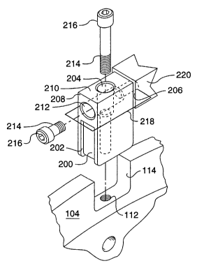
The base face 200 of the holder 110 is
adjacent at least one inner side face 202. When the
base face 200 is mated and in contact with the disk
slot 114, each inner side face 202 contacts the rim
104 of the saw disk 102 in an overlapping
relationship. By "overlapping", it is meant that at
least a portion of the inner side face 202 is located
outside the disk slot 114, as shown in Figs. 1 and 2a.
CA 02422716 2003-03-12
WO 03/013773 PCT/USO1/24816
-6-
The holder 110 also includes a holder bolt hole 204, a
tooth end face 206, a holder end face 208 opposite the
tooth end face 206, a holder top face 210 opposite the
base face 200, and a tooth bolt hole 212. The holder
bolt hole 204 extends from the holder top face 210
through the holder 110 to the base face 200. The
tooth bolt hole 212 extends from the holder end face
208 through the holder 110 to the tooth end face 206.
The holder bolt hole 204 has a decreased
radius forming a bolt hole shoulder at a predetermined
distance from the holder top face 210. A fastener
214, described here as, but not limited to, a bolt 214
has a bolt head 216. When the base face 200 of the
holder 110 is placed into a mating relationship with
the disk slot 114, a holder bolt hole 204 meets up
with a disk hole 112. There may be more than one
holder bolt hole 204 and disk hole 112 pair per holder
110. The fastener 214 is then inserted into the
holder bolt hole 204 from the holder top face 210 and
engages the disk hole 112. One way that this
engagement can be accomplished is that the fastener
214 and one or both of the holder bolt hole 204 and
the disk hole 112 is threaded and the fastener 214
threadably engages with the threaded holder bolt hole
204 and/or disk hole 112 in a known manner. When the
fastener 214 is tightened to a predetermined torque,
the bolt head 216 contacts the bolt hole shoulder (not
shown). The distance of the bolt hole shoulder from
the holder top face 210 is predetermined to allow the
fastener 214 to be fully recessed into the holder bolt
CA 02422716 2003-03-12
WO 03/013773 PCT/USO1/24816
hole 204 when the fastener 214 is tightened. The bolt
hole shoulder should be located a sufficient distance
from the holder top face 210 that the fastener 214,
when fully recessed, does not protrude above a bolt
hole plane 218 defined parallel to the holder top face
210 and tangent to the portion of the tooth bolt hole
212 furthest from the holder top face 210.
It can also be easily seen that another
embodiment of the present invention could use a
partial bolt hole (not shown) which does not extend
fully through the holder to accept a dowel (not shown)
extending from a disk hole 112 in a known manner, in
combination with at least one fastener arrangement as
described above.
In one embodiment of the present invention,
the tooth bolt hole 212 has a decreased radius forming
a bolt hole shoulder (not shown) at a predetermined
distance from the holder end face 208. A fastener
1214, described here as, but not limited to, a bolt 214
has a bolt head 216. When a tooth 108 is placed into
a contact with the holder 110, a tooth bolt hole 212
meets up with a tooth hole 220. The fastener 214 is
then inserted into the tooth bolt hole 212 from the
holder end face 208 and engages the tooth hole 220.
One way that this engagement can be accomplished is
that the fastener 214 and one or both of the tooth
bolt hole 212 and the tooth hole 220 is threaded and
the fastener 214 threadably engages with the threaded
tooth bolt hole 212 and/or tooth hole 220 in a known
manner. When the fastener 214 is tightened to a
CA 02422716 2003-03-12
WO 03/013773 PCT/USO1/24816
_g_
predetermined torque, the bolt head 216 contacts the
bolt hole shoulder. The distance of the bolt hole
shoulder from the holder end face 208 is predetermined
to allow the fastener 214 to be fully recessed into
the tooth bolt hole 212 when the fastener 214 is
tightened in this embodiment.
In an alternative embodiment of the present
invention, the diameter of the bolt head 216 is larger
than the diameter of the tooth bolt hole 212 and the
tooth bolt hole 212 does not include a bolt hole
shoulder. The bolt head 216 directly contacts the
holder end face 208 when tightened. This embodiment
enables the holder 110 to be reversible; that is, it
can be turned end-to-end such that the holder end face
208 can be interchangeable with the tooth end face
206.
While aspects of the present invention have
been particularly shown and described with reference
to the preferred embodiments above, it will be
understood by those skilled in the art that various
additional embodiments may be contemplated without
departing from the spirit and scope of the present
invention.
Industrial Applicability
In operation, a disk saw 100 has a holder
110 and tooth 108 attached firmly to each disk slot
112 of the saw disk 102. The disk saw 100 rotates
rapidly within, for example, a harvesting head carried
by a work machine and directed by an operator. As a
CA 02422716 2003-03-12
WO 03/013773 PCT/USO1/24816
-9-
tooth 108 wears or breaks during use, the operator
will stop the machine and turn the disk saw 100 so
that the worn or broken tooth 108 is in an accessible
location. The operator then removes the debris, if
any, that has accumulated in the tooth bolt hole 212
behind the fastener 214 with a simple hand tool such
as an awl. The operator then removes the fastener 214
and turns the tooth 108 to an unused side in a known
manner. If the tooth 108 does not include an unused
side, the operator instead places a new tooth 108 on
the holder 110. The operator then inserts the
fastener 214 through the tooth bolt hole 212 and into
the tooth hole 220. The operator next tightens the
fastener 214 until the bolt head 216 contacts the bolt
hole shoulder at the predetermined torque and the
fastener 214 is wholly inside the tooth bolt hole 212.
After the fastener 214 is tightened properly, the disk
saw 100 may be placed back into service.
If the holder 110 is damaged or worn and
must be replaced, this replacement can be accomplished
when the tooth. 108 is separated from the holder 110.
The operator first removes the debris, if any, that
has accumulated in the holder bolt hole 204 behind the
fastener 214 with a simple hand tool such as an awl.
The fastener 214 is then removed by the operator,
which allows the base face 200 of the holder 110 to be
disengaged from its mating relationship with the disk
slot 114. If the holder 110 is of the reversible type
and includes an undamaged side, it may be removed and
placed back in a reversed position in the disk slot
CA 02422716 2003-03-12
WO 03/013773 PCT/USO1/24816
-10-
114. Otherwise, the operator positions a second
holder 110 in the disk slot 114 such that its base
face 200 is in a mating relationship with the disk
slot 114. This step will cause the inner side face
202 to overlap the disk slot 114 and contact the rim
104 of the saw disk 102. The operator then inserts
the fastener 214 through the holder bolt hole 204 and
into the disk hole 112. The operator next tightens
the fastener 214 until the bolt head 216 contacts the
bolt hole shoulder at the predetermined torque and the
fastener 214 is wholly inside the holder bolt hole
204. After the fastener 214 is tightened properly,
the tooth 108 may be replaced as above and the disk
saw 100 may then be placed back into service.
The present invention eliminates multiple
small parts with close alignments, which can be easily
misplaced in a debris-filled forest environment. One
or both o-f the fasteners 214 is located in a recessed
and protected location to avoid damage to the fastener
214. Even if debris should enter the tooth or holder
bolt holes 212,204 atop the fastener 214, it will not
pack in tightly. This debris can be easily brushed
out by hand or through the use of a hand tool. Damage
to the fastener 214 caused by contact with the tree
being felled is also avoided. The base face 200
transfers forces in the plane of the disk to the rim
104, while each inner side face 202 transfers forces
perpendicular to the plane of the disk to the rim 104.
CA 02422716 2003-03-12
WO 03/013773 PCT/USO1/24816
-11-
Other aspects, objects, and advantages of
this invention can be obtained from a study of the
drawings, the disclosure, and the appended claims.