Note: Descriptions are shown in the official language in which they were submitted.
CA 02422888 2003-03-19
WO 02/24542 PCT/US01/42034
-1-
VENTING PLASTIC CLOSURE
The present invention relates generally to a plastic closure for use
with an associated container, and more particularly to an internally threaded
plastic
closure having at least one container-engaging stop element for limiting
sealing
engagement of the closure with the container, thereby facilitating venting of
gas
pressure from within the container, and removal of the closure from the
container
by consumers. The present invention also contemplates a method of packaging a
hot-fill beverage which facilitates venting of gas pressure.
Threaded plastic closures have found very widespread application for
use in connection with bottles and like containers by virtue of their
economical
manufacture and sealing performance. Closures of this nature typically include
an outer plastic closure cap having an internal thread formation, and a
sealing
liner positioned adjacent the inside surface of a top wall portion of the
outer cap.
As the closure is threadingly applied to an associated container, the sealing
liner
is urged into sealing engagement with the sealing container. Threaded fitment
of
the closure to the container facilitates initial application of the closure,
as well as
re-application of the closure to the container by consumers after partial
consumption
of the container's contents.
While closures of the above type have proven very commercially
successful, over-application of the closures to containers can be problematic.
When closures are applied to containers, either by high-speed capping
equipment or
by consumers, closures can be applied with a torque which exceeds that
required for
effecting the desired sealing engagement with the associated container. As
will be
appreciated, over-application can undesirably result in closures which are
difficult
for consumers to remove. This problem has been recognized in connection with
closures having multi-lead thread formations, which are sometimes used on so-
called
"hot-file" beverages, that is, those filled at elevated temperatures. To
control
application, these types of closures typically have external marks ("pull-
ups") that
are used with reference to marks on the container finish to indicate the
degree to
which the closure has been applied.
Apart from high removal torque, over-application of closures can be
of concern in connection with the build-up of gas pressure within a container,
such
CA 02422888 2003-03-19
WO 02/24542 PCT/US01/42034
-2-
as the result of product fermentation caused by spoilage. Over-application of
a
closure can undesirably inhibit the closure's venting characteristics. This
occurs
because the degree of sealing engagement between the closure and the container
is
beyond that which is necessary to achieve sealing integrity under normal
conditions.
As a consequence, deformation of the closure under the influence of internal
gas
pressure is insufficient to move the closure out of sealing engagement with
the
container.
The present invention is directed to an improved closure construction
for a container which facilitates closure removal and venting of internal gas
pressure
by obviating problems associated with over-application of the closure.
A venting plastic closure embodying the principles of the present
invention is particularly suited for use with an associated container having
contents which ferment or otherwise spoil, resulting in the creation of
internal
gas pressure within the container. By virtue of the closure's configuration,
venting of gas pressure from within the container to acceptable levels is
accommodated. The closure is configured to facilitate venting even in the
event
of over-application of the closure to the container, such as can occur
attendant to
the use of high-speed automated capping equipment, as well as facilitating
convenient closure removal by consumers. A method of packaging a hot-fill
beverage is also disclosed.
A venting plastic closure embodying the principles of the present
invention includes an outer plastic cap having a top wall portion, and a
depending annular skirt portion. The skirt portion includes at least one
internal
thread formation and may include plural, multi-lead threads.
The closure includes a disc-shaped sealing liner positioned on an
inside surface of the top wall portion, with the liner configured for sealing
engagement with the associated container. To this end, the liner is spaced
inwardly
of the annular skirt portion, and includes a depending annular sealing bead
having a
generally downwardly and outwardly facing sealing surface. This sealing
surface is
configured for sealing engagement with a generally upwardly and inwardly
facing
portion of the associated container, to form what is referred to as a
"top/inside seal".
In accordance with the present invention, the outer plastic cap of the
CA 02422888 2009-05-27
65919-107
-3-
present closure includes at least one positive stop element engageable with
the
associated container. The stop element may be configured in various forms in
accordance with the present invention. In accordance with one form, a
plurality
of circumferentially spaced stop elements depend from the inside surface of
the
top wall portion. In accordance with the preferred embodiment, each stop
element
has a generally downwardly, facing stop surface engageable with the associated
container. In an alternate embodiment, the positive stop element is positioned
on
the closure skirt portion, preferably adjacent the thread formation of the
closure for
engagement with a cooperating thread formation on the associated container.
When
the closure is configured to include a plurality of thread formations, the
closure may
include a like plurality of stop elements respectively positioned adjacent the
thread
formations.
Features of the present closure facilitate efficient sealing with the
associated container. In the preferred form, the outer plastic cap includes an
annular liner support element which depends from the inside surface of the top
wall portion. The support element is positioned within the annular sealing
bead
of the sealing liner, positioned inwardly of and generally parallel to the
generally
downwardly and outwardly facing sealing surface of the sealing liner. The
sealing
liner is preferably efficiently formed by compression molding, and preferably
includes a relatively thin central panel portion; positioned inwardly of the
annular
sealing bead, for efficient use of liner material.
In one form, the annular stop elements depending from the inside
surface of the top wall portion are positioned radially outwardly of the
sealing liner,
whereby each stop surface of each stop element is exposed for engagement with
the associated container. In an alternate embodiment, the stop element depends
from the inside surface of the top wall beneath the sealing liner, and thus
cooperation with the container, while the surface of the stop element does not
actually contact the container.
CA 02422888 2009-05-27
65919-107
- 3a -
In particular according to one aspect of the present invention, there
is provided a venting plastic closure for use with an associated container,
said
closure comprising: an outer plastic cap having a top wall portion, and a
depending annular skirt portion having an internal thread formation; and a
disc-
shaped sealing liner positioned on an inside surface of said top wall portion,
said
liner being spaced inwardly of said annular skirt portion, and including a
depending annular sealing bead having a generally downwardly and outwardly
facing sealing surface for sealing engagement with a generally upwardly and
inwardly facing portion of an associated container; said outer plastic cap
including
an annular liner support element depending from the inside surface of said top
wall portion, said liner support element being positioned within said annular
sealing bead of said sealing liner, said outer plastic can further including
at least
one positive stop element engageable with said associated container after said
sealing bead portion has been positioned in sealing engagement to facilitate
closure removal and venting of gas pressure from within said container.
In particular according to another aspect of the present invention,
there is provided a venting plastic closure for use with an associated
container,
comprising: an outer plastic cap having a top wall portion, and a depending
annular skirt portion having at least one internal thread formation; and a
disc-
shaped sealing liner positioned on an inside surface of said top wall portion,
said
liner being spaced inwardly of said annular skirt portion, and including a
relatively
thin central panel portion and a depending annular sealing bead having a
generally downwardly and outwardly facing sealing surface for sealing
engagement with a generally upwardly and inwardly facing portion of said
associated container; said plastic cap including an annular liner support
element
depending from the inside surface of said top wall portion, said liner support
element defining a liner support surface positioned inwardly of the sealing
surface
of said sealing liner; said outer plastic cap including an annular liner
support
element depending from the inside surface of said top wall portion, said liner
support element being positioned within said annular sealing bead of said
sealing
liner, said outer plastic cap further including at least one positive stop
element
engageable with said associated container, said stop element depending from
the
CA 02422888 2009-05-27
65919-107
- 3b -
inside surface of said top wall portion, said stop element having a generally
downwardly facing stop surface for cooperation with said container.
In particular according to a further aspect of the present invention,
there is provided a method of packaging a hot-fill beverage, comprising the
steps
of: providing a container; providing a plastic closure including an outer cap
having
a top wall portion and an annular depending skirt portion, and a disc-shaped
sealing liner positioned on an inside surface of said top wall portion spaced
inwardly of said skirt portion, said liner including a depending annular-
sealing
bead, said outer cap including an annular liner support element depending from
the inside surface of said top wall portion, said liner support element being
positioned within said annular sealing bead of said sealing liner, said outer
plastic
can further including at least one positive stop element engageable with said
container; filling said container with said beverage; and applying said
closure to
said container so that said sealing bead of said disc-shaped liner engages a
generally upwardly and inwardly facing portion of said container, and so that
said
positive stop element thereby cooperates with said container to limit sealing
engagement of said sealing bead with said container to thereby facilitate
venting
of gas pressure from within said container.
Other features and advantages of the present invention will become
readily apparent from the following detailed description, the accompanying
drawings, and the appended claims.
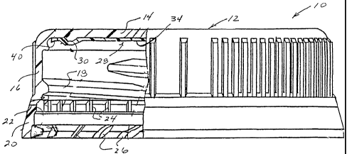
FIGURE 1 is a side elevational view, in partial cross-section, of a
CA 02422888 2009-05-27
65919-107
-4-
venting plastic closure embodying the principles of the present invention;
FIGURE 2 is a fragmentary, cross-sectional view of the venting
plastic closure shown in FIGURE 1;
FIGURE 2a is a diagrammatic view of the inside surface of the
closure cap top wall portion;
FIGURE 3 is a fragmentary, cross-sectional view of an alternate
embodiment;
FIGURE 4 is a fragmentary, cross-sectional view of a further
alternate embodiment of the present venting plastic closure;
FIGURE 5 is a fragmentary, cross-sectional view of a further
alternate embodiment of the present venting closure; and
FIGURE 6 is a finite element analysis of a venting plastic closure
configured in accordance with the present invention.
While the present invention is susceptible of embodiment in various
forms, there is shown in the drawings, and will hereinafter be described,
presently
preferred embodiments, with the understanding that the present disclosure is
to be
considered as an exemplification of the invention, and is not intended to
limit the
invention to the specific embodiments illustrated.
With reference first to FIGURES 1 and 2, therein is illustrated a
venting plastic closure 10 embodying the principles of the present invention.
Plastic
closure 10 has been particularly configured for use on bottles or like
containers,
such as container C, containing beverages or other liquids. The present
closure
has been particularly configured for use on so-called "hot-fill" beverages,
that is,
beverages which are introduced into an associated container during packaging
when the beverage is at a relatively elevated temperature. However, the
present
closure construction can be advantageously employed on containers having other
types of contents.
While the present closure construction can be manufactured by
various techniques, manufacture of the present closure by compression molding
is
presently preferred. U.S. Patent No. 4,497,765,
discloses a method and apparatus for forming plastic closures including in
situ
compression molded liners.
CA 02422888 2009-05-27
65919-107
-5-
Venting plastic closure 10 includes an outer plastic cap 12 having a
top wall portion 14, and annular skirt portion 16. The skirt portion 16
includes at
least one internal thread formation 18 configured for engagement with a
cooperating
container thread formation T. Plural, multi-lead thread formations can be
advantageously employed for obtaining the desired closure retention, while
permitting the closure to be removed from the container with minimum relative
rotation.
In the illustrated form, the plastic closure 10 is configured to provide
tamper-evidence. The closure includes a pilfer band 20 depending from annular
skirt portion 16. The pilfer band is distinguished from the skirt portion 16
by
circumferentially extending score line 22, which extends inwardly to a
plurality
of internal frangible ribs or bridges 24 which at least partially detachably
connect the pilfer band 20 to the skirt portion 16. The pilfer band 20
includes a
plurality of circumferentially spaced, inwardly extending flexible projections
26
which are configured for cooperative engagement with a locking ring L of
container
C such that during closure removal, the engagement of the projections 26 with
the
locking ring L results in breakage of bridges 24, and at least partial or
complete
separation of the pilfer band 20 from the skirt portion 16. The closure pilfer
band
can be configured in accordance with U.S. Patent No. 4,418,828, hereby
incorporated by reference. It is to be understood that the closure pilfer band
can be
otherwise configured, such as in accordance with the teachings of U.S. Patents
No.
4,938,370, to McBride, and No. 5,004,112, to McBride.
In order to effect the desired sealing cooperation with an associated
container, venting plastic closure 10 includes a disc-shaped sealing liner 28
positioned adjacent the inside surface of top wall portion 14 of closure cap
12.
The sealing liner is preferably compression molded within the outer closure
cap
during closure manufacture, and is configured for effecting a so-called
"top/inside seal" with the associated container C. To this end, the sealing
liner
includes a depending annular sealing bead portion 30 having a generally
downwardly and outwardly facing sealing surface 32, shown in an undeformed
configuration in FIGURE 2 in relation to a generally upwardly and inwardly
CA 02422888 2003-03-19
WO 02/24542 PCT/US01/42034
-6-
facing portion of the associated container C. When formed in accordance with
the preferred compression molding technique, the sealing liner 28 includes a
relatively thin central panel portion 34 positioned inwardly of sealing bead
30.
In the preferred form, the outer closure cap includes an annular liner
support element 36 depending from the inside surface of top wall portion 14.
The
liner support element is positioned within the annular sealing bead 30 of
liner 28,
and defines a liner support surface 38 positioned inwardly of and generally
parallel
to sealing surface 32 of liner 28. The liner support element 36 cooperates
with the
sealing bead 30 of sealing liner 28 to effect sealing engagement of the
sealing bead
with the surface of the associated container C, and also desirably reduced the
quantity of relatively expensive liner material employed in the closure.
As discussed, fermentation or other spoilage of the contents of
container C can occasionally take place. As a consequence, gas pressure within
the
container can become elevated, with it therefore being desirable for the
closure 10
to flex and deform outwardly to a sufficient degree such that the sealing
liner
28 is dislodged from sealing engagement with the associated container. Under
such
circumstances, gas pressure from within the container can be vented to the
atmosphere.
In accordance with the present invention, the closure 12 is configured
to facilitate such venting of gas pressure by obviating problems associated
with
over application of closures to containers. Such over application can preclude
the sealing liner of a closure from becoming sufficiently disengaged from the
associated container as to permit venting. To this end, a plastic closure
configured
in accordance with the present invention includes at least one positive stop
element
engageable with the container for limiting the sealing engagement between the
closure and the associated container. In accordance with the embodiment
illustrated
in FIGURE 1, the outer closure cap 12 includes at least one, and preferably a
plurality, of positive stop elements 40 depending from the inside surface of
the top
wall portion 14. In this embodiment, each stop element 40 is positioned
radially
outwardly of sealing liner 28, and is positioned for engagement with a
generally
upwardly facing surface of the associated container C. Accordingly, each stop
element 40 defines a generally downwardly facing stop surface, which in the
CA 02422888 2003-03-19
WO 02/24542 PCT/US01/42034
-7-
illustrated form, is non-horizontal, extending angularly upwardly and inwardly
so
that the stop surface faces generally downwardly and inwardly. Thus, in
cross-section, the stop element 40 is generally trapezoidal.
While it is within the purview of the present invention that the stop
element 40 be provided in the form of a continuous annulus, it is presently
preferred
that a plurality of circumferentially spaced stop elements be provided
depending
from the top wall portion 14. As illustrated in FIGURE 2a, a plurality of stop
elements 40 can be provided, spaced circumferentially at 45 intervals. Each
stop
element is configured to subscribe an angle of about 30 degrees. The specific
number of stop elements may be varied in keeping with the principles disclosed
herein.
With particular reference to FIGURE 6, therein is illustrated a finite
element analysis of a plastic closure configured in accordance with the
present
invention, including a stop element 40 having an inwardly and upwardly angled
stop surface (this illustrated closure does not include an annular support
element
36 positioned within sealing bead 30 of liner 28). By this illustration, the
cooperative action of stop element 40 with container C, and the associated
sealing liner 28, is readily apparent. By cooperation of the stop element with
the
finish of the associated container, the stop element 40 acts to limit the
sealing
engagement created between the sealing bead 30 of liner 28 and the finish of
the
container C. Venting of gas pressure from within the container is thus
facilitated.
Additionally, because sealing engagement of the closure and the container is
limited,
removal of the closure from the container by consumers is facilitated.
With reference to FIGURE 3, therein is illustrated an alternate
embodiment of the present closure 10, including an alternately configured stop
element, designated 50. In this embodiment, the stop element 50 depends from
the top wall portion 14, but is positioned beneath sealing liner 28. Thus, the
stop
element itself does not engage the associated container C, but rather acts
through
the sealing liner 28 to limit engagement of the closure liner with the
associated
container. As in the previously-described embodiment, a plurality of the stop
elements 50 are preferably provided depending from the inside surface of top
wall
portion 14, positioned in circumferentially spaced relationship on the inside
surface
CA 02422888 2003-03-19
WO 02/24542 PCT/US01/42034
-8-
of the top wall portion.
FIGURE 4 illustrates a further alternate embodiment of the present
closure 10, including a positive stop element 60 engageable with container C.
In
this embodiment, the stop element 60 is positioned on the interior surface of
skirt
portion 16 adjacent to closure thread 18, and is thus positioned for
engagement with
the leading portion of the container thread T. As in accordance with the
previous
embodiments, engagement of positive stop element 60 with the container C acts
to
limit sealing engagement of the closure with the container, thus facilitating
release
gas pressure from within the container, and removal of the closure from the
container by consumers. If the closure and the container are configured to
include a
plurality of thread formations, i.e., multi-lead threads, it is contemplated
that a like
plurality of the stop elements 60 be provided respectively positioned adjacent
each
of the thread formations for respective engagement with the thread formations
on
the container C.
FIGURE 5 illustrates a further alternate embodiment of the present
closure 10, including a stop element 70 engageable with container C. Like the
previously-described embodiment, this stop element is positioned on the
interior
surface of the skirt portion 16 of the closure, but generally at the juncture
of the
skirt portion 16 and top wall portion 14 in spaced relationship to thread
formation
18. Stop element 70 is configured for positive engagement with the container
thread T, but generally acts against an upwardly facing surface of the
container
thread.
Thus, an improved venting closure is disclosed which facilitates
release of gas pressure from within an associated container, and facilitates
removal
of the closure from a container by consumers. In each of the illustrated
embodiments, the one or more positive stop elements are configured. such that
they
do not act to limit closure application until the annular bead portion 30 of
the
sealing liner 28 has compressed sufficiently to effect a hermetic seal. This
is
illustrated in the finite element analysis illustration of FIGURE 6, wherein
the
sealing bead 30 is illustrated after initial contact of the positive stop 40
with the
finish of container C. Testing has shown that by providing one or more
positive
stops in the closure 10, the stops increase the application torque by three to
four
CA 02422888 2003-03-19
WO 02/24542 PCT/US01/42034
-9-
times to achieve the degree of sealing angle, in comparison to a similarly
configured
closure without positive stops. This desirably permits a bottler to
effectively use
static torque to prevent over-application.
Testing has further demonstrated that when the positive stop elements
are positioned to depend from the top wall portion, and the one or more
positive
stops of the closure become fully engaged with the top of the container
finish,
the venting pressure actually decreases as the closure is further applied. It
will
be appreciated from the finite element analysis that this decrease in venting
pressure occurs as the one or more stops act to lift the liner 28 away from
the
container finish as the closure is further applied to the container.
From the foregoing, numerous modifications and variations can be
effected without departing from the true spirit and scope of the novel concept
of
the present invention. It is to be understood that no limitation with respect
to the
specific embodiments illustrated herein is intended or should be inferred. The
disclosure is intended to cover, by the appended claims, all such
modifications as
fall within the scope of the claims.