Note: Descriptions are shown in the official language in which they were submitted.
- 1 -
LEVEL MONITORING SENSOR APPARATUS,
SOLID STRUCTURE SENSOR APPARATUS,
AND PENDULUM SENSOR APPARATUS
TECHNICAL FIELD
fooon7 The present invention generally relates to
sensors used on structures to monitor, particularly but not
exclusively, level variations in magnitude, orientation, and
deformation resulting from, for example, deflection or tilt.
BACKGROUND ART
Looo27 Sensors of all types are installed on large-
scale structures to measure parameters such as level
variation, deformation and tilt; resulting from a plurality
of internal factors, e.g., material quality, foundations,
and external factors, e.g., wind, temperature variations,
earthquakes, landslides, ice and snow build-up. The sensors
are provided to ensure the safety of occupants or users of
the large-scale structures, by monitoring unusual variations
in the above-described parameters, which could cause severe
damage. Such monitoring would indicate when corrective
action needs to be taken to prevent failure of such
monitored structures.
tooos~ It would be desirable to provide various sensor
apparatuses that could be installed on existing older
structures, e.g., without sensor apparatuses, or new
structures, that isolate the various parameters by their
configuration.
SUMMARY OF INVENTION
tooo47 It is a feature of the present invention to
provide a novel sensor apparatus for monitoring a level
variation in a given orientation of structures.
i.
- 2 -
tooo5l It is a further feature of the present invention
to provide a novel sensor apparatus for measuring
deformation of structures so as to prevent cracks.
(ooos~ It is a still further feature of the present
invention to provide a novel sensor apparatus for monitoring
magnitude and orientation of level variations of structures.
(0001 According to the above features of the present
invention, from a broad aspect, there is provided an
apparatus for monitoring level variations in a given
orientation of a structure, comprising: a support portion,
adapted to be secured to a structure to be monitored as a
function of said given orientation in an adjustable position
with respect to the horizon; a balancing arm hanging from
the support portion in a resting position with respect to
the horizon with one rotational degree of freedom being
provided between the support portion and the balancing arm,
such that a level variation in said given orientation of the
structure causes the balancing arm, to tend toward said
resting position due to gravitational force; a retaining
member interrelating the balancing arm to the support
portion, the retaining member retaining the balancing arm in
said resting position; and at least one sensor positioned on
the retaining member and adapted to' be wired to a control
system to measure strain of the retaining member resulting
from the balancing arm tending toward the resting position,
to quantify the level variation .in said given orientation.
tooosl According to a further broad aspect of the
present invention, there is provided an apparatus for
monitoring deformation and stress in a given orientation of
a structure, comprising: a first post and a second post
each having a connection end adapted to be secured to a
structure to be monitored, and a free support end, the free
support ends of the first post and the second post being
separated by a gap, the gap being oriented as a function of
said given orientation; a sensor portion having a first leg
and a second leg, the first leg and the second leg being
t
- 3 -
interconnected at a first end, and each connected to a
respective one of the free support ends at a second end so
as to bridge the gap such that a deformation and stress of
the structure causes strain of the first leg and the second
leg of the sensor portion; and at least one sensor on a
surface of at least one of the legs, the at least one sensor
adapted to be wired to a control system to quantify a
deformation of the structure as 'a function of said strain.
tooo9l According to a still further broad aspect of the
present invention, there is provided an apparatus for
monitoring a level variation and an orientation thereof of a
structure; comprising: a support portion adapted to be
secured to a structure to be monitored in an adjustable
position with respect to the horizon; a pendulum hanging
freely from the support portion in a resting position with
respect to the support portion, the wire of the pendulum
adapted to be wired to a control system; an orientation ring
supported by the support portion so as to be concentrically
disposed with respect to the pendulum in the resting
position, the orientation ring being segmented in ring
portions each identified to an orientation value and each
adapted to be wired to the control system; and at least one
amplitude ring supported by the support portion so as to be
concentrically disposed with respect to the pendulum in the
resting position, the at least one amplitude ring being
adapted to be wired to the control system; wherein a level
variation of a given amplitude of the structure causes a
displacement of the 'pendulum with respect to the resting
position such that the pendulum closes contact with said at
least one amplitude ring to signal a level variation of at
least said given amplitude, and with at least one of said
ring portions to indicate an~ orientation of said level
variation.
- 4 -
BRIEF DESCRIPTION OF DRAWINGS
toolo~ A preferred embodiment of the present invention
will now be described with~reference to the accompanying
drawings in which:
fooill FIG. 1 is a schematic front elevational view of
a level monitoring sensor apparatus in accordance with the
present invention;
tool2~ FIG. 2A is a bottom plan view of a sensor
mechanism of the level monitoring sensor apparatus of the
present invention;
fooi3l Fig. 2B is a side elevational view of a finger
of the sensor mechanism of the level monitoring sensor
apparatus;
Looi47 FIG. 3 is a perspective view of the level
monitoring sensor apparatus. in accordance with a first
embodiment of the present invention;
Ioos5.~ FIG. 4A is a side elevational view of a solid
structure sensor apparatus in accordance with the present
invention;
Lools~ Fig. 4B is a side elevational view of an
alternative embodiment of a connection end of the solid
structure sensor apparatus;
~001~1 FIG. 5 is a front elevational view of a sensor
portion of the solid structure sensor apparatus of the
present invention, illustrating a preferred positioning of
strain gauges;
Ioolsl FIG. 6 is a schematic cross-sectional view of a
multicontact pendulum sensor in accordance with the present
invention;
Loo197 FIG. 7 is a top plan view of an orientation ring
of the multicontact pendulum sensor apparatus .of the present
invention to indicate the direction of the tilting;
Ioo2o7 FIG. 8 is a top plan view of a monitoring board
of the multicontact pendulum sensor apparatus of the present
invention;
S
_ 5 _
too2l~ FIG. 9 is a side , elevational ~ view of the
orientation ring to indicate the direction of the tilting;
Io022~ FIG. l0A is a schematic side elevation view of a
bridge equipped with sensor apparatuses of the present
invention; and
Lo023) FIG. lOB is a schematic top plan view of a
monitoring board of the bridge of Fig. 10A.
DESCRIPT30N OF PREFERRED EMBODIMENTS
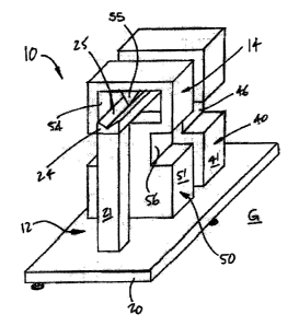
too247 Referring to the drawings, and more particularly
to Fig. l, a level monitoring sensor apparatus is generally
shown at 10. The apparatus 10 generally consists of a
support structure 12 and a sensor mechanism 14. A casing
(not shown) may also be provided in order to conceal the
apparatus 10.
too2s7 The structure 12 has a base 20 from which a pair
of posts 21 project upwardly. The structure 12 stands on a
surface G to be monitored by a plurality of legs 22
(e. g., three legs 22}. The legs 22 are preferably
vertically adjustable (e.g., telescopic legs, bolt-and-nut
legs) so as to level the apparatus 10 with respect to the
horizon, by way of level 23. A support beam 24 extends
horizontally between free ends of the posts 21 and is fixed
thereto. A fixed arm of the support structure 12 is fixed
to the support beam 24.
too2sa The fixed arm 40 has a weight 41 at a free end
thereof, and a finger 42 projecting from the weight 41
towards the balancing arm 50. The finger 42 is best shown
in Fig. 2A and 2B. The finger 42 has in a preferred
configuration a free end 43, and a retaining wall 44 is
provided in a throat portion .of the finger 42. Strain
gauges 45 are positioned on the retaining wall 44 with
opposed gauging surfaces, and are wired so as to measure the
strain that will be sustained by the finger 42, for
instance, at the free end 43.
- & -
too2~~ The sensor mechanism 14 has a balancing arm 50
that hangs from the support beam 24. The balancing arm 50
can pivot about the support ,beam 24. The balancing arm 50
thus moves in a swinging motion, as best shown by arrows A1
and A2 of Fig. 2A. In other words, when contemplating
Fig. 1, the balancing arm 50, if displaced, would come out
of the page. '
Ioo2s) The balancing arm 50 has a weight 51 at a free
end thereof, with an arch 52 connected to a bottom surface
of the weight 51, which will cooperate with the finger 42.
More specifically, the cooperation between the finger 42 and
the arch 52 is shown in greater detail in Fig. 2A. The arch
52 defines an opening 53 in which the free end 43 of the
finger is received. The opening 53 is substantially of the
same size as the thickness of the free end 43 of the finger
42,, such that there is no play therebetween.
too2s~ The apparatus 10 is mounted to a surface whose
level needs to be monitored. The base 20 is positioned so
as to be horizontal with respect to the ground, in which
case the fixed arm 40 and the balancing arm 50 are aligned
with respect to one another, with the arms 40 and 50 being
normal with respect to the horizon. In such a position, the
balancing arm 50 does not exert any pressure on the fixed
arm 40 through the arch 52/finger 42 cooperation. The
apparatus 10 will be subjected to level variations of the
supporting surface G, and this will unbalance the balancing
arm 50, resulting in the balancing arm 50 being normal with
respect to the horizon. A bending of the retaining wall 44
will result from this unbalance, and will be measured by the
strain gauge 45.
Ioosol On the other hand, ~ the fixed arm 40 will not
pivot due to its rigid connection with the support beam 24.
The pivoting of the balancing arm 50 will be transmitted to
the finger 42 by the arch 52 of the balancing arm 50. The
displacement of the balancing arm 50 with respect to the
fixed arm 40 will cause opposing effects of
tension/compression on the opposed gauging surfaces of the
retaining wall 44. This will be picked up by the strain
gauges 45, and the signal will be interpreted as a function
of the level of the element that is measured, to indicate a
level of the surface G of the element being measured.
Circuit configurations for the strain gauges 45 will be
discussed hereinafter.
toosi7 The apparatus 10 , is strategically positioned in
view of level variations of the surface G. For instance, it
is preferred to position the apparatus 10 such that the
plane of rotation of the balancing arm 50 is superposed on
the plane of the level variation of the greatest magnitude.
The sensor apparatus 10 is preferably used to isolate a
level variation in a single orientation of a structure. For
instance, it may be unnecessary to measure the level
variation in every orientation on structures that are
elongated. For instance, a span of a bridge can be equipped
with the sensor apparatus 10 adequately positioned such that
the level variation in a longitudinal dimension of the span,
i.e., from pier to pier, is measured.
Ioo321 The longer the fixed arm 40 and the balancing
arm 50 are, the greater the balancing effect will be
therebetween. Moreover, the weight 51 of the balancing arm
50 accentuates the strain picked up by the strain gauges 45.
On the other hand, the weight 41 stabilizes the fixed
arm 40.
I0033~ It is advantageous to have a single rotational
degree of freedom between the balancing arm 50 and the fixed
arm 40, as this will cause a direction of level variation to
be isolated. The fixed arm 40 and the balancing arm 50 are
preferably identical (i.e., in length and in cross-section),
such that thermal expansion/contraction of the arms 40 and
50 will not have an effect on the strain measurement.
Ioo347 Referring to Fig. 3, a preferred configuration
of the level monitoring sensor apparatus 10 is shown. The
support beam 24 is provided with a trough 25, and the
g
balancing arm 50 defines a channel 54 in which a triangular
cross-section pivot 55 is positioned so as to be received in
the trough 25. The ffixed arm 40 and the balancing arm 50
are shown having a throat portion 46 and 56, respectively,
at a bottom of which weights 41 and 51, respectively, are
located. As mentioned previously, the fixed arm 40 is fixed
to the support beam 24. Alternatively, the balancing arm 50
can be mounted to the support beam 24 by a bearing, as
schematically shown in Fig. 1. The support beam 24 is also
illustrated as being supported by bearings, whereby a
locking system 24' is required to set the support beam 24
once the fixed arm 40 is vertically aligned.
tooss7 The level monitoring sensor apparatus 10 is
designed to monitor the slightest level variation in any
structure standing, hanging, held from one or multiple
corners, held from the center, or resting flat on the
ground. This movement can be caused by various factors such
as time, wind, earthquake, load, supported by the structure,
pressure, landslide, defects in the material of the
structure, loose joints, and poor support or poor
foundation. It is contemplated to set threshold values of
strain sustained by the finger 42 (e. g., at the free
end 43), at which an alarm would sound to indicate
abnormally high level variations. The sensor apparatus 10
can readily be installed on existing structures.
tools) As mentioned previously, the greater the length
of the arms 40 and 50 is, the smaller the level variation
measured can be, as the length of the arms 40 and 50 is
proportional to the strain of the finger 42. It is also
possible to reduce the height arid the width of the retaining
wall 44 so as to increase the signal picked up by the strain
gauges 45. A thinner and shorter retaining wall 44 will be
more sensitive to the pressure exerted by the balancing
arm 50:
too~~~ Referring to the drawings, and more particularly
to Fig. 4A, a solid structure sensor apparatus in accordance
_ g _
with the present invention is generally shown at 100. The
solid structure sensor apparatus 100, hereinafter "sensor
apparatus 100," is shown secured to a solid structure S to
be monitored.
Loo387 The sensor apparatus 100 has a mount portion 102
and a sensor portion 104. The mount portion 102 has a pair
of upstanding posts 120. Each post 120 has at a bottom end
thereof connection ends 121 ~so as. to be fixed to the solid
structure S. The connection ends 121 are illustrated
nonrestrictively as perpendicularly disposed plates used in
combination with bolts 122 to secure the sensor apparatus
100 to the solid structure S. The free end of each post 120
has a horizontal support portion 123, which consists of
perpendicularly disposed flanges. The horizontal support
portions 123 of the posts 120 are separated by a gap 124.
In another embodiment of the sensor apparatus 100,
illustrated in Fig. 4B, a plurality of threaded rods 126 are
welded, inserted, glued or cemented to the solid structure
S, The connection ends 121 are sandwiched between nuts 125,
threadingly engaged with the threaded rods 126, such that
the sensor apparatus 100 can be leveled:
(00397 Referring to Fig. 4A, the sensor portion 104 has
an inverted U-shaped body 140, whose opposed ends sit on the
horizontal support portions 123 of the posts 120. The
sensor portion 104 is fixed to the mount portion 102. The
inverted U-shaped body 140 defines a pair of gauging
surfaces 141 upon which strain gauges 142 are bonded.
Referring to Fig. 5; a preferred positioning of the strain
gauges 142 is shown. One of the two gauging surfaces 141 is
shown in Fig. 5, with the other of the gauging surfaces 141
having a similar strain gauge configuration. Accordingly,
each gauging surface 141 has a pair of strain gauges 142
thereon, with the strain gauges 142 being perpendicularly
disposed with respect to one another., such that one of the
strain gauges 142 of each gauging surface 141 reacts in
compression, while the other one of the strain gauges 142
- 10 -
reacts in tension, or vice. versa. As will be described
hereinafter, the four strain gauges 142 are wired in a
bridge configuration so as to obtain precise strain
measurement of the solid structure S.
too4o7 The posts 120 of the mount portion 102 amplify
bending deformation of the solid structure S. The posts 120
are preferably made of the same material and have a similar
configuration (i.e., length, cross-section, dimension of the
support portions 123), such that thermal changes have
negligible effect on the strain measurement performed by the
sensor apparatus 100. The surface of contact between the
apparatus 100 and the solid structure S is relatively small
to limit friction therebetween for more accurate
measurement.
too~~7 A casing (not shown) is typically provided to
conceal the sensor apparatus 100. The sensor apparatus 100
can be installed on existing structures. The.sensor portion
104 is preferably bolted (but may also be welded thereto) to
the mount portion 102 once the mount portion 102 has been
secured to the solid structure S. The sensor apparatus 100
is designed to monitor the pressure, the strain, the stress,
the overload, the fatigue level, and the strength of any
solid structure. The solid structure S can,be resting on
the ground or can be supported in another way, and may be of
any solid material. Any suitable transducer configuration
can be used for the interpretation of the strain picked up
by the strain gauges.
too427 Referring to the drawings, and more particularly
to Fig. 6, a multicontact pendulum sensor apparatus is
generally shown at 200, and will be referred to .hereinafter
as "sensor apparatus 200." The sensor apparatus 200 has a
mount portion 202 and a sensor mechanism 204.
too437 The mount portion 202 has a casing 220, having
legs 221 by which the sensor apparatus 200 is supported on a
surface S of an element to be monitored. The legs 221 are
adjustable in height and are 'used in combination with a
- 11 -
spherical level 223 on top of the casing 220 to set the
sensor apparatus 200 horizontally. The casing 220 also has
' a compass 224, which will be used to orient the sensor
apparatus 200.
too~47 The casing 220 defines an inner cavity 222
adapted to receive the sensor mechanism 204 therein. The
casing 220 has, for instance, a removable cover so as to
provide access to the inner cavity 222. A support plate 225
is horizontally disposed in the inner cavity 222, and
defines a circular opening 226 by which the sensor mechanism
204 will hang freely in the inner cavity 222. The casing
220 and the support plate 225 of the casing 220 mostly
consist of nonconductive materials.
too45~ The sensor mechanism 204 has a bucket-type
housing 240, having an inner cavity. The housing 240 has a
removable cover 241. The cover 241 has a concentrically
disposed tube 242 with a ball connector 243 at a free end of
the tube 242. The center of the ball connector 243 is
aligned with a center of the.cover 241 and a central axis of
the tube 242. The housing 240 hangs freely in the inner
cavity 222 of the casing 220 by the ball connector 243 being
supported by the support plate 225 and the tube 242 passing
through the opening 226. The cooperation between the
circular opening 226 and the ball connector 243 allows free
movement of the sensor mechanism 204 in three rotational
degrees of freedom with respect to. the mount portion 202.
f004s~ An orientation ring 244 and amplitude rings 245
are supported by nonconductive support arms 258 so as to be
concentrically disposed with respect to the central axis of
the housing 240. This central axis of the housing 240
passes through the center of, the cover 241 and of the ball
connector 243, and is coincident with the axis of the tube
242. The orientation ring 244 is positioned above the
amplitude rings 245. Thereafter, amplitude rings 245A;
245B, 245C and 245D sequentially increase in. diameter from
top to bottom. The orientation ring 244 is connected to a
- 12 -
monitoring board by a plurality of orientation output wires
250. Similarly, each of the amplitude rings 245 has a
respective amplitude output wire 251, so as to be connected
to the monitoring board.
Ioo4z~ A pendulum 247 hangs freely from a center of the
ball connector 243 and passes through each of the rings 244
and 245. The pendulum 247 has a weight 248 at a bottom end
thereof. The wire 246 of the pendulum 247 is conductive,
and is connected to input wire 249 such that an input signal
can be fed to the pendulum 247. Preferably, a liquid is
provided in the housing 240 to dampen movement of the weight
248 of the pendulum 247. Typically, the liquid is a
nonconductive antifreeze oil.'
(oo4e7 As the pendulum 247 hangs freely in the inner
cavity of the housing 240, it is free to swing in any
direction. The amplitude rings 245 are sized such that the
wire 246 of the pendulum 247 comes into contact with the
smaller ring (i.e., 245A) and gradually with the following
ring in diameter. The orientation ring 244 is smaller than
the amplitude rings 245, whereby contact between the wire
246 and the orientation ring 244 will precede or accompany
contact between the wire 246 and any one of the amplitude
rings 245.
Loo49~ Referring to Fig. 7, the orientation ring 244 is
shown consisting of eight annular segments 254. The annular
segments 254 are separated by nonconductive spacers 254'
As shown in Fig. 9, ends of the annular segment 254 overlap
one another. Each of the annular segments 254 is wired such
that, when the wire 246 of the pendulum 247 comes into
contact with one of the annular segments 254 (or two, in the
case of overlapping annular segments 254), current from the
input wire 249 is conducted to the appropriate orientation
output wire 250. Each of the annular segments 254 is given
an orientation such that transmission of current from the
pendulum 247 to the orientation, ring 244 will be identified
as an orientation. Accordingly, a displacement of the
- 13 -
pendulum 247 will have an orientation. It is pointed that,
although the orientation ring 244 is shown having eight
annular segments 254, more or fewer annular segments 254 may
be provided for the orientation ring 244.
too5o~ The increasing diameter of the amplitude rings
245 from top to bottom ensures that the wire 246 of the
pendulum 247 will come into contact with the smallest
amplitude ring, namely amplitude ring 245A. Once more, the
contact between the wire 246 and the amplitude rings form a
loop, whereby the amplitude output wire 251 will send a
signal with regard to the amplitude ring 245 in which
contact has occurred between the pendulum 247 and the
amplitude ring 245.
(oo5y The fluid 252 is provided to reduce unwanted
negligible oscillations of the pendulum 247. Referring to
Fig. 9, a monitoring board to be used in conjunction with
the sensor apparatus 200 is generally shown at 260. The
monitoring board 260 of this embodiment has orientation
indicators 261 and amplitude~indicators 262, and is wired to
the orientation output wires 250 and the amplitude output
wires 251. The orientation indicators 261 are each combined
to one of the annular segments 254 of the orientation ring
244 via the respective orientation output wires 250. The
orientation indicators 261 are combined with orientation
indicia, as illustrated in Fig. 9, to indicate the direction
of the tilting of the element under study. Similarly, the
amplitude indicators 262 are each combined to a respective
amplitude ring 245 to give, e.g., a schematic illustration
of the amplitude. For instance, an amplitude level of 3 may
indicate a warning of strong amplitudes, whereas an
amplitude level of 4 can trigger an alarm.
Ioo52~ The sensor apparatus 200 must be calibrated in
order to match the orientation of the respective annular
segments 254 with the actual cardinal points. A cardinal
point indicator 255 (e. g., north) is provided on the housing
240 such that the housing 240 can be rotated to match the
- 14 -
actual orientation provided by the compass 224. The ball
connector 243/circular opening 226 configuration enables
rotation of the sensor mechanism 204 in accordance with the
appropriate orientation. A weight 256 ensures that the
sensor mechanism 204 is aligned vertically prior to the
orientation. The weight 256 may be removed thereafter for
normal operation of the sensor apparatus 200. A fixing
mechanism 257 is also used to prevent movement between the
sensor mechanism 204 and the mount portion 202, once the
orientation is set and the sensor mechanism 204 is
vertically positioned. Accordingly, the pendulum 247 will
be the only movable portion of the sensor apparatus 200,
whereby level variation of the surface S can be qualified in
magnitude and orientation.
toos3~ The sensor apparatus 200 can be used to indicate
the tilting progress of structures against time, wind,
earthquake; loads, landslide, defects in material, and weak
support or foundation. The longer the wire of the pendulum
247 is, the more sensitive the apparatus will be to small
degrees of tilting. Similarly, the smaller the amplitude
rings 245 are, the more sensitive the sensor apparatus 200
will be to small degrees of inclination. Obviously, more or
fewer amplitude rings 245 can be, provided.
too54~ The sensor apparatuses 10, 100 and 200 can be
used individually or simultaneously in a plurality of
structures. More particularly, but not exclusively,
bridges, tunnels, dams, earthquake detection systems,
landslide detection systems, silos, tanks., reservoirs,
roofs, railways, subways, foundations, floors, walls,
nuclear plants, industrial chimneys, high-rise buildings and
towers, industrial signs, cranes, high-rise posts for cable
carts, power lines and amusement parks, and involve the
sensor apparatuses of the present invention.
Loo55~ For instance, Fig. lOA illustrates a bridge B.
The level monitoring sensor apparatuses 10 are installed on
the spans of the bridge, along with the solid structure
n
- 15 -
sensor apparatus 100, to monitor any unusual activity
(e.g., level and deflection) of the bridge B. The
multicontact pendulum sensor apparatuses 200 are installed
in the piers P to monitor the tilt.
foo5s~ The group of sensor apparatuses 10, 100 and 200
on the bridge B can be powered by solar energy. A solar
panel is shown at 302. A control station positioned
remotely from the bridge B can receive sensor apparatus data
through a communication system such as wireless
communication antenna 304. A monitoring board 300 is
illustrated in Fig. lOB, and can be provided as an intensity
indicator to indicate to a bridge traffic operator whether
the bridge B can be used.
(oos~1 For instance, each of the sensors 10, 100 and
200 installed on the bridge B can be connected to three
lights on the monitoring board 300, with a red light
indicating hazardous unusual activity, that could prompt the
operator to close the bridge B.
Loo5s~ It is within the ambit of the present invention
to cover any obvious modifications of the embodiments
described herein; provided such modifications fall within
the scope of the appended claims.