Note: Descriptions are shown in the official language in which they were submitted.
x
CA 02423417 2003-03-25
t
-1-
System and Method for Metering Electricity Supplied to a Customer
Field of the invention
The invention relates to metering electricity supplied to a customer.
Background of the invention
Utility companies provide electricity to many customers in both rural
and urban settings. The electricity provided is generated at a generating
plant, and transmitted via transmission lines that span large geographic
areas.
To minimize power toss associated with the internal resistance of the
transmission lines; so-called ohmic loss, the voltage of the electricity is
typically increased or "stepped-up" near the generating plant before being
transmitted via the transmission lines. Transmission line voltages can vary
from 600V to 500,OOOV, with a typical voltage near a residential site being
about 4,OOOV to 8,OOOV. Before being delivered to the customer, this high,
potentially dangerous voltage is decreased or "stepped-down" with a step-
down transformer.
Besides the delivery of electricity, an important component of the utility
company involves accurately metering the amount of electrical energy
supplied to a consumer to later bill them therefor. The meter for this purpose
is located near the customer. For residential customers, the meter is
typically
adjacent to an outside wall of the house of the customer to which electricity
is
y
CA 02423417 2003-03-25
r
-2-
supplied. Unfortunately; the fact that the meter is located on the premises of
the customer, allows unscrupulous customers to tamper with the meter. For
example, by boring a hole in the ground to access a frost loop, which is a
coil
of conductor for accommodating weather extremes, the customer can bypass
the meter and avoid being charged for electricity use. This problem is
widespread enough to cause large monetary losses for utility companies.
It is an object of the present invention to mitigate the problem of meter
tampering.
Summary of the invention
in accordance with the present invention, a system and method are
provided for metering the electricity supplied to a customer that circumvent
the aforementioned problems associated with losses that arise because of
meter tampering. The meter is disposed near the step-down transformer
where it cannot be by-passed by the customer. For example, the meter can
be affixed to a surface of the transformer unit. The utility has secure means
to
prevent access to the transformer.
In particular, a system is described herein for metering electricity
supplied to a customer. The system includes a source of electricity at a
primary voltage, and a transformer unit for decreasing the primary voltage of
t
CA 02423417 2003-03-25
i i
-3-
the electricity before supplying the electricity at a decreased voltage to the
customer. The system further includes a metering apparatus for metering the
electricity supplied to the customer. The metering apparatus contains a
metering control unit that includes at least one of a) a processor for
determining an amount of electrical energy supplied to the customer, b) a
datalogger for storing data that is indicative of the amount of electrical
energy
supplied to the customer, c) a display for displaying the amount of electrical
energy supplied to the customer, and d) a communication link for transmitting
the data to a remote site. The metering control unit is disposed near the
transformer unit. In particular, the distance from the metering control unit
to
the transformer unit is less than forty-two centimeters.
Such a distance affords various installation options. In particular, forty-
two centimeters is long enough to permit other hardware, such as wiring, to
be installed between the transformer unit and the metering control device.
This distance is also short enough to be able to use some of the existing
components at the transformer site for metering, such as the concrete support
of the transformer unit to afFix the metering control unit, or a locked
enclosure
to restrict access to the metering control unit.
CA 02423417 2003-03-25
-4-
Brief description of the drawings
Figure 1 shows a block diagram of a transformer-metering system for
metering electricity supplied to a customer, according to the teachings of the
present invention.
Figure 2 shows the transformer unit of the transformer-metering system
of Fig. 1.
Figure 3 shows the metering apparatus of the transformer-metering
system of Figure 1.
Figure 4 shows a profile of the transformer-metering system of Figure
1.
Figure 5 shows a line diagram of the transformer-metering system of
Figure 1.
Figure 6 is a flowchart for metering electricity supplied to a customer,
according to the teachings of the present invention.
i P
CA 02423417 2003-03-25
7
-5-
Detailed descriution of the invention
The electricity provided by utility companies is generated at a
generating plant, and transmitted via transmission lines that span large
geographic areas. To minimize power loss associated with the internal
resistance of the transmission lines, so-called ohmic loss, the voltage of the
electricity is typically increased or "stepped-up" near the generating plant
before being transmitted via the transmission lines. A typical transmission
voltage at the residential level can be about about 8000V. Before being
delivered to the customer, this high, potentially dangerous voltage is
decreased or "stepped-down" with a step-down transformer. The stepped-
down voltage that is delivered to a customer is metered to determine the cost
to be incurred by the customer.
In accordance with the present invention, the metering apparatus is
installed near the transformer, which prevents the customer from tampering
with the meter. Installing the meter near the transformer also saves costs by
avoiding duplication of hardware. For example, the transformer site usually
already includes supports that can be used to install the meter, as well as
security components, such as padlocks to restrict access to authorized
personnel. Additionally, installing the meter near a high-voltage transformer
can act as a deterrent to someone thinking of breaching the enclosure
containing the transformer and meter.
r t
CA 02423417 2003-03-25
r ,
-6-
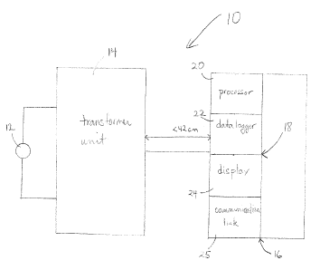
Figure 1 shows a block diagram of a transformer-metering system 10
for metering electricity supplied to a customer, according to the teachings of
the present invention. The transformer-metering system 10 includes a source
of electricity 12 at a primary voltage, a transformer unit 14, and a metering
apparatus 16 that contains a metering control unit 18. The metering control
unit 18 includes at least one of a processor 20, a datalogger 22, a display 24
and a communication link 25. The distance from the metering control unit 18
to the transformer unit 14 is less than forty-two centimeters.
The source of electricity 12 can be a conductor connected to a
transmission line used to transmit electricity from a generating site, as
known
to those of ordinary skill. The primary voltage at which electricity is
transmitted is typically large, e.g., 4000V-27,600V, to minimize ohmic losses.
Before the electricity is provided to the customer, the primary voltage is
reduced. The transformer unit 14 decreases the primary voltage of the
electricity before supplying the electricity at a decreased voltage to the
customer.
The metering apparatus 16 meters the electricity supplied to the
customer with the metering control unit 18. The metering control unit 18
includes at least one of a processor 20 for determining an amount of
electrical
energy supplied to the customer, a datalogger 22 for storing data that is
indicative of the amount of electrical energy supplied to the customer; a
f
CA 02423417 2003-03-25
6
- -
display 24 for displaying the amount of electrical energy supplied to the
customer, and a communication link 25 for transmitting the data, which is
indicative of the amount of electrical energy supplied to the customer, to a
remote site. For example, the communication link 25 can be connected to a
computer network that can be accessed by the utility company to download
the data. Alternatively, or in addition, the data can automatically be
downloaded at predetermined intervals to the utility company via the
communication link 25.
Figure 2 shows the transformer unit 14 of the transformer-metering
system 10 of Fig. 1. The transformer unit 14 includes a step-down module 26
that contains a primary coil 28 and a secondary coil 30. The transformer unit
14 also includes a support 32.
The step-down module 26 reduces or "steps-down" the primary
voltage. In particular, the primary coil 28 is a conductor that is wound NP
times around a core, such as an iron core. Electricity at the primary voltage,
in the form of an alternating current; flows through the primary coil. The
second coil 30 is also a conductor that winds around the core NS times, with
NS < NP. As predicted by Faraday's Law of Induction, a voltage is induced in
the secondary coil, which is less than the primary voltage because N~ < NP.
The induced voltage results in an alternating current in the secondary coil.
CA 02423417 2003-03-25
-
Thus, electricity at the reduced voltage flows in the secondary coil before
being supplied to the customer. Typically, the reduced voltage is greater than
or equal to about 120V and less than or equal to about 240 V.
The transformer unit 14 includes a support 32 for supporting the step-
down module 26. For example, the support 32 can include a concrete vault
that is partially buried below ground level 36. Alternatively, the support 32
can
be of a pedestal type; the support 32 can also be constructed from fiberglass
or plastic. In one embodiment, the metering control unit 18 is affixed to the
support with bolts. Alternatively, the metering control unit 18 can be affixed
to
the transformer unit 14 of a different location, such as the outer surface of
the
step-down module 26.
Figure 3 shows the metering apparatus 16 of the transformer-metering
system 10 of Figure 1. The metering apparatus 16 includes a sensor 38, and,
as described above, a metering control unit 18 that includes at least one of a
processor 20, a datalogger 22, a display 24 and a communication link 25.
The metering control unit 18 may further include a potential fuse 40 and a
relay 42. The sensor 38 is connected to the metering control unit 18 by a
metering conductor 44.
CA 02423417 2003-03-25
_g_
The sensor 38 produces an electrical signal for determining the amount
of electrical energy supplied to the customer. The sensor 38, for example,
can include at least one of a current transformer, a potential transformer and
a
watt transformer. The electrical signal is transmitted to the metering control
unit 18 via the metering conductor 44. Once the signal reaches the metering
control unit 18, the processor 20 therein can determine the amount of
electrical energy supplied to the customer.
The datalogger 22, which has recording means 46 to write or delete
data, and/or a databank 48, stores data indicative of the amount of electrical
energy supplied to the customer. The display 24 can display this amount so
that it may be read by power personnel and/or the customer. The
communication link 25 can be used to transmit the data to a remote site. For
example, the communication link 25 can be connected to a computer network
that can be accessed by the utility company to download the data.
Alternatively, or in addition, the data can automatically be downloaded at
predetermined intervals to a server of the utility company via the
communication link 25. Optionally, the server can be accessed by the
customer, provided the customer has a password that allows access to the
data.
The potential fuse 40 protects the metering apparatus 16 from a short
circuit or overload, and the relay 42 is used to remotely switch a particular
t
CA 02423417 2003-03-25
-10-
load on and off. For example, the relay can include an electrical switch that
is
remotely controlled by the injection of a coded signal into the electrical
network. For example, the relay 42 can permit the utility company to switch
water heating on and off at set times.
Figure 4 shows a profile of the transformer-metering system 10 of
Figure 1. The transformer-metering system 10 includes the step-down
module 26, the metering control unit 18, the sensors 38 and the metering
conductors 44. The transformer-metering system 10 also includes duct banks
50 and internal conduits 52.
The duct banks 50 and internal conduits 52 serve as pathways for
inserting wiring necessary to carry the electricity to various customers and
to
link the transformer site to the phone company. Such a link allows meter data
to be accessed using telephone lines. The metering control unit 18 is
disposed in the area where the support 32 (e.g., a concrete vault) and the
step-down module 26 meet, and can be bolted to either or both. By placing
the metering control unit 18 near the transformer unit 14, instead of near the
residence of the customer, tampering with the metering of electricity is more
difficult. In fact, as access to the transformer unit 14 is typically
restricted to
only utility personnel with a locked cabinet or other enclosure, the
transformer
unit 14 and the metering control unit 18 are well-protected from tampering.
CA 02423417 2003-03-25
-11-
The sensor 38 can be a device that produces an electrical signal
suitable for determining the amount of electrical energy supplied to the
customer. For example, a current, potential or watt AC transformer (or
transducer) running at an amperage of 0-5 A and voltage of 120-240V, and
accepting a variety of AC waveform inputs can be used. These transformers
typically have an accuracy of better than 2% for watt transducers and 1 % for
potential and current transducers, and a current output capable of supplying
up to 10 or 20 mA in low-impedance metering. These transformers can have
their own built-in power supplies that operate on either 120 VAC or 240 VAC.
The signal from the sensor 38 is processed by the processor 20 of the
metering control unit 18. The processor 20 can employ various types of
metering, such as time-of-use metering and static metering. In time-of-use
metering, electrical energy that is measured is recorded discreetly by the
datalogger 22 for an interval of time, such as each minute. The intervals are
stored electronically along with the date and time of energy usage. These are
retrieved electronically via the communication link 25 at a later date.
In static metering, the energy that is measured is recorded on a
cumulative register display 24, or a digital LCD display 24, in contrast to
time-
of-use metering, where the energy is recorded and the meter zeroed
periodically, such as every minute. Static metering may be done with single
CA 02423417 2003-03-25
-12-
displays, such that any energy consumed on a site is shown on the display.
The display 24 allows a customer to physically see the meter read. To take a
reading for a particular month off of the static meter, the previous months
read
is subtracted from the current read.
Metering data on the dataloggers can be accessed by one of several
methods, such as telephone (including cell phone), landline and visually.
Metering data can be downloaded via a cell phone: The landline may be a
telephone line, a computer network line or a fibre optic line, such as links
the
Internet.
The metering data can be downloaded to a utility company server via
the communication link 25, which may then be accessed by the customer
using a computer network or telephone line. The metering data may also be
read visually from the display 24. In particular, a customer can arrange to
read the display 24 at the site of the transformer unit 14 with the assistance
of
utility personnel.
Figure 5 shows a line diagram 54 for the transformer-metering system
of Figure 1. Electricity at the primary voltage 12 can arrive at the primary
coil 28 via a utility underground system. Elbows 53 allow a proper connection
between the source 12 and the primary coil 28. The voltage at the primary
coil is typically 800OV. The primary coil 28 induces a current in the
secondary
CA 02423417 2003-03-25
-13-
coil 30 of reduced voltage. With the one step-down module 26 containing the
coils 28 and 30, at least twelve hou es or residential customers (service
numbers 1-12) can be served. 1n some cases, twenty to thirty customers can
be served. The current transformer sensors 38 can produce an electrical
signal that can be used by the processor 20 to meter the electricity supplied
to
the homes.
Figure 6 is a flowchart for metering electricity supplied to a customer.
In step 60, the metering control unit 18 is installed within forty-two
centimeters
of the transformer unit 14. In step 62, electricity is provided at the primary
voltage. In step 64, the primary voltage of the electricity is decreased with
the
transformer unit 14. In step 66, electricity is supplied at a decreased
voltage
to the customer, and, in step 68, metered with the metering control apparatus
18.
It should be understood that various modifications and adaptations
could be made to the embodiments described and illustrated herein, without
departing from the present invention. For example, although emphasis has
been placed on describing a transformer-metering system 10 having a
metering control unit 18 affixed to the support 32, it is possible to dispose
the
system anywhere within forty-two centimeters of the transformer unit 14. The
scope of the invention is defined by the following claims.