Note: Descriptions are shown in the official language in which they were submitted.
CA 02423472 2006-12-14
METHOD AND PLATE APPARATUS FOR DEW POINT
EVAPORATIVE COOLER
BACKGROUND OF THE INVENTION
1. Field of the Invention. The invention relates to the field of
= 5 evaporative fluid conditioning. More specifically, the invention relates
to the field of sensible cooling of fluids (gas, liquid or mixtures with
and without phase changes) to substantially the dew point for gas by
indirect evaporative cooling within a heat exchanger having canalized
gas and fluid flows and a lateral temperature gradient across the heat
exchange plates.
2. Discussion of the Backsiround. Indirect evaporative cooling
is a method of cooling a gas stream, usually air, by evaporating a
cooling liquid, usually water, into a second air stream while
transferring heat from the first air stream to the second. The method
has certain inherent advantages compared to conventional air
conditioning: low electricity requirements, relatively high reliability, and
the ability to do away with the need for refrigerants such as R-134 and
all the disadvantages they entail. However, indirect evaporative
cooling is as yet only used in specially built commercial applications,
and is not yet available on the market as a residential or after market
product. This is due to certain disadvantages of known indirect
evaporative coolers and methods: excessive cost, ineffective
thermodynamic cycle that does not allow for enough cooling of air for
{E5255756.DOC;1}
CA 02423472 2006-12-14
-2-
the expenses involved, ineffective water supply system, scale buildup,
poor or expensive heat exchanger, excessive pressure drop, difficulty
approaching the dew point of the air stream (the theoretical limit of
cooling), relatively high dew points in humid atmospheres, large
pressure drops across the heat exchange apparatus, large heat
exchange apparatus, and in some designs, reliance on a good deal of
ancillary equipment.
US Patent No. 4,002,040 issued to Munters et al on Jan. 11,
1977 discloses a heat exchanger in which there is no mixing between
canalized air streams, and in which the air stream passing through the
device is put through a 270 degree turn within the device, resulting in
a large pressure drop engendered by the flow path. Additionally,
Munters does not allow for cooling fluids other than outside air and
cannot be used in applications where recirculation is desired.
US Patent No. 5,187,946 issued to Rotenberg et al on Feb. 23,
1993, discloses a heat exchanger having perforations through the
heat exchange plates and alternating wet and dry channels. The
applicant herein disputes the validity of the U.S. patent as it was
based on applicant's Russian patent and disclosed more than a year
before the US patent was filed, as well as the Rotenberg patent is
invalid as it copied the Russian patent, yet does not disclose the
earlier patent or the true inventor, V. Maisotsenko. The present
invention is different in substantial ways from the 5,187,946 disclosure
(Maisotsenko Russian Patent 2046257) does not use a separate
treatment of product fluids (cooled fluids, whether gas, as 5,187,946's
disclosure is limited to, or other fluids), the thin plastic plates that
operate as efficient heat transfer from dry channels to wet channels
yet do not transfer heat laterally along the surface or the plates, or a
shallow slope to the heat exchange plates to allow efficient wicking
{E5255756.DOC;1}
CA 02423472 2006-12-14
-3-
action, but instead discloses a relatively high angle. It also does not
reveal use of a feeder wick, instead using complex and costly spray
heads located in each wet channel. Finally, 5,187,946 argues against
the use of channel guides, urging that turbulent flow provides better
efficiency. However, this does not allow 5,187,946 to control the
lateral temperature profile of the individual heat exchange plates. In
addition by separating the working air stream from the product the
working air decreases in flow as it passes through the channel
perforations, reducing its pressure drop and at the same time allowing
better control of the exhaust channels. This patent, similar to Munters
above is limited to cooling outside air.
US Patent No. 5,170,633 issued to Kaplan on Dec. 15, 1992,
shows the amount of ancillary equipment which can proliferate in
indirect evaporative systems. US Patent Nos., 5,727,394, 5,758,508,
5,860,284, 5,890,372, 6,003,327, 6,018,953, 6,050,100, issued to
Belding et al and Goland et al, display the same syndrome of
excessive air treatment equipment. In examining systems such as
those referred to, it should be borne in mind that a single additional
heat exchanger adds more than one third to the overall cost of the
system. These systems, aside from the different methods again only
apply for cooling air.
US Patent No. 5,453,223, dated Sept. 26 1995, and nominally
issued to the present applicant, discloses an apparatus in which
alternating sets of wet and dry plates provide two streams of air: one
dry, cooled by contact with the plates beside it, and one wet, cooled
by direct evaporation. However, the unit requires two gas flows in and
two gas flows out. In addition, the design in question does not provide
for indirect cooling only, without additional direct evaporative cooling.
While such a second stage of direct evaporative cooling, raising the
{E5255756. DOC;1 }
CA 02423472 2008-12-18
. =
-4-
humidity of the product air, is often desirable, it is as often not
desirable.
Two pending applications by the present inventor also address
the technology of indirect evaporative cooling. WO/2001/057460,
filed February 7, 2001, discloses one method of eliminating a second
stage of direct evaporative cooling. WO/2001/057459 filed on
February 7, 2001, discloses better methods of design of the heat
exchange cores of indirect evaporative coolers, allowing better wetting
and reduced pressure drops.
An indirect evaporative method and apparatus providing more
efficient air flow dnd heat transfer is desirable.
CA 02423472 2006-12-14
-5-
SUMMARY OF THE INVENTION
The present invention provides an indirect evaporative cooler
of fluids of all types having cross flowing wet and dry channels on
opposite sides of a heat exchange plate which allows heat transfer
through the plate due to thin plastic construction or other suitable
materials but prevents or minimizes heat transfer laterally along the
plate. For purposes of application, we wish to define certain terms:
1. Heat transfer surface or heat exchange surface has
many configurations. All are encompassed within the subject of this
disclosed invention with appropriate adjustment to the wetting and
flows as are well known in the industry. For the example of the
illustration we make use of a plate configuration.
2. Wet side or portion of the heat exchange surface means
that portion having evaporative liquid on or in its surface, thus
enabling evaporative cooling of the surface and the absorption of
latent heat from the surface.
3. Dry side or portion of the heat exchanger means that
portion of the heat exchanger surface where there is no evaporation
into the adjacent gas or fluid. Thus, there is no transfer of vapor and
latent heat into adjacent gases. In fact, the surface may be wet but
not with evaporative fluid or wet by condensation, but no evaporation
exists.
4. Working stream or working gas stream is the gas flow
that flows along the heat exchange surface on the dry side through
the dry working channels, passes through the passages in the surface
to the wet side through the wet working channels and picks up vapor
and by evaporation takes latent heat from the heat exchange surface
and transports it out into the exhaust. In some embodiments, the
{E5255756.DOC;1}
CA 02423472 2006-12-14
-6-
working stream may be disposed of as waste and in others it may be
used for special purposes, such as adding humidity or scavenging
heat.
5. Product stream or product fluid stream is the fluid (gas,
liquid or mixture) flow that passes along the heat exchange surface on
the dry side through the dry product channels and is cooled by the
absorption of heat by the working gas stream on the wet side
absorbing latent heat by the evaporation in the wet area.
The plate also has passageways or perforations or transfer
means between the dry side of the plate and the wet side in defined
areas providing flow from the dry working channels to the working wet
channels in which direct evaporative cooling takes place. By means
of the perforations the working gas streams have a pressure drop
through the system, which is reduced.
The method of the invention makes use of the separation of a
working gas flow (that is used to evaporate liquid in the wet channels
and thus to cool the wet surface of the heat exchanger plate) from the
product fluid flow, both flowing through dry product channels and dry
working channels on the same side of the heat exchange plate and
that both give up heat to the heat exchange plate that on its obverse
surface is being cooled by evaporation in the working wet channels.
The working gas flow first enters the dry working channel and
then through perforations, pores or other suitable means of transfer
across the barrier of the plate to the wet side and thence into the wet
working channels where evaporation of liquid on the wet channel
surface, cools this plate.
The dry product channels are on the dry side of this plate. The
plate is of a thin material to allow easy heat transfer across this pate
and thus to readily allow heat to transfer from the dry product channel
{E5255756. DOC;1 }
CA 02423472 2006-12-14
-7-
to the wet working channel. This is one basic unit or element of the
invention illustrating the method of the separation of working gas flows
to indirectly cool the separate product fluid by evaporative cooling.
It is therefore on object of the invention to provide an indirect
evaporative cooler having perforations allowing flow from dry working
channels to wet working channels on the opposite side of the heat
exchange plate.
It is another object of the invention to provide an indirect
evaporative cooler having heat exchange plates, which do not allow
substantial lateral heat transfer but do allow heat exchange through
and across the plate. This produces a temperature transfer across
the plate that is not averaged out by lateral heat transfer down the
plate. Averaging the temperature down the plate would effectively
reduce the temperature difference through and across the plate and
results in lower heat transfer rates across the plate. Thus, it is part of
this invention to have heat readily transfer across the plate from the
dry side to the wet side but not readily transfer along the surface of
the plate.
It is another object of the invention to provide an indirect
evaporative cooler having a temperature gradient across the two
dimensional surface of the plate, and thus providing working gas
stream channels having a range of temperatures.
It is another object of the invention to provide an indirect
evaporative cooler allowing selection of the product fluid streams for
use in cooling, in particular, the fluid streams exiting from the coldest
product channels may be selected for use in cooling. Conversely, the
selection may be of some portion of the working gas streams to give
added humidity to the environment.
{E5255756.DOC;1}
CA 02423472 2006-12-14
-8-
It is another object of the invention to provide an indirect
evaporative cooler having efficient wicking action allowing easy
wetting of substantially all of the surface area of the wet channels with
out excess water that cools the water rather then the air.
It is another object of the invention to provide an indirect
evaporative cooler having feeder wicks providing water uniformly to all
wet channels of the device.
It is yet another object of the invention to provide an indirect
evaporative cooler having cycle selection means, so that during
summer months, it may be used to provide cooled, non-humidified air,
and during winter months, it may be used to scavenge heat from
gases exiting a space while simultaneously humidifying the space.
It is yet another object of the invention to provide an efficient
indirect evaporative cooler, allowing cooling of a stream of a product
to substantially the working gas dew point temperature.
It is another object of the invention to provide an efficient
indirect evaporative cooler having a relatively small pressure drop for
working gas streams.
{E5255756. DOC;1 }
CA 02423472 2006-12-14
-9-
BRIEF DESCRIPTION OF THE DRAWINGS
Figure 1(a) is a three dimensional perspective and schematic
representation of a first embodiment of the invention method, showing
the gas flow path of the working gas for cooling of the gas in passing
through a perforation or passage from a dry side of a plate to a wet
side of the plate. The dry side of the plate has separators to keep the
working gas path separate from the product fluid path.
Figure 1(b) is a perspective and schematic representation of
the obverse side of Figure 1(a) showing the wet side with channels
and depicting the working gas flow after it goes through the passages
and then along the wet surface of the channels where evaporation
occurs.
Figure 1(c) is a perspective and schematic representation of
two plates, such as in Figure 1(a) and 1(b) showing the wet side
channels formed by the wet sides of a first and a second plate
opposing each other, with their passages oriented in the same
general area and illustrating the working gas entering on the dry side,
passing through the passages and into the wet side channels. The
product fluid is separated from the working gas as they pass along the
dry side of the first and second plates. Additional plates would have
adjacent plates having their dry side oppose the dry sides of these
first and second plates. Thus, the stack of plates would have every
odd plate oriented with its dry side facing the same direction and
opposite of all even plates.
Figure 1(d) is a three dimensional perspective and schematic
representation of a second embodiment of this aspect of the
invention, showing a working gas flow path from the segregated
working dry path entering the wet side by perforations or passages
{E5255756. DOC;1 }
CA 02423472 2006-12-14
-10-
and exiting one side of the plate after passing across the wet surface
of the wet surface of the wet working channel.
Figure 2 is a three dimensional perspective and schematic
representation of a third embodiment of this aspect of the invention,
showing the gas flow path when the invention is used to warm and
humidify an air stream.
Figure 3 is a partially three dimensional perspective and
schematic representation of the flow path of a fourth embodiment of
this aspect of the invention showing the working gas flow when the
invention is used for cooling of a dehumidified product fluid, and
further showing the product fluid flow in the context of use.
Figure 4 is a partially three dimensional perspective and
schematic representation of the flow path of a fifth embodiment of this
aspect of the invention showing working and product gas flow when
the invention is used with recirculating gas flow, and further showing
the gas flow in the context of use.
Figure 5 is a three dimensional perspective and schematic
representation of an expanded assembly of multiple channels,
showing dry side flow, additional perforations, and additional channel
guides with the perforations predominately in the middle of the
membrane. The dry working gas enters and passes through the
passages to the wet side (not shown).
Figure 6 is a three dimensional perspective and schematic
representation of the same expanded assembly of Figure 5, showing
wet side gas flow after the dry working gas passed through the
passages. The surface of the plate has wicking material to carry liquid
from the feeder wick method to the edges of the plate and to supply
the liquid for evaporation cooling.
{E5255756.DOC;1 }
CA 02423472 2006-12-14
-11-
Figure 7 is a cross-sectional view of the assembly of Figure 5
with additional plates, showing gas flow with the side wings being
angled upward from the mid point. The plate on top has its dry
surface. The bottom of this plate is wet and the channel guides
orthogonal to the dry side channels. The second plate has its wet
surface facing the first plate's wet surfaces making the channels
between the first and the second plate wet. The second plate has its
dry surface on the bottom. Successive plates continue to match dry
to dry surface, and wet and to wet surfaces.
Figure 8 is a perspective view of a two sided core with a feeder
wick plate between the two sides and the upward angled wings
orientation of the core layers from the center.
Figure 9 is a partially exploded perspective view of an
assembly of the invention, including schematic representations of gas
flow and fluid flow with upward angled wings of a core.
Figure 10 is a partially exploded perspective view of an
embodiment of the invention using a plate such as Figure 1(d) with
the liquid supplied to the wick material on the plates by a reservoir.
There would be successive plates with dry dry and wet wet surfaces.
Figure 11 is a perspective view of a two part core with a center
feeder wick plate between the two wings with the wings angled
downward from the center and perforations in area of each layer
nearest the center wick.
Figure 12 is an embodiment of the feeder wick plate used in
Figure 8 with grooves that run some or all of the way from the highest
to the lowest point to speed liquid transfer to the bottom of the wick
and to allow excess liquid to be drained.
Figure 13 is a second embodiment of the feeder wick plate with
hole through the inner part of the feeder wick plate.
{E5255756.DOC;1}
CA 02423472 2006-12-14
-12-
Figure 14 is a third embodiment of a feeder wick plate
comprised of a sandwich to aid quick distribution of liquid to the outer
perimeters of the feeder wick plate and to aid drainage. The
sandwich is comprised of materials with two different porosities the
middle layer having greater porosity than the outer layer.
Figure 15 is a perspective view of two cores similar to Figure 8
with the air pathways shown and illustrating a separation gap between
the two cores to aid in heat transfer rates by breaking up the paths
into segments and thus break up large pathways which create
boundary layers which in turn inhibit heat transfer.
Figure 16 is an assembly of a reservoir piping and valving in
conjunction with a feeder wick plate usable in assembly such as figure
8, 15 and other embodiments. The upper reservoir feeds the feeder
wick plate. The lower reservoir by way of a float valve determines if
the wick is short of liquid and thus having a lower reservoir level in the
bottom reservoir, which then turns on the feeder valve to supply more
liquid to the top reservoir.
Figure 17 shows the reservoir system of Figure 16 incorporated
with the core assembly of Figure 8.
{E5255756. DOC;1 }
CA 02423472 2006-12-14
-13-
DETAILED DESCRIPTION OF THE INVENTION
Figure 1 a is a three dimensional perspective and schematic
representation of a primary element of the invention demonstrating
the method by which indirect cooling occurs. The element is formed
as a flat plate (and thus also referred to herein as plate 6), includes
perforations 11 which connect dry side 9 to wet side 10. Dry side 9 is
further subdivided and segregated into product channels 3 and
working gas dry channel 4: perforations 11 are within working gas
channel 4. Wet side 10, see figure 1 b, is wetted with an evaporative
liquid to provide cooling. Wet side 10 also has wet channel 5. Dry
channels 3 and 4, figure 1 a, are segregated so the working dry gas is
kept separate from the dry product fluid. Channel guides 8 define dry
channels 3 and 4 by preventing intermixing of the gas between the
channels 3 and 4 and relatively freely transfer across plate 6 from the
perpendicular gas streams on the other side. As the plate 6 is very
thin, heat may readily pass perpendicular through and across this
plate from the dry side to the wet side. The plate material is selected
to minimize heat transfer along the plate. A preferred material is
plastic. The materials of the channel guides aside from providing
barriers to define channels may also advantageously insulate the
streams as much as possible from the adjacent parallel streams on
both sides, thus offering a low rate of "parallel heat transfer".
In use, a product stream of fluid 1 and a working stream of gas
2 are respectively drawn into dry channels 3 and 4, traversing the dry
side of plate 6 in a laminar flow. Working gas stream 2 then flows
through perforations 11 to the wet side 10 and into channels 5. Wet
channels 5 on the wet side directs gas stream 2 in a direction
substantially perpendicular to the fluids flowing on the dry side and
{E5255756.DOC;1}
CA 02423472 2006-12-14
-14-
across the wet side 10 of plate 6, where it receives heat in several
ways: first, in the form of evaporation of liquid from wet side 10 and
second, as heat rejected by conduction and radiation from plate 6.
Thus plate 6 acts as a heat exchanger and as an indirect evaporative
cooler. Gas flow 2 emerges from the indirect evaporative cooler 6 as
gas streams 2, as indicated in Figure 1(a) and Figure 1(b).
The cross flow need not be exactly perpendicular, as long as
the flow is "substantially perpendicular". At 180 degrees, the flow
becomes a counter flow, and at 0 degrees, the streams on both sides
of plate 6 may be parallel. A substantially perpendicular flow may
occur at an angle between these two extremes, provided the angle
allows the streams on opposite sides of the plate to cross each other.
The importance of having the streams on opposite sides of plate 6 is
that this provides a temperature gradient and temperature differential
discussed later.
In this embodiment all of working gas stream 2 passes over the
center of the plate 6 in dry channel 4. On the obverse side of plate 6,
under dry channel 4, gas stream 2 is in contact with the wet side and
is cooled by evaporation. At the inlet, stream 2 (on the dry side in
channel 4) is being cooled by the evaporation on the obverse side of
plate 6. This acts as precooling of stream 2. Thus as stream 2
proceeds down channel 4 on the dry side before entering perforations
11, it's dry cooled to ideally the wet bulb temperature. This precooling
in the dry side, allows this stream to enter the wet side cooler than its
original temperature therefore with a continuing lower wet bulb
temperature.
The canalization of the gas streams 1 and 2 further increases
the efficiency of the device by allowing control of the flow within it and
control of temperature. The temperature differential through and
{E5255756. DOC;1 }
CA 02423472 2006-12-14
-15-
across the plate 6 is generated by the flow of gas stream 2 through
the wet channels 5; at the start of the flow of gas stream 2 through the
wet channels 5, it is very dry and can absorb the maximum of vapor
from the evaporative fluid.. This in turn absorbs the maximum amount
of latent heat (transition from liquid to vapor), which in turn allows for
the greater temperature differential through the plate 6. Thus channel
3 nearest the channel 4 will be cooled the most.
In practice the product fluid may be any fluid (air, gas liquid or
mixed) for which dry cooling is desired, that is, cooling without addition
of a partial pressure gas component derived from evaporation of the
cooling liquid. For example, in commercial and residential usage, the
fluid may be air and the cooling liquid water: the product air streams
that emerge from the dry side channels invention do so without having
any humidity added. It can be refrigerants, either during phase
changes or not, to allow for cooling to lower temperatures before use
and thus achieve greater efficiencies in the refrigerant cycle at low
cost.
In the embodiment pictured, in Figure 1, the segregation of the
working dry gas 2 from the product fluid 1 may be by channel guides 8
that act as walls between adjacent plates. In the end of dry channel
4, a barrier or wall 12 prevents the working dry gas from exiting and
mixing with the product fluid. If plate 6 is corrugated, the channel
guides are partially provided by the corrugations in the plate itself.
The channel guides would be present on either or both sides of plate
6 and between the product fluid and working gas to prevent passing of
fluids between the corrugations of the opposite plate. In either case,
they function to channel the gas or fluid streams, and may also
advantageously maintain the separation of plate 6 with other plates, in
those embodiments having more than one heat transfer plate. In
{E5255756.DOC;1 }
CA 02423472 2006-12-14
-16-
addition corrugated channel guides may be used in between flat
plates 6, in which case no additional separation is needed.
Wet side 10 of plate 6 may advantageously include a wick layer
material capable of transpiring the cooling liquid across wet side 10.
Preferably, the wick layer may cover substantially the entire surface
area of wet side 10. The wick layer may comprise any of a number of
well known materials: cellulose, organic fibers, organic-based fibers,
porous plastics, carbon-based fibers, polyesters, polypropylene,
fiberglass, silicon-based fibers and combinations of these substances.
The wick layer material may be in a number of forms: films, weaves,
braids, beds of particles such as beads and combinations thereof.
Advantageously, the wick layer material may be the material of
plate 6. For example, plate 6 may be a wick layer material treated on
one side to make it impermeable, the impermeable side then being
used as the dry side of plate 6. The treatment may consist of
changing the nature of the wick layer material itself, or coating it with
another substance such as a plastic film or equivalent. The wick layer
material may be treated to be of low permeability instead of being
entirely impermeable. In this application, "low permeability' means
that the amount of water allowed through plate 6 to dry side 9 is small
enough that the gas streams crossing dry side 9 do not become
substantially humidified and are not substantially cooled by
evaporation. Substitution of a low permeability dry side for an
impermeable dry side nonetheless allows practice of the invention as
claimed herein.
Alternatively, the material of plate 6 may be impermeable and
treated to render it permeable or to wick on the wet side 10. In either
case, the material of plate 6 should have a relatively high resistance
to heat transfer. While this has almost no effect on heat transfer
{E5255756.DOC;1}
CA 02423472 2006-12-14
-17-
through plate 6, because it is thin, heat cannot be transferred laterally
across the plate, as discussed earlier.
Plate 6 may also receive its cooling liquid from a feeder wick,
as will be discussed below in reference to other embodiments.
Perforations 11 may advantageously be round or other shapes
having no corners, or shapes such as polygons with rounded corners
not only to increase the durability of the plates but also in order to
help prevent turbulence in gas stream 2 as it is passing there through.
By preventing turbulence, the pressure drop across the indirect
evaporative cooler may be minimized, with corresponding increases in
efficiency of operation and reduction in construction costs. The
perforations may be passages, such as micro pores, rather than
perforation.
Plate 6 may advantageously slope so as to prevent
accumulation of excess water, and/or to allow a lower edge of plate 6
to sit in contact with a supply of the cooling liquid, such as a water
reservoir, whereby the wicking material may act to keep wet side 10
supplied with cooling liquid. By keeping the slope quite low, from
approximately -10 degrees to approximately +10 degrees, the
transpiration of liquid across wet side 10 is rendered much more
efficient. At greater angles of slope, the maximum wicking height of
the wicking material unduly limits the width of the plates. In extreme
cases, transpiration may be rendered inefficient or impossible, thus
reducing the amount of evaporative cooling achieved due to an
inadequate supply of cooling liquid to evaporate. Depending on the
nature of the wick layer material, the wick may not transport liquid to
the entire wet side 10, leaving some areas dry, or it may leave some
sections surface dry but without enough liquid for efficient evaporation
to create high levels of relative humidity in the working gas stream.
{E5255756.DOC;1 }
CA 02423472 2006-12-14
-18-
Thus a low angle provides considerably more efficient wicking, and for
a given maximum wicking height, allows greater width.
Plate 6 may also have a double-sloped "V" cross-section as is
illustrated in Figure 6 and Figure 7, that is, plate 6 may in cross-
section resemble a shallow valley with a median section lower than
two opposing edges or wings. The two slopes may be of different
lengths or angles of slope, or may differ in nature of wick layer
material or other factors.
Plate 6 may also be equipped with a "stream selection damper"
(not shown), allowing selection of only the coldest gas streams from
the dry side of plate 6 (i.e. those also it may include damper to select
some humid working gas to add humidity to the environment to the
center of the plates), or all of the gas streams, or some intermediate
selection. By allowing only the coldest streams to be used for cooling,
a smaller but colder gas flow is provided; use of a larger selection of
the gas streams provides a larger gas flow. Also the damper may
select humid working gas for use in humidifying an environment.
Figure 1 a is a three dimensional perspective and schematic
representation of a second embodiment of the element of the
invention. In this embodiment, plate 6 has perforations 11 along one
side rather than down the middle, as in the previous embodiment.
Channel guides 8 create dry channels 3 and 4. In this embodiment,
channel guides 8 are ribs, but they may be other types of guides, as
previously discussed. Channel guide 8 also serves to prevent flow of
gases off of one edge of plate 6. Working gas stream 2 flows in
channel 4, product stream 1 flows in channel 3. Gas stream 2, the
working gas, flows through perforations 11 to channel 5 (not visible),
and then flows across the obverse side of plate 6 to depart plate 6 as
gas stream 2.
{E5255756.DOC;1}
CA 02423472 2006-12-14
-19-
Figure 2 is a three dimensional perspective and schematic
representation of a third embodiment of the invention, showing the
gas flow path when the invention is used to warm and humidify an air
stream with water. Thus, in this embodiment and those following, the
gas steams may be referred to as air streams, and the cooling liquid
will be assumed to be water. In winter months, it is advantageous to
exchange heat between exhaust air leaving a warmed space and cold
fresh air being brought in from the atmosphere, i.e. the out door air or
other source of environmental air. This reduces the heat required to
warm the fresh air. The present invention also allows the addition of
humidity to the fresh air, thus addressing another winter problem: cold
outside air that has condensed moisture out and therefore has a low
absolute humidity or extremely dry air that results in dry inside air as
the moisture on the inside reduces with fresh air changes with the
outside. The "cycle selection" as to which stream of air is exhausted
to the atmosphere, and which goes to the space to be conditioned, is
a feature of embodiments having this arrangement.
In Figure 2, Plate 6 has dry side 9, wet side 10, channel guides
8, and perforations 11. Air steam 1 exits the conditioned space as air
streams. Meanwhile, fresh air 2 enters and flows through perforation
11. As in the two previous embodiments have shown, plate 6 acts as
a heat exchanger to remove heat by conduction from air stream 1, on
dry side 9. On wet side 10, air stream 2 flows through channels on
the wet side (not visible) and other parallel channels, receiving both
heat (via conduction and radiation) and humidity (via evaporation)
from wet side 10. Wet side 10 may have a wick material, as
discussed previously, and the construction of plate 6 regarding
permeability, materials, treatments, feeder wicks, channel guides,
corrugations, perforations, stream selection dampers, etc, may also
{E5255756, DOC;1 }
CA 02423472 2006-12-14
-20-
be as previously discussed. In this manner, energy already used to
heat air stream is conserved while humidity is added to the fresh air
stream 2.
A "cycle selection damper" (not shown) provides the ability to
switch between the cooling cycle and the warming/humidification
cycle. At the simplest, the cycle selection damper may simply be
used to select which stream of air is passed to the space to be
conditioned: the air which passes only across the dry side 9 or the air
which passes across both dry side 9 and wet side 10. The damper
may also provide different sources for the air streams 1 and 2, as will
be obvious to those skilled in the art.
Figure 3 is a partially three dimensional perspective and
schematic representation of the flow path of an embodiment of the
invention in an assembly showing the gas flow when the invention is
used for cooling, and further showing the gas stream in the context of
use. In this embodiment, one gas stream is air from a conditioned
space. Since that air frequently emerges from the conditioned space
cooler and dryer than outside air or cooler than desiccated air, it can
profitably be used as the working stream in the evaporative cooler of
the invention.
Indirect evaporative cooler plate 6 comprises channel guides, a
plurality of perforations (collectively numbered 11 for convenience).
Dry product air stream 1 is provided by a desiccation wheel 25 and
enters channels 3 on the dry side. Flowing across plate 6 on the dry
side, it transfers heat to plate 6, emerging cooler but without added
humidity. Air emerges from conditioned space 24 as working air
stream 2, which flows into indirect evaporative cooler plate 6 in
channel 4, where it again transfers some heat to plate 6 by
conduction before it passes through perforations 11 into the channel
{E5255756.DOC;1 }
CA 02423472 2006-12-14
-21-
on the wet side. On the wet side of plate 6, air stream 2 is cooled by
evaporation and simultaneously cools plate 6 by the same action,
before being expelled as air streams 2.
Desiccant wheel 25 may contain a liquid or solid desiccant of
known type. The desiccant within desiccant wheel 25 must be
recharged, that is, must have the water it has absorbed from air
stream 1 removed. This is accomplished by reactivation air 27, which
flows through air heater 26 before entering desiccant wheel 25. The
high temperature of reactivation air 27 removes from the desiccant
humidity absorbed from air stream 1. An additional heat exchanger
may be used to transfer heat from air stream 1, after it has been
heated and dried by flowing through desiccant wheel 25, to
reactivation air 27, before air heater 26 heats it, this technique is
known in the art. However, it will be appreciated that neither the
present embodiment nor the presently preferred embodiments
described below use such an additional heat exchanger, as the
present invention provides highly efficient cooling to near dew point
temperatures, while the additional heat exchanger adds over 45
percent to the cost of the overall system.
Figure 4 is a partially three dimensional perspective and
schematic representation of the flow path of a fifth embodiment of the
invention showing the gas flow when the invention is used with
recirculating gas steams, and further showing the gas flow in the
context of use. In this embodiment of the invention, air from a
conditioned space is cooled again and returned as the product fluid.
This results in a saving of energy and additional cooling of the product
air stream.
Plate 6 has channel guides, channels, and a plurality of
perforations collectively numbered 11. Air stream 1 emerges from
{E5255756. DOC;1 }
CA 02423472 2006-12-14
-22-
desiccant wheel 25 before passing over the dry side of plate 6 in
channels, where it transfers heat to plate 6 by conduction. Air stream
1 is then passed to conditioned space 24 and eventually recirculated
to desiccant wheel 25.
Channel guides segregate working air stream 2 from product
air stream 1 after desiccant wheel 25. It passes through channel,
where it rejects heat to plate 6 and flows through perforations 11 to
the wet side of the plate. As in previous embodiments, wet channel is
not visible, but arrows indicating working air streams show that there
may be a plurality of wet side channels. At this time, working air
streams 2 absorb heat from plate 6 by evaporation, radiation and
conduction, cooling plate 6.
Figures 5 and 6 are three dimensional perspective and
schematic representations of a large plate containing the elements of
the invention, showing dry side gas flow, wet side gas flow, through
channels not shown but present on the obverse side, additional
perforations, and additional channel guides, while figure 7 is a cross-
sectional view of figure 5, showing gas flow on the wet side.
Evaporative cooler has product gas streams, working gas
streams, product channels, working channels, wet side channels, wick
material, channel guides, dry side, wet side, perforations, block, and
feeder wick holes.
In use, working gas or product fluid streams respectively flow
into dry channels 4 and 3, transferring heat to the heat exchanger
without increase in humidity. Working gas stream flows through
perforations into wet side channels 5. Figures 6 and 7 show that
evaporative cooler comprises a plurality of plates (the three diagrams
respectively show one, two and three plates, but the number of plates
is not limited to this range). The plates may be "identical" in the sense
{E5255756. DOC;1 }
CA 02423472 2006-12-14
-23-
of having channels on both sides cooperating with perforations 11 to
allow gas streams to flow through the plates, being composed of
materials having a poor lateral heat transfer rate and being
impermeable on one side, with dry sides opposing each other across
the plate spacing and wet sides opposing. The plates of the invention
may also be dimensioned and configured to embody the invention
without being identical. The plates are aligned in parallel and have
like sides facing. In this application, "like sides facing" refers to the
fact that wet sides face the wet sides of other plates while dry sides
face other plates. It does not refer to the placement of perforations
11, which will be discussed further below.
In wet side channels, air stream receives heat from the plates
of evaporative cooler 6 by the mechanisms previously described.
Also as noted earlier, working gas stream 2 is itself pre-cooled by its
passage across the dry side of the plates of the evaporative cooler 6
in channel 4, resulting in further cooling action by the device of the
invention. Further as noted earlier, the gas streams may be selected
based upon heat rejection (coolness) for service either as product or
working air or with or without humidity. Thus, block 12 (see Figure 8)
seals the end of channels 4, requiring all of air stream 2 to flow
through perforations 11 to the wet side channels. Under different
conditions, some of air stream 2 may be allowed to leave the end of
channel 4 by removal of block 12, resulting in a greater volume of
slightly less cool product air, or in the alternative, some of air stream 1
may be diverted or blocked (that portion of air stream 1 which was
furthest from the center of evaporative cooler 6 and thus received the
least cooling), thus producing a smaller quantity of slightly cooler
product air. Other alternatives for the construction of the invention are
also as described earlier.
{E5255756. DOC;1 }
CA 02423472 2006-12-14
-24-
Thus, air streams in this assembly flow between two plates
rather than across one plate. If two such plates are aligned with dry
sides facing, then the air streams flow between the two plates on the
dry sides, if the wet sides are facing, the air streams flow between the
plates on the wet sides. In embodiments having more than two
plates, air streams will first flow between the dry sides of two plates,
then will flow through one or both plates and enter wet channels, in
which they will flow across one of the two previous plates (on the
reverse side) and the wet side of a third plate.
Feeder wicks 13 may pass through feeder wick holes in order
to supply water to wick material 7, and will be discussed with
reference to figures 8 and 9.
Figure 9 are partially exploded perspective view of a seventh
and preferred embodiment of the invention, including schematic
representations of gas flow, as viewed from two different angles.
Indirect evaporative cooler 14 is built up in approximately a box
shape, although this shape may be optimized to suit conditions, as is
well known in the art. A plurality of plates 6 forms the stack. Each of
plates 6 has a wet side 10 and a dry side 9, although for the sake of
clarity these are referenced for only the topmost plate 6. Plates 6 are
aligned in parallel and oriented with like sides facing, so wet sides 10
face wet sides 10 and dry sides 9 face other dry sides 9.
It is advantageous to provide plates 6 in which perforations 11
do not line up directly facing the perforations in adjacent plates.
Instead, in the preferred embodiments of the invention, perforations
11 are offset from the perforations 11 in the next plate 6. This helps
to reduce the pressure drop across the evaporative cooler 14, thus
reducing the energy required by the device and increasing efficiency.
{E5255756, DOC;1 }
CA 02423472 2006-12-14
-25-
In addition this creates better distribution of air in the wet evaporative
channel 5.
Cooler 19 also has water reservoir 17, pump 15, and feeder
wicks 13. Water is removed from water reservoir 17 by pump 15 and
lifted to feeder wicks 13. A reservoir refill line 8 allows water reservoir
17 to be continuously refilled or refilled as desired.
Although spacing of the plates (the dry and wet channels) may
be any amount for some gases or fluids, spacing of plates 6 is
important to efficient use of the invention. If the spacing is properly
selected, pressure drop of the gas streams passing through the
invention is greatly reduced, providing either greater flow or the ability
to use smaller or fewer fans or blowers. Experiment has shown that
an inter-planer spacing of 1.5 to 3.5 millimeters is preferable, and
spacing within the sub-ranges of 1.50 to 1.85 millimeters, 2.00 to 2.35
millimeters, 2.10 and 2.90 millimeters and 3.10 and 3.50 millimeters is
more preferable. Without being bound by any particular theories, it is
believed that at these spacings, standing waves are set up which
reduce drag during the flow processes. It is also possible that at
these spacings, turbulent, non-laminar flow is discouraged, which may
also serve to reduce drag and pressure drop in this particular process.
The proper spacing may be maintained by separate structural
elements (not shown) or may advantageously be provided by the
channel guides 8, which may be provided ribs or corrugations of plate
6, or by other means.
Feeder wicks 13 comprise tubes having a wick material
covering at least a portion of the outside of the tube. Holes through
the tube allow water within the tube to reach and wet the exterior wick
material, which is in contact with the wick material 7 on wet sides 10.
Water flows out through the holes into the exterior wick material.
(E5255756. DOC;1)
CA 02423472 2006-12-14
-26-
From there it, may transpire from the wick material of the feeder wick
to the wick material 7 of wet sides 10 and so across such portion of
wet side 10 as is covered by wick material 7.
Product fluid stream 1 enters dry channels 3, while working air
stream 2 enters dry channels 4, both on the dry sides 10 of plates 6.
Working air stream passes through perforations 11 into wet side
channels 5, functioning as previously described cooling plates 6.
Note that for the sake of clarity, only four working air streams are
shown exiting the cooler 14 and only one entering it, but there may be
any number, and they may (and in this preferred embodiment do) exit
from both sides of cooler 14.
Channel guides serve several functions. In addition to
separating air streams 1 and 2, they act to subdivide air streams 1
and 2 further, thus creating better temperature distribution in the
invention, creating channels having cooler product air 1 near the
center of plates 6, help to insure standing wave flow or laminar flow,
thus reducing the pressure drop across the device, and help to
insulate the parallel subdivisions of air streams 1 and 2, thus
preventing parallel heat transfer. Finally, channel guides 8 also serve
as structural members to support the stack and separate plates 6 by
the desired distance.
Block 12 (visible in Figures 8 and 9) prevents working air 2
from leaving the device via dry channels 4, thus forcing it to flow
through wet channels 5. Stated differently, the outlet for wet channels
5 will always be downstream of the perforations. As stated previously,
in alternative embodiments, some product air may also be
blocked/diverted or some working air allowed to leave as product air in
accordance with requirements and conditions.
{E5255756.DOC;1 }
CA 02423472 2006-12-14
-27-
As previously discussed, the amount of pre-cooling which
working air stream 2 undergoes, is in part determined by proper
selection of perforations and channel sizing. Also as discussed
previously, the material of plate 6 provides poor lateral heat transfer,
thus in turn providing a temperature differential or gradient laterally
across plate 6. Channel selection dampers (not shown) may
advantageously be used to select which of the subdivisions of air
streams 1 and/or 2 are used for conditioning, thus allowing a greater
degree of cooling than otherwise, as well as providing for flexible
control of the output gas temperature, humidity and quantity.
Fans or equivalent blower devices are schematically
represented as 19 and 20, but the invention is subject to alternative
embodiments of the fan arrangement. For example, one fan as
forced draft may be used to provide both working and product air
streams 1 and 2. In addition, a forced draft fan has advantages over
an induced draft. Due to the evaporative process used by the device,
the parasitic heat added by the fan motor to airstreams 1 and 2 is
efficiently used to further evaporate water and thus the heat aids in its
own removal, resulting in little difference to the temperature of final
product air stream 1. A forced draft fan provides air to both the
working air and product air channels according to the pressure drop
through each and any outside dampers that may be used. Finally,
since the working and product air emerge at different outlets, two fans
are required to induce two drafts, while only one fan is required to
force both drafts.
Stack 14 may be enclosed in a housing (not shown), which
housing may further direct and control airflow, as well as enhancing
the esthetics of the device. The housing may comprise inlets and
outlets for the product and working air streams, and a damper to allow
{E5255756. DOC;1 }
CA 02423472 2006-12-14
-28-
the direction of airflow to be controlled. For example, when the
damper is in a first position, it may cause the cooler to operate
normally, whereas when the damper is in a second position, it may
cause the warmed, humidified working air to become the product air.
This may be used in conjunction with recirculating air, as described
above, to provide humidification and pre-warming of winter air.
As in previous embodiments, the indirect evaporative cooler 14
may be used in conjunction with recirculating air streams, desiccant
wheels, corrugated plates, and treatment of the material of the plates,
perforations and other details.
Note that the indirect evaporative cooler of the invention may
also accomplish both direct and indirect evaporative cooling of the
product air stream 1. A portion of the dry sides 9 may be wetted, in a
manner similar to the wick materials used on wet sides 10 or in a
different manner, so as to cause further cooling of the product air
stream. This wet portion of the dry sides may advantageously be
placed downstream of the dry portion of the dry sides, so that prior to
being humidified in the direct evaporation cooling process, the
sensible temperature of the product air stream 1 is reduced as much
as possible. One particular advantage of this ordering is that below
approximately 65 degrees F, modest increases in humidity cause
disproportionate reduction in air temperatures, in accordance with
standard psychometric charts. In another preferred embodiment of
the invention, this wetted portion of the dry sides constitutes the final
1 to 25 percent of the surface area of the dry channels 3.
Figure 10 is a three dimensional perspective and schematic
representation of an eighth embodiment of the invention, showing gas
flow and a reservoir of water.
{E5255756.DOC;1}
CA 02423472 2006-12-14
-29-
Evaporative cooler 6 has dry sides 9 , wet sides 10, product air
stream 1 and working air stream 2, channel guides 8, dry channels 3
and 4 and wet channels 5, as well as water reservoir 17. In this
embodiment, there is no need for a water pump or feeder wicks
because the wick material of wet sides 10 is directly placed in water
reservoir 17. However, the width of the plates of cooler 6 is limited to
the maximum wicking height of the wicking material unless the plates
are sloped, as described earlier, which slope also allows more
efficient wicking. This embodiment is also an example of an indirect
evaporative cooler of the invention, which uses exhaust from only one
side of the plates.
In Figure 8, the two wings of the cores extend out and upward
from the center. In the center, as depicted is a feeder wick plate that
communicates liquid used for the evaporative cooling in the wet
channels to the wick material layers of the core.
In Figure 8, the wings are angled upward, between
approximately 0 degrees and +10 degrees. An alternate is illustrated
in Figure 12, where the wings are angled downward from the center,
also within the approximate range of slope of 0 degrees to -10
degrees.
The selection of upward or downward sloping wings will also
include a selection of wick material in the wet surfaces of the layers,
so that the liquid migrates over the entire surface of the wick material
surface of each plate.
The advantage of the downward slope is that the liquid will
more readily reach the edges due to the added impetus of gravity.
This will aid in the reduction in the scale build up on the edges that
can occur with liquids that have mineral content.
{E5255756.DOC;1 }
CA 02423472 2006-12-14
-30-
The added assistance of gravity (or downward sloping wings) is
that it allows more length of the wings to be wetted from the center
feeder wick and it will be accomplished faster.
The potential of excess water being collected at the outer
edges of the wings in a downward sloping core, is that liquid droplets
will form. Also when excess liquid is being cooled, unnecessary
cooling of the liquid diminishes the efficiency of the evaporative
cooler. To minimize the excess water, the wicking material on the
layers will be less porous than the feeder wick.
The upward angled wings, Figure 8, will not have the excess
water collecting at the edges of the layers. The more likely issue is
not enough water reached the outer edges, resulting in lost cooling
potential and the build up of minerals at the dry edges.
The embodiments of the feeder wick plates 13, shown in
Figures 13, 14 and 15, are refinements of a solid feeder wick plate.
The purpose of the channels or grooves 50, Figure 13, the holes 51,
Figure 14, or the sandwich 52, Figure 15, all are to enable quicker
movement of liquid from the top, where liquid is introduced to the
feeder wick plate, to the bottom and thus more quickly wet the core
wick material. Alternate methods to accomplish the distribution aid
may include rods 57 placed along the sides of the feeder wick (see
Figure 12).
The channels, holes and more porous core of these
embodiments will allow liquid to move throughout the feeder wick
plate and, thus, aid distribution of the evaporative liquid.
The channels, holes or cores may not extend all of the way to
the bottom of the feeder wick plate, as this would allow the liquid to
too easily pass through these passageways before wetting the feeder
wick.
{E5255756. DOC;1 }
CA 02423472 2006-12-14
-31-
Figure 15 illustrates a set of core sections with a gap 55
between adjacent sections. This gap performs a function of breaking
up the canalized air streams into discrete segments. This in turn
reduces the build up of boundary layers in the channels, which
prevents efficient heat transfer. Where the channels are small or the
velocity is low, the fluid tends to be in laminar flow. In the boundary
layer next to the plate in the dry channels the heat transfer rate is
lower. This boundary layer is nil at the entrance of the plate and grows
to some steady state amount with in the first few inches. Therefore
the heat transfer rate is significantly greater at the entrance to any
channel and reduces exponentially to some smaller steady state
amount.
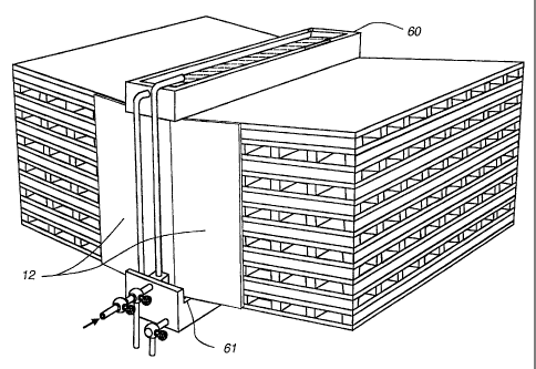
An embodiment of the reservoir system is shown in Figure 16
and in Figure 17 in conjunction with the cores and feeder wick plates.
The top reservoir 60 feeds liquid to the feeder wick plate. The
top reservoir is fed by a valve and piping with the appropriate liquid.
As the reservoir feeds the feeder wick, excess liquid passes to the
lower reservoir 61.
A float valve 62 relies upon the level in the lower reservoir to
activate the supply valve 63 for the upper reservoir.
As the wick takes liquid to the wick material on the layers of the
core, the upper reservoir 60 is depleted. If there is more evaporate
than excess liquid draining into the lower reservoir 61, the float 62 will
be lower. As it gets lower it activates the supply valve 63 to add more
liquid to the upper reservoir 60.
As there becomes an excess of liquid fed to the feeder wick
plate 13, more than can evaporate, the excess collects in the bottom
reservoir 61, which raised the float and in turn cuts off the supply
valve to the upper reservoir. This system does require a continual
{E5255756.DOC;1}
CA 02423472 2006-12-14
-32-
bleeding off of water from the bottom reservoir such that it can sense
the water entering the system. This bleed drain also helps to prevent
mineral concentration.
In this way the evaporation rate determines the need to add or
diminish the liquid to the feeder wick core.
Added features would include an over flow drain 64, cold turn
off and drain system 65. A Thermostat may activate the supply of
liquid to the reservoir in any commonly arranged systems.
The use of plastic, cellulose or other pliable materials may not
be suitable for the heat transfer membranes in some applications
where refrigerates or steam are condensed with pressures and
indirect cooling. The channels for the product fluid may need to be a
metal such as aluminum or other suitable stiff and walled structures,
such as tubes with the walls being the heat exchange surface.
By pre-condensing and cooling refrigerates, with indirect
cooling in cores such as the disclosed invention, efficiencies of less
pressure are needed to compress the gaseous refrigerant during its
cycles can save heat build up and power usage.
The use of cores as disclosed is more efficient and less costly
than cooling tower and as such, capable of by incorporation into
residential systems.
The invention and the embodiments described herein are
susceptible to many equivalents, alterations and additions without
departing from the scope of the invention. This description in no way
limits that scope, which is determined by the following claims.
{E5255756. DOC;1 }