Language selection

Search

Patent 2423707 Summary

Third-party information liability

Some of the information on this Web page has been provided by external sources. The Government of Canada is not responsible for the accuracy, reliability or currency of the information supplied by external sources. Users wishing to rely upon this information should consult directly with the source of the information. Content provided by external sources is not subject to official languages, privacy and accessibility requirements.

Claims and Abstract availability

Any discrepancies in the text and image of the Claims and Abstract are due to differing posting times. Text of the Claims and Abstract are posted:

  • At the time the application is open to public inspection;
  • At the time of issue of the patent (grant).
(12) Patent Application: (11) CA 2423707
(54) English Title: PLANT SUPPORT J HOOK
(54) French Title: CROCHET EN J POUR TUTEUR
Status: Dead
Bibliographic Data
(51) International Patent Classification (IPC):
  • A01G 9/12 (2006.01)
(72) Inventors :
  • MASTRONARDI, ESTER (Canada)
(73) Owners :
  • MASTRONARDI, ESTER (Canada)
(71) Applicants :
  • MASTRONARDI, EASTER (Canada)
  • MASTRONARDI, ESTER (Canada)
(74) Agent: FINLAYSON & SINGLEHURST
(74) Associate agent:
(45) Issued:
(22) Filed Date: 2003-03-27
(41) Open to Public Inspection: 2003-09-27
Availability of licence: N/A
(25) Language of filing: English

Patent Cooperation Treaty (PCT): No

(30) Application Priority Data:
Application No. Country/Territory Date
60/368,031 United States of America 2002-03-27

Abstracts

English Abstract


Disclosed is a clip for supporting a plant comprising a hook portion to engage
a plant structure, a body portion including a grip structure, a twisting
portion attached
to the body portion, and a clip portion attached to the twisting portion
including legs
having an edge portion formed from a mold parting line.


Claims

Note: Claims are shown in the official language in which they were submitted.


CLAIMS

What is claimed is:
1. A clip for supporting a plant comprising
a hook portion to engage a plant structure;
a body portion including a grip structure;
a twisting portion attached to the body portion; and
a clip portion attached to the twisting portion including legs having an edge
portion formed from a mold parting line.

2. A device for supporting a plant comprising:
a unitary body of polymeric material including an elongated shaft terminating
at
one end in a U-shaped hook for attachment to said plant and terminating at the
other end
in a cup for attachment to a string-like support,
said shaft having a first cross-sectional area in a fast region adjacent said
U-
shaped hook and having a second cross-sectional area in a second region
adjacent said
clip, said second section cross-sectional area being smaller than said first
cross-sectional
area whereby twisting of said shaft is facilitated in said second region,
a radially extending flat grip member unitary with said first region far
facilitating
manual manipulation including twisting of said cup relative to said hook,
said clip comprising a body portion unitary with said shaft and having a cam
surface extending at an inclination angle relative to said shaft from said
second region,
a pair of leg members disposed on opposite sides of said body portion with
each
leg member extending from the free end of said body member toward said one end
of


said shaft terminating in a free end, each leg member being substantially
parallel to said
shaft, said leg members lying in a common plane with said hook and said grip
member,
each of said leg members defining a ramp surface extending from its free end
at
an angle convergent with said cam surface, said ramp surface terminating in a
detent
notch for capturing said string-like support between said body portion and
said leg
member,
whereby said clip may be secured to said string like support by forcing said
string-like support between said ramp surface and said cam surface.

-5-~

Description

Note: Descriptions are shown in the official language in which they were submitted.


CA 02423707 2003-03-27
PLANT' SIJPPOR~'" J H "00~
This invention relates to a plain support device and Specifically to a plant
support
l hook to secure a limb of a plant to a support structure
Typically in agricultural production support structures are used to increase
yield
by supporting the plant and prevem branches from kinking A Irinkizig branch
will
restrict flow of water and nutrients to fruit or vegetables growing from tbte
plant. A
weighted down branch tanks to prevent nutrients from Mowing to the vegetable
of fruit.
Typically, a support is used to prevent ranches of a plant froru kirlldug.
(3ne type of support structure iuclades a string or wire extending vertically
and
parallel relative to the plant. Support clips dre attached to the support
structure and the
Plat to support the weight of the fruit or vegetables born by the plant
Agricultural operations are labor intensive and the installation of support
clips to
each individual plarn is time consuming sud expensive. Installation of plastic
clips to
support structures requires workers to revisit each plant during growth to
install
additional clips to support the plant.
for these reasons it is desirable to pmvide a support clip that is easy to
install in
order to expedite installation. Further, many plants ate disposed of after
harvest.
Removal of support clips frorrr each plant before disposal is inefficient and
costly-
Therefore, ii is desirable that a support clip be iriexpettsive such that
disposal and
repurchase of the support clip is economically feasible relative to the cost
of removing
the clips from a harvested plant.
BRIEF DESCRIPTION OF THE DRAWINGS
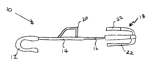
Figure 1 is a top view of the plant support J hook according to the invention.
Figure 2 is a side view thereof.
Figure 3 is an enlarged view of the clip portion as seen in Figure 1.
Referring to Figures i-3, the support clip of this invention is a I book 10
including
a book portion I2 attached to a sltaR 14. Ozi the shaft 14 is a grip ~0. The
grip ZO
provides a grasp point on the 3 hook I4 for installation to the plant. A clip
portion I S
attaches the J hook 10 to a support strucatre. The clip 18 is secured to the
shaft 14 by
way of a shaft I6 of a smaller diameter. The small diameter of the shaft 1 b
allows for the
hook l 2 to twist relative to the cup 18. louring installation, tire clip 18
may not be
assembled to the support suucture in a way that provides for optimum alignment
and
connection to the plant. Therefore, the smaller diameter shaft portion 16
allows for the
hook I2 to twist relative to the clip 18 to accommodate varying alignrr:euis
of the plant.

CA 02423707 2003-03-27
Further, twisting of the book 12 relative to the clip 18 allows for the
installation onia
many sterns ar branches resardless of the position of the support structure.
The clip 18 includes a body portion 26 and a leg portion 22. E$ch leg portion
22
extends parallel to the body portion 26. each leg portion 22 includes a catch
pardon 24.
In operation, the catch portion 24 traps the support wire or string aver
guiding over the
leg 22. The atrir~ or support wire is then trapped between the catch portion
24 and the
bottom of the body portion 26. This configuration allows for guick assembly to
a support
to expedite installation of the 3 hook i0 to a pleat. The 3 hook 10 of this
invention
provides the grip 20 on a side opposite that Qf hook 12. This configuration
accommodates assembly to the plants because the operator's hand is not an
obstacle to
iastallat;on to the plant.
A great concern ixt the manufacture of the 3 hook 10 of this intention is
cost. Cost
of the 1 hook 10 must be such that it is economically feasible to dispo$e of
the J hook 10
with the plant after the fruit or vegetable is harvested from the plant. Xt is
for this reason
that unique molding techniques have been incorporated into production of the
.r hook 10.
A parting line 30 is astir to farm the sharp poim or edge of 28 of each Ieg
22. The edge
28 assists in installation of the 3 hook IO by providing an easy catch of the
wire or
support line by an operator grasping the J !took at the grip 2Q. Supporting
line 30 farms
the tip ar edge 28 of each leg 22.
In operation, the worker grasps the J hook 1Q by the grip 20. The string or
support wire guides along the bottom portion of the body 26 in a direction
indicated by
32. The wire or support string guides upward along the Ieg 22 and into the
catch portion
?4. The catch portion 24 is substantially parallel to the body potrion 26 such
that a
desired amount of tension is exerted on to the wire or support string to
prevent the ~ hook
from sliding downward along the support wire or string. As appreciated it is
desired
for a 3 hook 10 to remain on the support in the location assembled, while also
being
easily movable along the support. The catch portion 24 is parallel to the
bottom body
portion 26 such that the clip l0 remains in place slang the support.
Preferably, tb~e Ciip 10 is fab~cated from a copolymer polypropylene that
includes an uluaviolet stabilizer. As appreciated the environment iri w#tich
the t hook l0
is installed includes a great deal of uliravialet light. For this reason,
degradation of the 3
-2-

CA 02423707 2003-03-27
hook caused by the ultraviolet light is addressed by the specific use of
material.
Although preferably a copolymer polypropylene is used with this J hook clip it
is with the
contempt$tion of this invention that other materialx tray be used that $re
Compatible with
use and exposure to ultraviolet radiation
1'he foregoing description is exemplary anti trot just to the tttaterial
specification.
The invention has been described in an illustrative maauer, arid should be
underxtood the
terminology used is inrended to be in a nature of description rather than of
limitation.
Many modifications and variations of the present invention are possible in
lil;ht of the
above teachings. The preferred embodiments of this invetnion have been
disclosed,
however, one of ordinary skill in the art would recognize that certain
modifacations are
within the scope of this invention.
-3-

Representative Drawing
A single figure which represents the drawing illustrating the invention.
Administrative Status

For a clearer understanding of the status of the application/patent presented on this page, the site Disclaimer , as well as the definitions for Patent , Administrative Status , Maintenance Fee  and Payment History  should be consulted.

Administrative Status

Title Date
Forecasted Issue Date Unavailable
(22) Filed 2003-03-27
(41) Open to Public Inspection 2003-09-27
Dead Application 2009-03-27

Abandonment History

Abandonment Date Reason Reinstatement Date
2006-03-27 FAILURE TO PAY APPLICATION MAINTENANCE FEE 2007-02-01
2008-03-27 FAILURE TO REQUEST EXAMINATION
2008-03-27 FAILURE TO PAY APPLICATION MAINTENANCE FEE

Payment History

Fee Type Anniversary Year Due Date Amount Paid Paid Date
Application Fee $150.00 2003-03-27
Maintenance Fee - Application - New Act 2 2005-03-28 $50.00 2005-03-07
Reinstatement: Failure to Pay Application Maintenance Fees $200.00 2007-02-01
Expired 2019 - Corrective payment/Section 78.6 $200.00 2007-02-01
Maintenance Fee - Application - New Act 3 2006-03-27 $100.00 2007-02-01
Maintenance Fee - Application - New Act 4 2007-03-27 $100.00 2007-03-05
Owners on Record

Note: Records showing the ownership history in alphabetical order.

Current Owners on Record
MASTRONARDI, ESTER
Past Owners on Record
None
Past Owners that do not appear in the "Owners on Record" listing will appear in other documentation within the application.
Documents

To view selected files, please enter reCAPTCHA code :


To view images, click a link in the Document Description column. To download the documents, select one or more checkboxes in the first column and then click the "Download Selected in PDF format (Zip Archive)" or the "Download Selected as Single PDF" button.

List of published and non-published patent-specific documents on the CPD .

If you have any difficulty accessing content, you can call the Client Service Centre at 1-866-997-1936 or send them an e-mail at CIPO Client Service Centre.


Document
Description 
Date
(yyyy-mm-dd) 
Number of pages   Size of Image (KB) 
Abstract 2003-03-27 1 10
Description 2003-03-27 3 150
Claims 2003-03-27 2 52
Drawings 2003-03-27 1 17
Representative Drawing 2003-07-10 1 5
Cover Page 2003-09-03 1 27
Assignment 2003-03-27 3 93
Prosecution-Amendment 2007-02-01 1 46
Fees 2007-02-01 1 46
Correspondence 2007-03-23 1 25