Note: Descriptions are shown in the official language in which they were submitted.
CA 02423873 2003-03-27
WO 02/27261 PCT/DKO1/00617
1
A target pigeon and a method of launching such a target
pigeon
The invention relates to a target pigeon having a witness
part of the type which is used in sport shooting such as
trap shooting, and which is launched in such a manner
that the propeller-shaped wings of the target pigeon move
it in an unpredictable trajectory which extends across an
area in which pellets are fired at the target pigeon. The
invention moreover relates to a method of launching tar-
get pigeons of the above-mentioned type.
Target pigeons provided with a witness part are known
e.g. from US 4,218,061, which describes a target pigeon
where the witness part is mounted manually prior to
launching, and where both the witness part and the wing
part are intended for re-use. After collection of wing
parts and witness parts, the target pigeon may be assem-
bled by clamping the witness and then arranging it in.
means intended therefor. The target pigeon according to
US 4,218,061 may moreover be stacked when it has been re-
mounted, as the opening provided in the centre of the
wing part is formed with a larger diameter than the out-
ermost projection on the witness part. Target pigeons of
the type described here have a number of drawbacks, how-
ever, which have a disturbing effect or are direct inex-
pedient in the use of the current type of target pigeons.
One of the essential factors which should desirably be
improved is minimizing the time it takes to manually col-
lest and remount the target pigeons already launched. To
ensure that the target pigeons, which are launched when
the shooter activates the launching mechanism, are 1000
in order and do not separate the witness part from the
wing part prematurely, all the individual witness parts
CA 02423873 2003-03-27
WO 02/27261 PCT/DKO1/00617
2
arid wing parts must be subjected to a visual inspection
and sorting so that damaged parts are not remounted. This
process is a time-consuming manual operation, just as the
collection of the parts is time-consuming. For the parts
of the target pigeons to be used repeatedly, better and
thereby considerably more expensive materials must be
used, which increases the costs. Another drawback of the
above-mentioned target pigeon is its stacking height
which is of a significant size in the embodiment de-
scribed, which means that not very many target pigeons
can be provided in a magazine if it is to be possible to
handle the magazine without difficulty. Then, shooting
must be stopped frequently for reloading of the magazine,
which is disturbing and makes it difficult for the shoot-
ers to find a good rhythm. A further drawback is that
since the target pigeons are to be used again, the parts
must not break when they are hit. Therefore, the pellets
must apply a sufficient force to separate the witness
from the means that retain it to the. wing part. However,
the effect of the force relative to the means depends on
which angle and position the pigeon has when it is hit.
Thus, at some angles it will be possible that a shot re-
leasing the witness at one angle does not cause release
at another angle. Thus, the shooting will comprise an un-
desirable element of chance. A further drawback of the
known types of target pigeons is that also in another way
there is no optimum showing of hits. This is taken to
mean a shot fired at the target pigeon which hits the pi-
geon, but does not cause separation of the witness from
the wing part, because the witness part is partially pro-
tected by shading projections on the wing part. These
projections are of different sizes on different types of
target pigeons, but it is common to all of them that the
projections entail a possibility of non-showing of a po-
CA 02423873 2003-03-27
WO 02/27261 PCT/DKO1/00617
3
tential hit. This drawback is particularly great for
types where the parts are to be used again, because these
are made of materials which are specially resistant to
the pellets, which therefore cannot penetrate the shading
projections.
An object of the present invention is to provide a target
pigeon which has a very low effective height when it is
stacked. Another object is to provide a target pigeon
which is suitable for automatic launching. Another object
is to provide a target pigeon where release of the wit-
ness when the target pigeon is hit by pellets is improved
over the known types of target pigeons. A further object
is to provide a method of launching target pigeons which
are suitable for automatic launching. Still a further ob-
ject is to provide a target pigeon and a method of
launching the target pigeon where it is not necessary to
orient the target pigeon relative to the retaining and
force-transferring means on the launching machine. Still
a further object is to provide a target pigeon where the
consumption of materials is minimized and thereby also
the costs of the target pigeon.
The novel and characterizing features of the invention
are that the target pigeon comprises a wing part having a
substantially ring-shaped body, at least one of the wing
part and the witness part comprising means for structural
interconnection of the wing part and the witness part,
arid that the target pigeon is intended to ensure that en
ergy for launching is applied via the witness part.
By interconnecting the wing part and the witness part
structurally and by applying energy for launching via the
witness part it is ensured that the witness part may im-
CA 02423873 2003-03-27
WO 02/27261 PCT/DKO1/00617
4
part both strength and rigidity to the target pigeon,
which may be utilized for a saving on the wing part,
thereby reducing the overall costs. By applying energy
for launching via the witness part it is ensured that
there is no need for parts of the wing part to be present
around the centre of the target pigeon, but instead just
parts of the witness part. This makes it easier to see
the witness part from all angles and minimizes the shad-
ing of the wing part. Another advantage is that the tar-
get pigeon may be constructed with an effective height
for stacking, which is considerably smaller than the
known types of target pigeons, because the witness may be
positioned at the same level as the pats of the target
pigeon which are affected considerably by the force of
the launching, instead of on top.
The witness part may comprise a substantially plane and
circular disc, said disc comprising a central hole, and
launching energy may be applied to the target pigeon at
the hole. This results in a geometry of the witness part
which is suitable for making a considerable contribution
to the strength and rigidity of the target pigeon, and
ensures that the target pigeon does not have to be ori-
ented relative to the retaining and force-transferring
means on the launching machine. Hereby, the launching ma-
chine may be made simpler and less expensive and is eas-
ier to automatize.
Tn an embodiment, the rim of the hole may comprise a
toothing making it suitable for force-transferring en-
gagement with the launching machine, and this is easy to
achieve without having to orient the target pigeon rela-
tive to the retaining and force-transferring means on the
launching machine.
CA 02423873 2003-03-27
WO 02/27261 PCT/DKO1/00617
In another embodiment, the witness part may comprise at
least one hole which is offset from the centre, so that
the target pigeon may also be launched from launching ma
y chines of known types.
The witness part may comprise at least one face which is
angled relative to the disc, so that the witness part has
a 3-dimensional extent and can be seen more easily, irre
spective of the angle at which it is seen.
The target pigeon may be supplied as an assembled unit
consisting of wing part and witness part, so that it is
ready for use right away and does not require time-con
suming manual assembly beforehand.
When the witness part is separated from the wing part
when the target pigeon is hit by pellets from a shot, a
sure visual indication and verification of whether the
target pigeon has been hit or not is achieved.
When the witness part may be embedded in the wing part,
it is ensured that the target pigeon may be made by
double moulding in the same mould, thereby obviating fur
ther handling or assembly.
When the effective height at stacking of the target pi-
geon is less than 10 mm, and is less than 5 mm in a pre-
ferred embodiment, it is ensured that a considerable num-
ber of target pigeons may be placed in the magazine of a
launching machine, so that comprehensive shootings may be
completed without undue interruption.
CA 02423873 2003-03-27
WO 02/27261 PCT/DKO1/00617
6
When the witness part and/or the wing part may be made of
a biologically degradable material, it is ensured that
time-consuming clearing may be obviated without a nega-
tive impact on the environment.
In an embodiment, the wing part may be made of a material
which comes to pieces when hit by shot-cartridges. This
gives a great certainty of the witness part being sepa
rated, thereby ensuring a certain verification of whether
the target pigeon has been hit or not.
The target pigeon may be launched by an automatic launch-
ing machine, said launching machine comprising a magazine
for a suitably large number of target pigeons, so that
comprehensive shootings may be completed without disturb-
ing interruption.
The target pigeons may be supplied in a transportable
magazine which is suitable for being positioned in a
launching machine. This ensures that unnecessary time
does not have to be spent on filling a stationarily posi-
tioned magazine, while avoiding the risk that the target
pigeons are placed wrongly, which is particularly impor-
tant in automatic launching machines.
When the energy for launching the target pigeon may be
applied at the at least one hole which is offset from the
centre, it is ensured that the method of launching may
also be used for known and existing types of launching
machines.
The novelty according to the invention moreover comprises
a method which is characterized in that the target pigeon
at least comprises a wing part and a witness part which
CA 02423873 2003-03-27
WO 02/27261 PCT/DKO1/00617
7
are interconnected, and that the energy for launching the
target pigeon is applied via a central hole in the target
pigeon. This ensures that in the performance of the
method it is not necessary to orient the target pigeon
relative to the retaining and force-transferring means on
the launching machine from which the target pigeon is to
be launched.
In an embodiment of the method, the central hole may ex-
pediently be positioned in the witness part.
In another advantageous embodiment, the central hole may
be positioned in the wing part.
The invention will be explained more fully below with
reference to the drawing, in which
Fig. 1a shows a target pigeon.
Fig. 1b shows the position of the section c-c on a tar-
get pigeon.
Fig. 2 shows a wing part for a target pigeon.
Fig. 3 shows a witness part seen from above.
Fig. 4 shows a witness part seen from below.
Fig. 5 shows a witness part seen from above.
Fig. 6 shows a section c-c of a portion of a target
pigeon.
Fig. 7 shows target pigeons in stacked form.
CA 02423873 2003-03-27
WO 02/27261 PCT/DKO1/00617
8
The figures show examples of embodiments of the inven-
tion.
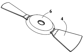
Figs. 1a and 1b show a target pigeon which comprises a
wing part 4 and a witness part 6. Also shown is the sec-
tion c-c which is depicted in fig. 6.
Fig. 2 shows a wing part 4 which comprises a substan-
tially ring-shaped body 8 and two wings 10. More than two
wings may be provided, e.g. three, four, etc. The ring-
shaped body 8 may be provided with a recess 14. The wings
10 are attached to the body 8 and are configured such
that they have a propeller effect when the target pigeon
rotates.
Fig. 3 shows a witness part 6 which comprises a disc-
shaped part 15 with a central hole 16. The central hole
16 may be provided with a toothing or other geometry
which is suitable for force-transferring engagement with
a launching machine. The toothing may be made as bendable
teeth so that they may be contacted with the launching
machine, without its driving means being in correct posi-
tion relative to the teeth, the engagement optionally
taking place, i.e. the teeth mesh, only when a force is
applied from the launching machine. In addition to the
disc-shaped part 15, the witness part 6, in the embodi-
ment shown, is provided with a skirt 18 which has re-
cesses 20. The recesses 20 are to make room for the wings
10 on the wing part 4, when the wing part 4 and the wit-
ness part 6 are interconnected.
The wing part 4 and the witness part 6 are preferably
made of plastics and preferably in colours which have a
CA 02423873 2003-03-27
WO 02/27261 PCT/DKO1/00617
9
considerable contrast between them. A filler may have
been added to the plastics . The witness part 6 is pref-
erably made of a relatively ductile material which is
easily penetrated by pellets. The wing part is preferably
made of a more fragile or brittle material which splin-
ters and/or comes to pieces when it is hit by pellets, so
that the witness part 6 is separated with certainty. The
material for the witness part 6 and.for the wing part 4
may e.g. be polystyrene, arid measures may have been taken
to ensure that the wing part 6 splinters more easily than
the wing part 4, e.g. by the addition of a filler.
Fig. 4 shows a witness part 6 which comprises a projec-
tion 22. This may engage the recess 14, so that relative
rotation between the witness part 6 and the wing part 4
may be prevented. Hereby, the force and the energy from
the launching machine may be applied to the witness part
6 and be transferred to the wing part 4. This may be done
in several ways which will be evident to a skilled per-
son, including also allowing the recesses 20 to extend
toward the wings 10. The recesses 20 may e.g. be provided
with a small projection which is suitable for gripping or
engaging a wing 10.
Fig. 5 shows a witness part 6 which comprises two holes
24 that are offset from the centre and arranged at a dis
tance of 180 degrees, making it possible to apply energy
for launching of the target pigeon. Hereby, the target
pigeon may also be launched on a launching machine of an
existing type.
Fig. 6 shows a witness part 6 and a wing part 4 which are
interconnected. In this embodiment, the interconnection
has taken place in that the witness part 6 has a protrud-
CA 02423873 2003-03-27
WO 02/27261 PCT/DKO1/00617
ing edge or edges 28 which have been pressed past an edge
26 on the wing part 4. This interconnection provides a
tight engagement between the wing part 4 and the witness
part 6, said two parts cooperating structurally and
5 achieving a good common strength and rigidity. This ef
fect may be achieved in several similar ways, which will
be evident to a skilled person. The figure moreover shows
that a skirt 18 is positioned close to a ring-shaped body
8, thereby minimizing the effective height of the target
10 pigeon.
When the target pigeon is launched, then it is inter alia
caused to rotate at a high speed. This results in consid-
erable stresses in the ring-shaped body 8 which approach
the ultimate stress. When the witness part 6 is made of a
material which is easily penetrated by pellets, then the
body 8 nevertheless splinters quite easily. That is that
even though the witness part 6 partly shades the body 8,
then the body will splinter nevertheless. Another possi-
bility is that the force from the pellet or pellets pene-
trate the interconnection, thereby separating the witness
part 6.
Fig. 7 shows a stack of target pigeons according to the
invention. As will appear from fig. 6, the witness part 6
and the wing part 4 may have predominantly parallel faces
so that the target pigeons are nested in each other in
such a manner that the height of the stack is not in-
creased by more than a few millimetres for each addi-
tional pigeon which is added to the stack. This configu-
ration of the target pigeon where the ring-shaped body 8,
the skirt 18 and the wings l.0 of the wing part 4 are made
with inclined faces, provides an optimum low effective
height of the stack, as the target pigeons fit in each
CA 02423873 2003-03-27
WO 02/27261 PCT/DKO1/00617
11
other. Because of the conicity of the body 8 and the
skirt 18, these have a stabilizing effect on the stack of
the target pigeons, which is instrumental in ensuring
that the target pigeons do not get displaced, thereby
minimizing the risk that a target pigeon is e.g. in an
oblique position and thereby causes malfunction of the
launching machine.
In the foreoing, the terms target pigeon and pigeon have
been used, but these terms are to be considered as having
the same meaning.