Note: Descriptions are shown in the official language in which they were submitted.
CA 02424097 2003-03-31
WO 02/30777 PCT/USO1/29518
-1-
POSITIVE-ORIENTATION SYSTEMS
FOR CLOSURES AND CONTAINERS
TECHNICAL FIELD
This invention relates to closure assemblies and to packages in the
form of a combination of a container and a closure assembly for the
container. More particularly, the invention relates to closure assemblies and
packages that provide positive-orientation of the closure assembly relative to
the container.
BACKGROUND OF THE INVENTION
AND
TECHNICAL PROBLEMS POSED BY THE PRIOR ART
Positive orientation systems for packages in the form of a container
and a closure assembly for the container are generally known in the prior art.
For example, U.S. Patent No. 5,145,00, the subject matter and entire writing
of which is incorporated herein by reference, discloses a closure assembly
that includes a closure body having a closure skirt with one or more recesses
on an interior surface of the closure skirt. The closure assembly is adapted
to engage a container neck finish that includes a threaded container neck
with protuberances formed on a base portion thereof. Each recess is adapted
to receive a protuberance. As the closure is rotated and threaded onto the
container neck, the closure skirt is initially engaged by and deformed
somewhat by the protuberances. Either the container neck or the closure
skirt, or both, must be sufficiently resilient to deform as the closure is
threaded onto the container neck so as to accommodate relative movement of
the protuberance and skirt until the protuberance is received in the recess.
When the recesses become aligned with the protuberances, the container skirt
or protuberance, or both, return to their undeformed shape, thereby retaining
the closure in a predetermined orientation on the container.
Positive-orientation systems of the prior art are characterized by a
number of disadvantages. For example, systems such as those described
CA 02424097 2003-03-31
WO 02/30777 PCT/USO1/29518
_2_
above require that the closure skirt have a wall thickness that is sufficient
to
accommodate the formation of recesses. On the other hand, such closures
require the closure body skirt wall or the protuberance, or both, to be of
such dimension to permit deformation without requiring undue rotational
force. Thus, the positive orientation features of prior art closure systems
impose limitations on the dimensional characteristics of the closure body
skirt wall and on the container neck finish protuberances and associated
limitations on the manufacturing techniques and aesthetic appearance of
closure assemblies.
It would therefore be desirable to provide a positive orientation
system in the form of a closure and container combination that avoid these
limitations. It would also be advantageous if such an improved closure
system could accommodate bottles, containers, or packages which have a
variety of shapes and that are constructed from a variety of materials.
Further, it would be desirable if such an improved system could
accommodate efficient, high-quality, large volume manufacturing techniques
with a reduced product reject rate to produce a system with consistent
operating characteristics.
BRIEF SITMMARY OF THE INVENTION
The benefits and advantages described above are realized by the
present invention which provides a package, including a closure and
container combination having positive-orientation features which do not
require deformation during installation and which therefore eliminate the
limitations imposed by prior art positive orientation systems.
In a broad sense, the invention comprises a positive orientation
container and closure combination comprising: (A) a container defining an.
interior and having a neck defining an opening to the interior, the neck
having at least one male neck thread with a predetermined root diameter; (B)
a closure cooperatively associated with the container neck for closing the
opening, the closure comprising a deck, a skirt extending from the deck and
CA 02424097 2003-03-31
WO 02/30777 PCT/USO1/29518
-3-
having at least one female skirt thread for threadingly engaging the neck
thread; and (C) an orientation structure on said closure and an orientation
structure on said container for engaging said orientation structure on said
closure to establish a positive orientation of the closure in an installed
position relative to the container, said orientation structure on said
container
being located within the container male neck thread root diameter and being
operable without deformation of the closure as the closure is screwed on to
the container neck.
In one preferred embodiment, the invention provides a closure having
a plug seal with at least one plug seal lug that cooperates with a container
neck lug formed on a shoulder on an interior surface of the container neck.
This aspect of the invention may be defined as a positive orientation
container and closure combination comprising: (A) a container body defining
an interior and having a neck including an interior neck surface and defining
an opening to the interior, the neck having at least one neck thread and at
least one container neck lug extending from the interior neck surface, the at
least one container neck lug having a container neck lug abutment surface;
and (B) a positive-orientation closure cooperatively associated with the
container neck for closing the opening; the closure including: (1) a closure
deck, (2) a skirt extending from the deck and having at least one skirt thread
formed thereon for threadingly engaging the at least one neck thread, (3) a
plug seal extending from the deck for sealingly engaging an interior surface
of the neck, and (4) at least one plug seal lug formed on the plug seal and
adapted to engage the at least one container neck lug abutment surface when
the closure is rotated to an installed position to thereby positively orient
the
closure with respect to the container. As the closure is screwed onto the
container neck, the at least one plug seal abutment surface eventually engages
the at least one neck lug abutment surface to prevent further rotation of the
closure relative to the container and thereby defines an installed position in
which the closure is positively oriented relative to the container.
CA 02424097 2003-03-31
WO 02/30777 PCT/USO1/29518
-4-
In another preferred embodiment, at least one neck lug is provided on
an end of the container neck and the closure body is provided with at least
one closure deck lug extending from the closure deck and adapted to engage
a corresponding one of the at least one neck lug. This feature of the
invention may be defined as a positive-orientation container and closure
combination comprising: (A) a container body defining an interior and
having a neck defining an opening to the interior, the neck having (1) at
least one neck thread formed thereon, (2) a neck end surface extending
around the opening, and (3) at least one neck lug extending from the end
IO surface; and (B) a positive-orientation closure rotatably cooperating with
the
container neck for closing the opening, the closure including: (1) a closure
deck; (2) a skirt extending from the closure deck and having at least one
skirt thread formed thereon for threadingly engaging the at least one neck
thread; and (3) at least one closure deck lug extending from the closure deck
and adapted to engage a corresponding one of the at least one neck lug when
the closure is rotated to an installed position to thereby positively orient
the
closure with respect to the container. As the closure is screwed onto the
container neck, the closure deck lug eventually engages the neck lug to
prevent further rotation of the closure relative to the container and thereby
def ne an installed position in which the closure is positively oriented
relative
to the container.
The novel positive orientation features provided by the invention can
easily be provided in closures and containers manufactured by injection
molding of thermoplastic materials. These features permit
positive-orientation without undue limitations on the dimensions of the
closure skirt and without requiring the relatively complicated manufacturing
steps associated with the formation of protuberances extending from the base
of the container neck.
CA 02424097 2003-03-31
WO 02/30777 PCT/USO1/29518
-5_
Numerous other advantages and features of the present invention will
become readily apparent from the following detailed description of the
invention, from the claims, and from the accompanying drawings.
~ItIEF DESCRIPTION OF 'THE DRAVfINGS
The accompanying drawings form part of the specification, and like
numerals are employed to designate like parts throughout the same.
In the accompanying drawings that form part of the specification, and
in which like numerals are employed to designate like parts throughout the
same,
Y 0 FIG. 1 is a fragmentary, exploded, perspective view of an exemplary
closure and container assembly according to a preferred embodiment of the
present invention;
FIG. 2 is a fragmentary, perspective view of the closure and container
of FIG. 1 with the closure mounted on the container and with the closure lid
in an opened position;
FIG. 3 is an enlarged, fragmentary, cross-sectional view taken
generally along the plane 3-3 in FIG. 2;
FIG. 4 is an enlarged, fragmentary, cross-sectional view taken
generally along the plane 4-4 in FIG. 3;
FIG. S is an enlarged, fragmentary, cross-sectional view taken
generally along the plane 5-5 in FIG. 3;
FIG. 6 is a fragmentary, exploded, perspective view of an exemplary
closure and container assembly according to another preferred embodiment of
the present invention;
FIG. 7 is a fragmentary, perspective view of the closure and container
of FIG. 6 with the closure mounted on the container and with the closure lid
in an opened position;
FIG. 8 is an enlarged, fragmentary, cross-sectional view taken
generally along the plane 8-8 in FIG. 7;
CA 02424097 2003-03-31
WO 02/30777 PCT/USO1/29518
-6-
FIG. 9 is an enlarged, fragmentary, cross-sectional view taken
generally along the plane 9-9 in FIG. 7;
FIG. 10 is an enlarged, fragmentary, side view of exemplary first and
second abutment surfaces of the embodiment shown in FIG. 7; and
FIG. 11 is a fragmentary, cross-sectional view taken generally along
the plane 11-11 in FIG. 10.
DETAILED DESCRIPTION OF
TAE PREFERRED ElVIBODIIVVIENTS
While this invention is susceptible of embodiment in many different
forms, this specification and the accompanying drawings disclose only some
specific forms as examples of the invention. The invention is not intended to
be limited to the embodiments so described, however. The scope of the
invention is pointed out in the appended claims.
For ease of description, most of the figures illustrating the invention
show a positive orientation system in the typical orientation that it would
have at the top of a container when the container is stored upright on its
base, and terms such as upper, lower, horizontal, etc., are used with
reference
to this position. It will be understood, however, that the positive
orientation
systems of this invention may be manufactured, stored, transported, used, and
sold in an orientation other than the position described.
Some of the positive-orientation systems provided by this invention
include closures which are intended for use with threaded containers having a
special finish configuration, while some other systems of the invention are
suitable for use with threaded containers having a conventional finish.
As used herein, the term "neck" is intended to mean any part of a
container in which threads or other fastening means for a closure are formed
or defined. The term "neck'° is not necessarily limited to a container
part
which is of a reduced diameter or reduced lateral dimension compared to the
container body. Thus, a container which has a threaded portion that is of an
CA 02424097 2003-03-31
WO 02/30777 PCT/USO1/29518
_7-
equal or similar width or diameter to the container body will also be
considered to have a "neck" in accord with the definition used herein.
a
Some of the figures illustrating the preferred embodiment of the
container and closure show conventional structural details and features that
will be recognized by one skilled in the art. Ilowever, a detailed description
of such details and features are not necessary for an understanding of the
invention, and accordingly, are not herein presented.
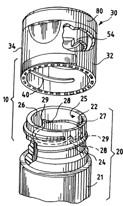
With reference to FIGS. 1-5, an exemplary positive-orientation system
is illustrated in a package, generally designated with the number 10 and
comprising a container 20 and a closure 30. Those of ordinary skill will
recognize that FIG. 1 illustrates only the neck portion of the container 20.
The container 20 typically includes a body portion or receptacle portion (not
visible in the figures) which may have any suitable special or conventional
configuration and from which neck 21 extends to receive the closure 30.
The container neck 21 includes a neck finish having at least one male thread
24 form on an outer surface thereof. The bottom or root of the thread form
(i.e., the innermost radial extent of the thread on the container neck)
defines
a predetermined minor diameter or root diameter.
According to the present invention, features of a novel positive
orientation system are provided on the container neck 21 and the closure 30
for establishing a predetermined orientation of the closure 30 relative to the
container 21 when they are assembled together. In particular, the container
neck 21 is provided with an orientation structure, such as at Least one
container neck lug 28, and preferably a pair of container neck lugs 28, which
extend from a container neck shoulder 27 (FIG. 1) formed on the interior of
the container neck 21 and which extend from an interior surface 25 of the
container neck wall 26. The shoulder 27 defines a smaller diameter portion
of the neck 21 and an enlarged diameter plug-receiving portion 22. The
container neck lugs 28 are preferably spaced about 180 degrees apart, and
each have a generally vertically extending container neck lug abutment
CA 02424097 2003-03-31
WO 02/30777 PCT/USO1/29518
_$_
surface 29 for engaging a respective plug seal lug 54 formed on the closure
30 as will be described below. The lugs 28 are preferably located within the
container neck within the container thread root diameter.
The closure 30 includes a closure body 32 which is of a generally
cylindrical shape and which includes a closure skirt 34 that extends
downward from substantially planar closure deck 35. A female thread 40
(FIGS. 1 and 3) is formed on an interior surface of the closure skirt 34. The
closure deck 35 includes a spout 38 which defines a dispensing orifice 44 for
permitting flow of contents from the container 20. The closure body 32 also
includes a plug seal 50 extending downward from the closure deck 35 and
having a rounded end surface 52 (FIGS. 3 and 5) to permit ease of insertion
of the plug seal into the enlarged diameter portion 22 of the container neck
21.
A lid 80 is pivotally attached to the closure body 32 by a hinge 82
and includes a lid sidewall or skirt 84 which extends to a lid seating surface
86 from a lid end wall 88. In the illustrated preferred embodiment, the lid
80 is connected to the closure body by a suitable means, such as a
snap-action hinge 82. Such a snap-action hinge 82 is formed integrally with
the closure body 32 and lid 80. The snap-action hinge 82 may be a
conventional or special type such as described in the IJ.S. Pat. No. 4,403,712
or LT.S. Patent No. 5,642,824. The Iid 80 includes an internal spud or ring
seal 90 for entering into and sealing the dispensing orifice 44. The lid 80 is
adapted to be moved between an open position (FIGS. 2 and 3) for
permitting the dispensing of the container contents and a closed position
(FIG. 1 ) in which the dispensing orifice 44 (FIG. 2) is occluded. In an
alternate embodiment (not illustrated), the hinge 82 could be omitted, and the
lid 80 may be completely removable from the closure body 32.
Preferably, the closure body 32, lid 80, and hinge 82 are molded as a
unitary structure from suitable thermoplastic materials compatible with the
container and its contents. The details of the particular hinge structure, lid
CA 02424097 2003-03-31
WO 02/30777 PCT/USO1/29518
-9-
structure, and closure body deck structure form no part of the present
invention. The closure 30 may include other dispensing features instead of
the spout 38 and dispensing orifice 44. For example, a special discharge
structure, such as a nozzle, spray device, or the like may be provided.
Alternatively, a plurality of dispensing orifices, or other structures for
discharging the container contents, may be provided in the closure body 32.
Depending upon the type of discharge structure incorporated, the full lid 80
may be entirely eliminated.
In accordance with the positive-orientation features of the invention,
the plug seal 50 is provided with an orientation structure, such as one, or
preferably two plug seal lugs 54 about 180 degrees apart (only one plug seal
lug 54 being visible in the figures), each having a plug seal lug abutment
surface 56 for engaging a respective container neck lug abutment surface 29.
As FIG. 3 illustrates, when the closure body 32 is screwed onto the container
neck 21 in a clockwise direction as viewed from above, the plug seal lug
abutment surfaces 56 of the plug seal lugs 54 will come into eventual
engagement with the container neck lug abutment surfaces 29, thereby
resulting in a positive orientation of the closure 30 relative to the
container
20. FIG. 4 illustrates a cross-sectional view taken along line 4-4 in FIG. 3
and shows one of the plug seal abutment surfaces 56 engaging one of the
neck lug abutment surfaces 29 and resisting further rotation of the closure 30
in the direction of arrow (A). FIG. 5 is a cross-sectional view taken along
line 5-5 in FIG. 3 and shows the rounded end surface 52 of the plug seal 50
and the axial extent (L) of one of the plug seal lugs 56. As will be
recognized, the axial extent (L) of the plug seal lugs 56 and their radial
position on the plug seal are selected, dependent upon the slope of the neck
thread 24 and, therefore, the slope of the closure skirt thread 40, to permit
maximal engagement of the plug seal lugs 54 with the container neck lugs
28.
CA 02424097 2003-03-31
WO 02/30777 PCT/USO1/29518
-10-
With reference to FIGS. 6-11, another exemplary positive-orientation
system is illustrated in a package, generally designated with the number I 10
and comprising a container 120 and the closure I30. In this embodiment, an
orientation structure is provided on the underside of the closure deck and
includes, in the illustrated preferred form, a pair of closure deck lugs 154
in
an annular space 152 (FIG. 3) between the plug seal 150 and closure body
skirt 134 of the closure body 132. In this embodiment, the container 120
includes a container neck I21 having a container neck end surface 123. An
orientation structure is provided in the container neck, and in the
illustrated
preferred ~orm, the orientation structure comprises a pair of neck lugs I28
which extend from the container neck end surface 123. Each lug 128
includes a generally vertical neck lug abutment surface 129. Each closure
deck lug 154 is adapted to engage a respective one of the two neck lugs 128
extending from the neck end' surface 123.
The container neck 121 includes a neck finish having at least one
male thread I24 or thread form on an outer surface thereof The bottom or
root of the thread form (i.e., the innermost radial extent of the thread 124
on
the container neck 121) defines a predetermined minor diameter or root
diameter.
The container neck lugs 128 are preferably located within the
predetermined root diameter of the container neck thread I24. That is, the
container neck lugs 128 do not extend radially outward on the wall of the
container neck 121 beyond the root of the neck thread 124.
The closure 130 includes a closure body 132 having a closure skirt
134 extending from a closure deck 135 which has a spout I38 defining a
dispensing orifice 144. A female thread I40 is formed on an interior surface
of the closure skirt 134 for engaging the container neck thread I24. As best
seen in the cutaway shown in FIG. 6 and the cross-section shown in FIG. 8,
the plug seal 150 extends from the closure deck 135, and the annular space
152 is defined between an exterior surface of the plug seal 150 and an
CA 02424097 2003-03-31
WO 02/30777 PCT/USO1/29518
-11-
interior surface of the closure skirt 134. In accordance with the invention,
the closure deck lugs 154 are located in the annular space 152, and each
includes a closure deck lug abutment surface 156. The closure body lugs
154 function to engage the neck lugs 128 when the closure body 132 is
rotated to an installed position shown in FIGS 7 and 8. The abutment
surfaces 129 formed on the neck lugs 128 are engaged by the abutment
surfaces 156 formed on the closure body plug lugs 154 to prevent further
rotation of the closure body 130 relative to the container 120.
The closure 130 also includes a lid 180 which is pivotally connected
to the closure body 132 by a snap action hinge 182. The lid 180 includes a
lid sidewall 184, a lid seating surface 186, and a lid end wall 188. An
orifice sealing member 190 is provided on the lid end wall 188.
FIG. 9 is a cross-sectional view taken along lines 9-9 in FIG. 7 and
shows the orientation of one of the closure deck lug abutment surfaces 156
relative to the container neck end surface 123. FIG. 10 is a fragmentary
view illustrating the abutment of one of the closure deck abutment surfaces
156 with one of the neck lug abutment surfaces 129, thereby preventing
further movement of the closure deck lug 154 in the direction of arrow (B).
FIG. 11 is a cross-sectional view taken along lines 11-11 in FIG. 10 and
shows the engagement of the closure deck lug abutment surface 156 with the
neck lug abutment surface 156 as viewed from above.
The present invention contemplates that the closure 30 or 130 includes
one or more features that are to be aligned in a particular orientation
relative
to the container 20 or 120, respectively. Such features may be include a
dispensing orifice. Alternatively, such a feature could also be a particular
thumb or finger grip area on the closure that is intended to be grasped in a
particular orientation relative to the container. If the closure includes a
lid, it
may be desired to orient the hinge part of the lid relative to one side of the
container--especially if the container has a non-cylindrical shape. With a
container of the type that has a non-cylindrical configuration, such as one
CA 02424097 2003-03-31
WO 02/30777 PCT/USO1/29518
- 12-
with flat sides and/or special gripping regions, it may be desirable to insure
that the lid, when opened, will have an orientation relative to the container
that will not inhibit the pouring or dispensing of the contents from the
container.
Finally, it may be desirable to orient the closure on the container for
reasons unrelated to the closure dispensing structure and/or lid. For example,
the closure may be molded with an unusual external configuration for
aesthetic or trade dress reasons, and it may be desired to ensure that such a
closure is mounted in a particular orientation relative to the container.
Alternatively, the closure may include preprinted text or graphic materials
for
which a particular orientation relative to the container is desired.
It will be readily apparent from the foregoing detailed description of
the invention and from the illustrations thereof that numerous variations and
modifications may be effected without departing from the true spirit and
scope of the novel concepts and principles of this invention.