Note: Descriptions are shown in the official language in which they were submitted.
CA 02424131 2003-04-O1
H101-3587 @@ O1
LIGHT PROJECTOR
BACKGROUND OF THE INVENTION
S This invention relates to a light projector such as a headlight for use with
a
vehicle.
The headlight for use with a vehicle is operated to light up under
circumstances
where a driver recognizes difficulty in seeing an area ahead of the vehicle
with the
unaided eye. The headlight is typically used in the nighttime, in a downpour
of rain,
t0 in fog, or in other similar conditions. Actually, in some instances where
the headlight
is lit in a downpour of rain or in fog, an irradiated light beam diffuses by
reflecting off
raindrops and fine particles of water vapor, and the driver's view is
obstructed by, .as it
were, a Light wall standing in front of the vehicle.
A technique utilizing polarization for a headlight of a vehicle is disclosed
in JP
t5 61-253236 A. The invention as disclosed in this publication is directed to
a technique
for preventing a headlight providing a high beam from dazzling a driver. To be
more
specific, two polarizing filters are provided: one is provided in an optical
path of the
headlight for irradiating a high beam, and the other is stuck on a windshield,
so that a
polarization axis of the latter is perpendicular to that of the former.
Accordingly, the
20 high beam is cut off using the two polarizing filters (one on the
windshield of the
driver's vehicle, and the other in the headlight of oncoming vehicles), and
the driver
can thereby be prevented from being dazzled.
However, in the invention disclosed in JP 61-253236 A, disadvantageously,
neither rain nor fog is envisaged as the problems to be addressed, and the use
of
25 polarizing filters would impair efficiency in utilization of light
irradiated by the
headlight. Moreover, the polarizing filter disadvantageously has low heat
resistance
CA 02424131 2003-04-O1
H101-3587 @@ 01
(only up to 50°C) in general, and thus attachment thereof to a
headlight or the use in
midsummer would significantly impair a polarizing capability thereof through
the
addition of heat derived from a lamp of the headlight or from sunbeams.
SUMMARY OF THE INVENTION
It is an exemplified general object of the present invention to provide a
light:
projector, in which the above disadvantages can be eliminated. Another
exemplified
and more specific object of the present invention is to provide a light
projector that: has
high efficiency in utilization of light irradiated from a headlight, and in
high heat
resistance, and that can ensure considerably increased forward visibility
under
conditions which would restrict the visibility.
A light projector according to the present invention includes a light source,
and
a polarized light sputter that splits a beam of unpolarized light irradiated
from the light
t5 source into p-polarized light and s-polarized light, and the p-polarized
light and/or the
s-polarized light are irradiated as vertical polarized light having electric
field plane of
vibration substantially vertical to level ground, and/or as horizontal
polarized light
having electric field plane of vibration substantially parallel to the level
ground.
With the light projector according to the present invention as above, a beam
of
light irradiated from the light source is split into p-polarized light and s-
polarized light,
and then the p-polarized light and/or the s-polarized light are utilized as
vertical
polarized light having electric field plane. of vibration substantially
vertical to level
ground and/or horizontal polarized light having electric field plane of
vibration
substantially parallel to the level ground; therefore, considerably increased
forward
visibility can be ensured under conditions which would restrict the visibility
while
keeping high efficiency in utilization of light and high heat resistance.
CA 02424131 2003-04-O1
H101-3587 @@. O1
Hereupon. the p-polarized light and the s-polarized light are defined in
relation
to the polarized light sputter; the p-polarized light has a direction of
vibration of the
electric field parallel to a plane of incidence of the polarized light
sputter, while the s-
polarized light has a direction of vibration of the electric field
perpendicular to the
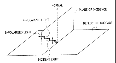
plane of incidence of the polarized light splitter. The plane of incidence is,
as shown
in FIG. l, a plane containing the normal at the point where incident light
strikes a
reflecting surface, and an optical axis of the incident light.
In contrast, the vertical polarized light and the horizontal polarized light
are
defined in relation to the direction of vibration of the electric field of the
polarized
light with respect to the ground to which light is irradiated. It is thus to
be understood
that the vertical polarized light and the horizontal polarized light are the
concepts
distinct from the p-polarized light and the s-polarized light as described
above. Light
having a direction of vibration of the electric field substantially vertical
to the level
ground (reflecting surface) is herein termed vertical polarized light, while
light having
a direction of vibration of the electric field substantially parallel to the
level ground
(reflecting surface) is herein termed horizontal polarized light. In other
words, the
vertical polarized light adequately refers to polarized light having a
direction of
vibration of the electric field substantially parallel to a plane of incidence
of light
which strikes the ground, and the horizontal polarized light adequately refers
to
polarized light having a direction of vibration of the electric field
substantially vertical
to the plane of incidence of light which strikes the ground.
Referring now to FIGS. 2A and 2B, a detailed description will be given of a
distinct difference in concept between the s- or p-polarized light and
vertical or
horizontal polarized light. FIG. 2A shows directions of vibration of p-
polarized light
and s-polarized light split by the polarized light sputter which is placed in
an
orientation as illustrated therein with respect to the ground. In FIG. 2A, the
p-
CA 02424131 2003-04-O1
H101-3587 @@ 01
polarized light that has been split off becomes vertical polarized light
having a
direction of vibration vertical (i.e.> perpendicular to the ground), and the s-
polarized
light that has been split off becomes horizontal polarized light having a
direction of
vibration horizontal (i.e., parallel to the ground).
FIG. 2B shows directions of vibration of p-polarized light and s-polarized
light
split by the polarized light splitter which is placed in an orientation tilted
with respect
to the ground. In this instance, as contrasted with the arrangement as shown
in FIG.
2A, the polarized light sputter tilts with respect to the ground; therefore,
the s-
polarized light is not identical with the horizontal polarized light, and the
p-polarized
1o light is not identical with the vertical polarized light.
In a light projector which embodies one exemplified aspect of the present
invention, one of the p-polarized light and the s-polarized light is
irradiated farther
from the light source as the vertical polarized light, and the other of the p-
polarized
light and the s-polarized light is irradiated to an area nearer to the light
source as the
horizontal polarized light.
It is generally known that the p-polarized light having a direction of
vibration
parallel to the plane of incidence exhibits lower reflectance than that of the
s-polarized
light having a direction of vibration vertical to the plane of incidence.
The vertical polarized light, if incident on top or under surfaces of
raindrops, or
2o the level ground, as reflecting surfaces, have a direction of vibration
parallel to the
plane of incidence; thus, the reflectance of the vertical polarized light
which strikes
the raindrops or a film of water on the surface of the road and reflects in a
vertical
direction is lower than that of the horizontal vertical polarized light, as is
the above-
described case with the p-polarized light.
4
CA 02424131 2003-04-O1
H101-3587 @@ O1
Reflection on the raindrops or the surface of the road which could impair
visibility is mainly derived from light reflected and diffused in a direction
vertical to
the ground.
Accordingly, irradiation of the vertical polarized light toward areas farther
from the light source makes it possible to restrict vertically diffusing
reflection, which
would be caused by raindrops, fine particles of water vapor, a film of water
on the
surface of the road generated in a downpour of rain or in heavy fog, and would
thus
impair visibility. Resultantly, the light projector according to this aspect
of the
present invention can maintain better forward visibility in comparison with
any
conventional light projectors that irradiate unpolarized light.
Moreover, irradiation of the horizontal polarized light toward areas nearer to
the light source makes it possible to ensure visibility of areas around the
light source,
and to enhance efficiency in utilization of light irradiated from the light
source.
In a light projector which embodies another exemplified aspect of the present
invention, one of the p-polarized light and the s-polarized light is
irradiated as first
vertical polarized light. and the other of the p-polarized light and the s-
polarized light
is changed into second vertical polarized light utilizing a phase changer and
irradiated
as the second vertical polarized light.
With the light projector according to this aspect of the present invention,
the p-
polarized light and s-polarized light that has been split by the polarized
light sputter
are both irradiated forward as the vertical polarized light, and such
arrangement makes
it possible to restrict vertically diffusing reflection, which would be caused
by
raindrops, fine particles of water vapor, a film of water on the surface of
the road
generated in a downpour of rain or in heavy fog, and would thus impair
visibility.
Consequently, the light projector according to this aspect of the present
invention can
CA 02424131 2003-04-O1
H101-3587 @@ O1
maintain better forward visibility under the bad conditions as above, in
comparison
with any conventional light projectors that irradiate unpolarized light.
In the light projector according to this aspect of the present invention, the
phase
changer may be a 112 wavelength retardation plate. The use of the 1/2
wavelength
retardation plate for the phase changer allows the light projector to change
the s-
polarized light or p-polarized light to vertical polarized light efficiently
with almost no
loss of the amount of light.
In the light projector according to every aspect of the present invention as
described above, the polarized light sputter may be made of material which is
to birefringent. The use of a birefringent material as the polarized light
sputter allows
the light projector to efficiently split unpolarized light into s-polarized
light and p-
polarized light.
The above-described light projector according to the present invention may be
used for a headlight for a vehicle. The vehicle that adopts the light
projector as
headlights thereof can reliably provide. the driver with better forward
visibility under
tough conditions (e.g., in heavy fog, or in a downpour of rain] in comparison
with any
conventional headlights.
Other objects and further features of the present invention will become
readily
apparent from the following description of preferred embodiments with
reference to
2o accompanying drawings.
BRIEF DESCRIPTION OF THE DRAWINGS
FIG. 1 shows a plane c>f incidence relative to a reflecting surface.
6
CA 02424131 2003-04-O1
H101-3587 @[a>, O1
FIG. 2A shows p-polarized light identical with vertical polarized light and s-
polarized light identical with horizontal polarized light, Generated by a
polarized light
sputter that is oriented vertically.
FLG. 2B shows p-polarized light and s-polarized light, generated by a
polarized
light sputter that is tilted with respect to the ground.
FIG. 3 shows a graph showing reflectance of p-polarized light and s-polarized
light each having a predetermined wavelength, incident on a surface of glass
material.
FIG. 4 shows shapes of water droplets flying from the air in heavy fog or in a
downpour of rain.
FIG. 5A is a schematic diagram showing distribution of light irradiated from a
headlight.
FIG. 5B is a schematic diagram showing diffusion of light which takes place as
a result of reflection of light beams irradiated from a headlight on the
surfaces of
raindrops.
FIG. 6 is a schematic dial=ram showing one exemplified embodiment of a light
projector according to the present invention.
FIG. 7A is a schematic diagram showing distribution of light irradiated from a
headlight resulting when a light projector according to the present invention
is lit in
heavy fog or in a downpour of rain.
2o FIG. 7B is a schematic diagram showing diffusion of light which takes place
as
a result of reflection of light beams irradiated from a light projector
according to the
present invention on the surfaces of raindrops.
FIG. 8 is a schematic diagram of a polarized light beam sputter.
FIG. 9 is a schematic diagram showing another exemplified embodiment of the
light projector according to the present invention.
7
CA 02424131 2003-04-O1
H101-3587 @~N, O1
DETAILED DESCRIPTION OF THE PREFERRED EMBODIMENTS
Exemplified embodiments of the present invention will be described with
reference made to the drawings as deemed appropriate.
The principle behind a light projector according to the present invention will
now be described to explain why improved forward visibility in comparison with
conventional light projectors can be provided.
FIG. 3 is a graph showing reflectance of p-polarized light and s-polarized
light
each having a predetermined wavelength, incident on a surface of a glass
material
to (refractive index = 1.51673). The ordinates represent reflectance, and the
abscissas
represent angles of incidence of a light beam where the angle formed with the
normal
of the surface (reflecting surface) of the glass material is zero degrees.
'the p-polarized light as herein referred to has a direction of vibration of
the
electric field parallel to the. plane of incidence, and corresponds to the
vertical
polarized light as defined in relation to the present invention which has a
direction of
vibration vertical with respect to the ground upon reflecting a surface
parallel to the
ground (.see FIG. 1 ). The s-polarized light, on the other hand, has a
direction of
vibration of the electric field vertical to the plane of incidence, and
corresponds to the
horizontal polarized light as defined in relation to the present invention
which ha.s a
2o direction of vibration horizontal with respect to the ground upon
reflecting a surface
parallel to the ground (see also FIG. I ).
Referring to the graph of FIG. 3, it is clearly shown that the reflectance of
the
s-polarized tight (horizontal polarized light) is greater than the reflectance
of the p-
polarized light (vertical polarized light), with the exception of cases where
the angle of
incidence is 0 degrees or 90 degrees. In particular, when the angle of
incidence ranges
between 20 degrees and 80 degrees, the reflectance of the s-polarized light
(horizontal
A
CA 02424131 2003-04-O1
H101-3587 @[a> 01
polarized light) is more than twice as great as the reflectance of the p-
polarized light
(vertical polarized light).
Although the above description relies upon FIG. 3 in which light strikes on a
surface of glass, the same is the case with water (a top or under surface
thereof) such
as a water droplet; namely, the reflectance of the p-polarized light (vertical
polarized
light) is greater than that of the s-polarized light (horizontal polarized
light).
Incidentally, when a headlight of a vehicle is lit up in heavy fog or in a
downpour of rain, irradiated light sometimes produces a phenomenon that seems
as if
a light wall emerges in front of the vehicle. so that the driver cannot
sufficiently be
to provided with good forward visibility in some instances. This is because
the light
irradiated from the headlight diffuses by reflecting off raindrops or fine
particles of
water vapor, and especially because the light diffusively reflects mainly in
directions
substantially vertical to the ground.
Shown in FIG. 4 are shapes of water droplets flying from the air in heavy tog
or in a downpour of rain. Each water droplet is substantially spherical in
shape, but
the larger a particle diameter thereof, the more oblate the water droplet is
made by air
resistance given during falling, and a superficies thereof increases
accordingly. The
water droplet, as thus shaped, makes the light irradiated from the headlight
and
incident thereon from a sideward direction diffuse in every direction,
particularly so as
2o to diffusively reflect in a direction substantially vertical to the ground.
Moreover,
since the number density or number of water droplets per unit volume is large
in heavy
fog or in a downpour of rain, the light once diffusively reflecting off the
water droplets
reflects off a great number of water droplets that exist in the neighborhood
again and
again, and an entire area irradiated by the light of the headlight
illuminates, and makes
the driver feel as if a light wall emerges near around the vehicle. In
particular, light
9
CA 02424131 2003-04-O1
H101-3587 @@ O1
reflecting in directions vertical to the ground obstructs the driver's view,
so that the
driver can hardly see a distant place.
Distribution of light irradiated from the headlight under the conditions as
described above is schematically shown in FIG. 5A. The light irradiated from
the
headlight randomly diffuses by reflecting off the surfaces of raindrops or
fine particles
of water vapor which exist on passages of the light, and forms a light wall
near around
the vehicle, making it difficult for the driver to get the visibility of areas
far from the
vehicle.
FIG. 5B is a schematic illustration of diffusion of light taking place by
reflecting off the surfaces of raindrops when the light is irradiated from a
headlight.
As shown in FIG. SB, the light repeatedly reflects on the surfaces of
raindrops in a
variety of directions, and gives an visual image as if a light wall emerges in
front of
the vehicle. Under the circumstances, the driver cannot see an object that
could be
seen under a normal condition.
Assuming that diffusion as a result of reflection of light irradiated from the
headlight on the surfaces of raindrops or fine particles of water vapor,
especially
vertically diffusive reflection which mainly impairs visibility, can be
restricted,
forward visibility can be ensured more reliably, and the vehicle can be
operated more
comfortably, than could be using a conventional headlight.
In order to actualize the above assumption, it is conceivable as one effective
means that the light irradiated from the headlight may be converted into
vertical
polarized light. This allows vertically diffusive reflection of light to be
considerably
reduced in comparison with the case in which unpolarized light is irradiated,
be<:ause
the reflectance of the vertical polarized light in a direction vertical to the
ground is
less than that of the horizontal polarized light. In other words, the above
means serves
to restrict the reflected light from diffusing in a vertical direction, and
thus serves to
l0
CA 02424131 2003-04-O1
H101-3587 @C~ of
prevent a light wall from being formed. Therefore, the driver's view is not
obstructed,
so that the driver can be reliably provided with good forward visibility.
FIG. 6 is a schematic diagram showing one exemplified embodiment of a light
projector according to the present invention. In the depicted embodiment,
light
irradiated from a light source is split into p-polarized light and s-polarized
light, so
that the p-polarized light is irradiated as first vertical polarized light,
and further the s-
polarized light formed by splitting the unpolarized light is changed into
second
vertical polarized light utilizing a phase changer and irradiated as the
second vertical
polarized light; consequently, the light projector irradiates the first and
second vertical
1o polarized light forward of a vehicle.
It is understood that a polarized light beam sputter 3 is provided as a
polarized
light splitting means in a manner as shown in FIG. 2A, and the following
equations are
thus satisfied: the p-polarized light = vertical polarized light; the s-
polarized light =
horizontal polarized light.
t5 The light projector according to the present embodiment includes a light
source
I, a collimating lens 2 for making light (unpolarized light) irradiated from
the light
source 1 into parallel beams of light by making angles of irradiation in
alignment with
one another, a polarized light beam sputter 3 for splitting the beams of light
from. the
collimating lens 2 into p-polarized light (first vertical polarized light) and
s-polarized
2o light (horizontal polarized light), a reflector ~ for reflecting the s-
polarized light
(horizontal polarized Light) generated by splitting the collimated beams of
light
utilizing the polarized light beam sputter 3, and a 112 wavelength retardation
plate (or
sheet) 6 for changing the s-polarized light (horizontal polarized light) into
second
vertical polarized light, with lenses Sa, Sb used for irradiating forward
light irradiated
25 from the light projector.
CA 02424131 2003-04-O1
H101-3587 @@ O1
Hereupon, the terms "polarized tight sputter" and "phase changer'' used for
describing the present invention correspond to the polarized light beam
sputter 3 and
the 112 wavelength retardation plate 6, respectively. In the present
embodiment, a
collimating lens is used to make light irradiated from the light source into
parallel
beams, but a concave mirror such as a parabolic ret~ector may be used instead.
Light (unpolarized light) irradiated from an HID (high intensity discharge)
Light
or other light source (light source l ) is converted into parallel beams using
the
collimating lens 2, and strikes on the polarized light beam sputter 3. P-
polarized light
formed herein does riot reflect in the polarized light beam splitter 3 but
passes through
the polarized light beam sputter 3, to reach the lens 5. and is irradiated
forward of the
vehicle as first vertical polarized light. On the other hand, s-polarized
light reflects
and changes a traveling direction thereof in the polarized light beam sputter
3, to reach
the reflector 4, in which an irradiating direction thereof is adjusted; the s-
polarized
light is then changed in direction of polarization upon passinc through the
1/2
wavelength retardation plate 6. and made into second vertical polarized light,
passing
through the lens 5b to be irradiated forward of the vehicle. The I!2
wavelength
retardation plate 6 is disposed in an orientation that tilts at 45 degrees
toward a
direction allowing the direction of polarization to change with respect to the
optical
axis so that the direction of polarization changes by an angle of 90 degrees.
As described above, in this embodiment of the light projector according to the
present invention, light irradiated from the light source 1 is split up into p-
polarized
light and s-polarized light; the p-polarized light is set to be first vertical
polarizE:d light,
and the s-polarized light is converted into second vertical polarized light,
so that only
the vertical polarized light having lower reflectance in a direction vertical
to the
ground is irradiated forward of the vehicle. Therefore, even in a downpour of
rain or
in heavy fog, diffusive reflection c:~f the light in the vertical direction,
which would be
12
CA 02424131 2003-04-O1
H101-3587 @@ O1
caused by raindrops or fine particles of water vapor, can be restricted,
whereby better
forward visibility as compared with conventional light projectors can be
ensured.
Advantageous effects of the light projector according to the present invention
are schematically illustrated in FIG. 7A. FIG. 7A is a schematic diagram
showing
distribution of light irradiated from a headlight as results when the light
projector
according to the present invention is lit up in heavy fog or in a downpour of
rain.
Vertical polarized light irradiated from the headlight of the present
invention is far less
likely to diffusively reflect in a vertical direction in comparison with
conventional
headlights that irradiate unpolarized light even if either light strikes on
raindrops or
to fine particles of water vapor alike. Accordingly, a light wall, so called,
does not
emerge in front of the vehicle, and thus the driver can be securely provided
with good
forward visibility. FIG. 7B is a schematic diagram showing diffusion of light
which
takes place on the surfaces of raindrops as a result of reflection of the
light beams
irradiated from the-light projector according to the present invention.
Irradiation of
vertical polarized light as in the present invention reduces the likelihood of
vertically
diffusing reflection that could take place on the surfaces of raindrops,
allowing the
driver to secure adequate forward visibility without obstruction of the light
wall.
Moreover, when the vehicle is operated at nighttime in a rainy day, light from
other vehicles reflecting off a water layer that exists on the road comes
within sii;ht of
the driver, and dazzlingly glares from the surface of the road, offering
extreme
difficulty to the driver who operates the vehicle. However, if the light
projector
according to the present invention comes into wide use among a great number of
vehicles. then the other vehicles also contribute restricted reflection of
irradiated light
on the surface of the road, so that the drivers can operate the vehicle more
comfortably.
Furthermore, the light projector- according to the present invention uses the
1/2
wavelength retardation plate 6 to change the s-polarized light, which has been
13
CA 02424131 2003-04-O1
H101-3587 @@ 01
produced by splitting up unpolarized light utilizing the polarized light beam
sputter 3,
into the second vertical polarized light. and thus light irradiated from the
light source I
can be utilized efficiently.
The polarized light beam sputter 3 as used herein may be implemented by
alternately laminating low-refractive-index films and high-refractive-index
films
between opposite surfaces of a pair of glass prisms, as shown in FIG. 8. The
polarized
light beam splitter 3 makes good use of a phenomenon in which incident light
striking
on a medium at a polarizing angle (Brewster's angle) makes the reflectance of
p-
polarized light zero and allows only s-polarized light to reflect. In the
polarized 1i ght
1o beam sputter 3, the reflectance and thickness of each film are
appropriately designed
so that the incident light strikes on the surface of the multilayered films at
the
polarizing angle. The use of the beam sputter 3 having the above structure
makes it
possible to split up the incident light to obtain p-polarized light and s-
polarized light
separately.
In order to split the light into s-polarized light and p-polarized light to be
irradiated at right angles with each other, the equation (I) is to be
satisfied:
n~ -2nN2nL2l(n~2 ~-nH2) (I )
2o where nN is the index of refraction of high-refractive-index films, nL is
the index of
refraction of low-refractive-index films, and n~ is the index of refraction of
glass.
For example, when ZrO~ (ntf=2.04) and MgF~ (nL=1.385) are used as the high-
refractive-index films and the low-refractive-index films, respectively, the
glass prism
made of glass having the index of refraction (jz~) of I .62 may be used.
t4
CA 02424131 2003-04-O1
H101-3587 @@ O1
Although the multilayered structure of high-refractive-index films and Iow-
refractive-index-films is emphasized and enlarged in FIG. 8, actual
thicknesses thereof
are much less than illustrated.
Alternatively, a device that utilizes a birefringent material to split a light
beam
into p-polarized light and s-polarized light may be adopted as the polarized
light beam
sputter 3. When an unpolarized light beam is let into a birefringent material,
the light
beam can be split into two components: i.e., a p-polarized light component and
an s-
polarized light component, different from each other in propagation velocity
at which
each component is transmitted through a crystal of the material, so that the p-
polarized
to light and the s-polarized light can be obtained separately. Among materials
usable~ as
the birefringent material are, for example, Calcite (CaCO~) and the like. That
is, the
polarized light beam sputter 3 made o.f calcite crystal can be used to obtain
p-polarized
light and s-polarized light separately.
The light projector according to the present invention splits light irradiated
t5 from a light source into p-polarized light and s-polarized light, changes
the s-polarized
light into vertical polarized light and irradiates the ve-rtical polarized
light forward of
the vehicle; thus, there should inevitably arise small losses of the amount of
light in
each of the steps (of splitting light into s-polarized light and p-polarized
light, and
changing the s-polarized light into vertical polarized light). However, the
light
2o projector according to the present invention holds promise of resulting
improvernent in
forward visibility under unfavorable conditions to such an extent as to more
than
offset the undesired losses. The light source 1 used herein is not limited to
an HID
lamp, but a lamp using a filament may be employed as usual.
Further, in the present embodiment, the s-polarized light obtained by
splitting
25 unpoIarized light using the polarized light beam sputter 3 is changed into
second
vertical polarized light using the I/2 wavelength retardation plate 6, and
irradiated
t5
CA 02424131 2003-04-O1
H101-3587 @@ O1
forward of the vehicle together with first vertical polarized light, but a
light projector
in which the 112 wavelength retardation plate 6 is not employed can also be
conceived.
To be more specific, another exemplified embodiment of the light projector
according to the present invention as shown in FIG. 9 has the same
construction as the
light projector as shown in FIG. 6, except that no 1/2 wavelength retardation
plate t~ is
provided. In this light projector, the s-polarized light obtained by splitting
unpolarized
light using the polarized light beam sputter 3 is not changed into vertical
polarized
light, but irradiated to an area near the vehicle as horizontal polarized
light. As
diffuse reflection of light irradiated to the area near the vehicle poses no
serious
to problem, such irradiation of horizontal polarized light to the area near
the vehicle
serves to have a sufficient amount of light secured in the area near the
vehicle. On the
other hand, the vertical horizontal light based upon the p-polarized light is
irradiated
to an area farther from the vehicle, and thus improved visibility in a far
area can be
ensured even under unfavorable conditions.
is Furthermore. although the light projector according to the present
invention is
exemplarily applied to a headlight such as a fog lamp in the above
embodiments, the
embodiments of the present invention are not limited thereto; i.e., any other
light
projectors such as a rear fog lamp, a tail lamp, a stop lamp, a back lamp,
etc. can be
implemented according to the present invention. The use of the light projector
20 according to the present invention for the lamps as recited above in a
vehicle enables a
driver of another vehicle that follows to easily recognize the presence of the
vehicle
ahead of his/her own vehicle, even under tough conditions that would restrict
forward
visibility to an inadequate level (e.g., in a downpour of rain, in heavy fog.
etc.),
because light irradiated from the lamps is restricted from reflecting off
raindrops or
25 fine particles of water vapor.
16
CA 02424131 2003-04-O1
H101-3587 @C,> O1
The light projector according to the present invention can be applied to a
searchlight, a flashlight, an illuminating device in a lighthouse, or the
like, as well.
The light projector according to the present invention applied to various
light
projectors for use in consumer goods, military installations, for recreational
use, for
security purposes, or the like can also provide improved forward visibility as
compared with conventional light projectors, in heavy fog, in rain, or in
adverse
conditions of various kinds, in a variety of situations.
Although the preferred embodiments of the present invention have been
described above, the present invention is not limited to the explicitly
described
to embodiments; namely, various modifications and changes may be made in the
present
invention without departing from the spirit and scope thereof.
The present invention constructed as described above produces distinctive
advantageous effects as follows.
The light projector as one aspect of the present invention is designed to
split
IS light irradiated from a light source into p-polarized light and s-polarized
light using a
polarized light sputter, and to irradiate the p-polarized light and the s-
polarized light
as vertical polarized light having electric field plane of vibration
substantially vf:rtical
to the ground, and/or as horizontal polarized light having electric field
plane of
vibration substantially parallel to the ground. This arrangement has high
efficiency in
20 utilization of light, and high heat resistance, and can provide
considerably increased
forward visibility under conditions which would restrict the visibility.
The light projector as another aspect of the present invention is designed to
irradiate vertical polarized light, which is low in reflectance of light in a
direction
vertical to the ground, to an area farther from the light source. This
arrangement can
25 contribute to reduced reflection of vertically diffusing light that would
take place on
surfaces of raindrops or fine particles of water vapor in a downpour of rain
or in heavy
i7
CA 02424131 2003-04-O1
H101-3587 @@. O1
fog. For example, a headlight for a vehicle to which the present invention is
applied
can provide a driver with sufficient forward visibility even under such
adverse
conditions. Moreover, the light projector is also designed to irradiate
horizontal
polarized light to an area nearer to the light source, and thus can utilize
light irradiated
from the light source efficiently, while ensuring the driver's view near the
vehicle.
The light projector as yet another aspect of the present invention is designed
to
split light irradiated from a light source into p-polarized light and s-
polarized light., to
irradiate one of the p-polarized light and the s-polarized tight as first
vertical polarized
light, and to change the other of the p-polarized light and the s-polarized
tight into
to second vertical polarized light utilizing a phase changer such as a 1/2
wavelength
retardation plate and irradiate the second vertical polarized light. This
arrangement
can increase the amount of light of the vertical polarized light, which is low
in
reflectance of light in a direction vertical to the ground, allowing a driver
to be more
reliably provided with forward visibility, in a case where this aspect of the
present
invention is applied to a headlight of a vehicle, for example.
A birefringent material may be used for the above polarized light sputter, and
if
so, unpolarized light generated from the light source can efficiently be split
up into s-
polarized light and p-polarized light.
The light projector according to the present invention may be used for a
2o headlight of a vehicle, which serves to achieve considerably increased
forward
visibility of a driver in heavy fog or in a downpour of rain in comparison
with a
conventional headlight.
18