Language selection

Search

Patent 2424194 Summary

Third-party information liability

Some of the information on this Web page has been provided by external sources. The Government of Canada is not responsible for the accuracy, reliability or currency of the information supplied by external sources. Users wishing to rely upon this information should consult directly with the source of the information. Content provided by external sources is not subject to official languages, privacy and accessibility requirements.

Claims and Abstract availability

Any discrepancies in the text and image of the Claims and Abstract are due to differing posting times. Text of the Claims and Abstract are posted:

  • At the time the application is open to public inspection;
  • At the time of issue of the patent (grant).
(12) Patent: (11) CA 2424194
(54) English Title: DRILL STRING SHOCK ABSORBER
(54) French Title: AMORTISSEUR DE TRAIN DE TIGES
Status: Expired and beyond the Period of Reversal
Bibliographic Data
(51) International Patent Classification (IPC):
  • E21B 17/07 (2006.01)
(72) Inventors :
  • GIEN, BERNARD LIONEL (South Africa)
(73) Owners :
  • BERNARD LIONEL GIEN
(71) Applicants :
  • BERNARD LIONEL GIEN (South Africa)
(74) Agent: MACRAE & CO.
(74) Associate agent:
(45) Issued: 2007-10-09
(22) Filed Date: 2003-03-31
(41) Open to Public Inspection: 2003-10-10
Examination requested: 2003-08-25
Availability of licence: N/A
Dedicated to the Public: N/A
(25) Language of filing: English

Patent Cooperation Treaty (PCT): No

(30) Application Priority Data:
Application No. Country/Territory Date
2002/2791 (South Africa) 2002-04-10

Abstracts

English Abstract


The invention concerns a shock absorber for a borehole drilling machine to
absorb axial and torsional loads having a pair of components for connection to
each other in a drill string, each component having a circumferentially
extending series of lobes and a plate with inwardly extending lobes between
the lobes of the components, a resilient member located between the
components and fastening means extending between the plates on one side
of the member and the lobes on the component on the other side.


Claims

Note: Claims are shown in the official language in which they were submitted.

6
CLAIMS
1. A borehole drilling machine shock absorber comprising a pair of oppositely
disposed circumferentially flanged components adapted for connection into a
drill string, each flange providing a series of outwardly projecting
perforated
lobes symmetrically positioned with a resilient member located between the
flanges, the flanged components being relatively offset circumferentially, a
pair
of annular plates providing inwardly extending perforated lobes located
between the lobes of the flanges and fastening means extending between the
lobes of the annular plates on one side of the resilient member and the lobes
on the flange of the flanged component on the opposite side of the resilient
member.
2. A borehole drilling machine shock absorber as claimed in claim 1 in which
the flanged components have oppositely disposed hollow central bosses which
overlap axially.
3. A borehole drilling machine shock absorber as claimed in claim 2 in which
the flanged components have oppositely disposed hollow central bosses which
overlap axially in sealing engagement with each other.
4. A borehole drilling machine shock absorber as claimed in claim 1 in which
the fastening means are nuts and bolts.

Description

Note: Descriptions are shown in the official language in which they were submitted.


CA 02424194 2003-03-31
2
DRILL STRING SHOCK ABSORBER
FIELD OF THE INVENTION
This invention relates to shock absorbers which are included in drill strings
used
with borehole drilling machines.
BACKGROUND TO THE INVENTION
Drilling machines utilize drill strings to transmit power down predrilled
holes to a
drill bit at the bottom of the hole. The drill bit may be operated by a down-
the-hole
hammer assembly or by a rotary action.
Whatever method is used it is highly desirable that a shock-absorber be
incorporated in the drill string between the bit and the driving head. This is
usually done by positioning the shock-absorber between the driving head and
the
first drill rod of the drill string.
Known types of shock absorbers, which must absorb axial shock loading and the
torque applied to the drill string, have either cumbersome casings with two
sets of
rubber elements or one element with straps holding the top and bottom halves
of
the shock absorbers together.
Applicant's earlier South African Patent No 94/2201 discloses a shock absorber
which to a large extent eliminated the problems above referred to resulted in
a
somewhat cumbersome construction which induced undesirable stresses in the
connecting bolts during operation of the drill.

CA 02424194 2003-03-31
OBJECT OF THE INVENTION
It is the object of the present invention to provide a shock absorber which is
more
cost effective and technically more advantageous than the applicant's earlier
construction.
SUMMARY OF THE INVENTION
In accordance with this invention there is provided a borehole drilling
machine
shock absorber comprising a pair of oppositely disposed circumferentially
flanged
components adapted for connection into a drill string, each flange providing a
series of outwardly projecting perforated lobes symmetrically positioned with
a
resilient member located between the flanges, the components being relatively
offset circumferentially, a pair of annular plates providing inwardly
extending
perforated lobes located between the lobes of the flanges and fastening means
extending between the lobes of the plates on one side of the resilient member
and the lobes on the flange of the component on the opposite side of the
member.
2~ The invention further provides for the fastening means to be bolts and nuts
and
for the resilient member and the plates to have a circular shape.
BRIEF DESCRIPTION OF THE DRAWINGS
These and other features of this invention will become apparent from the
following description of a preferred embodiment in which:
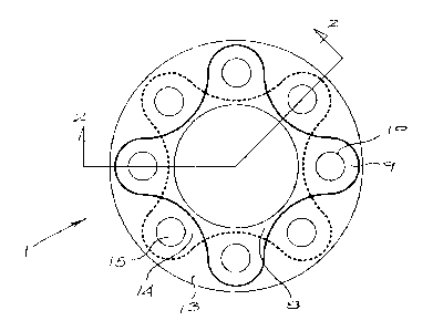
FIG.1 shows a plan view of a shock absorber; and
FIG .2 shows a longitudinal cross-section of Fig 1.

CA 02424194 2003-03-31
4
DETAILED DESCRIPTION OF THE INVENTION
As illustrated the shock absorber (1 ) for a drill string (not shown) consists
of two
components (2) and (3) for attachment in a drill string for a borehole drill.
The
component (2) is for attachment to the drill head (not shown) and component
(3)
will in use be secured to the first drill rod (not shown) of the drill string.
The usual
tapered threads will be used to join the components into the drill string.
The components (2) and (3) have oppositely disposed hollow central bosses
which overlap axially and are sealingly engaged with each other as indicated
at
(4).
Component (2) has an outwardly extending flange (5) which, as can be seen in
Figure 2, carries peripheral outwardly extending lobes (6) symmetrically
arranged
around the periphery of the flange (5). Each lobe (6) has an aperture (7)
therethrough.
Similarly component (3) has a flange (8) and lobes (9) with apertures (10)
therethrough.
A cylindrical resilient member (12) engages over the component (3) and is
located between the flanges (5) and (8) of components (2) and (3).
When the components (2) and (3) are assembled with the resilient member (12)
the lobes (5) and (8) are symmetrically circumferentially offset to extend
between
each other.
At each end of the resilient member (12) is an annular rigid plate (13). The
interior periphery of these plates (13) are also shaped to have inwardly
projecting
symmetrically located lobes (14). These lobes (14) locate between the lobes
(6)

CA 02424194 2003-03-31
and (9) as can be seen in Figure 1 and the lobes (14) are also perforated as
shown at (15)
The resilient member (12) has passages (16) therethrough arranged to be co-
axial with the apertures (7) and (10) and (15) through the lobes (6) and (9)
and
5 (14).
It will be appreciated that the components (2) and (3), resilient member (12)
and
annular plates (13) are, in use, arranged so that bolts (17) can be passed
through
flange (5), resilient member (12) and annular plate (13) adjacent flange (8).
Similarly, bolts can be passed through flange (8), the resilient member (12),
and
the plate (13) adjacent the flange (5).
With the bolts so secured the shock absorber (1 ) can cushion axial
intermittent
IS loads through the resilient member (12) being under compressive loads while
torsional loading is resiliently absorbed by the plates (13) and flanges (5)
and (8)
and the bolts.
It will be appreciated that both torsional and axial loads through the drill
string are
absorbed and the securing bolts are not subjected to bending loads such as, in
the past, have damaged the shock absorber (1 ).
Further the overall radial dimensions of the shock absorber can be kept
smaller
and the unit more compact than has been possible heretofore.
a0

Representative Drawing
A single figure which represents the drawing illustrating the invention.
Administrative Status

2024-08-01:As part of the Next Generation Patents (NGP) transition, the Canadian Patents Database (CPD) now contains a more detailed Event History, which replicates the Event Log of our new back-office solution.

Please note that "Inactive:" events refers to events no longer in use in our new back-office solution.

For a clearer understanding of the status of the application/patent presented on this page, the site Disclaimer , as well as the definitions for Patent , Event History , Maintenance Fee  and Payment History  should be consulted.

Event History

Description Date
Time Limit for Reversal Expired 2011-03-31
Letter Sent 2010-03-31
Grant by Issuance 2007-10-09
Inactive: Cover page published 2007-10-08
Pre-grant 2007-07-19
Inactive: Final fee received 2007-07-19
Letter Sent 2007-02-05
Notice of Allowance is Issued 2007-02-05
Inactive: Approved for allowance (AFA) 2006-12-29
Amendment Received - Voluntary Amendment 2006-06-02
Inactive: S.30(2) Rules - Examiner requisition 2006-03-22
Inactive: S.29 Rules - Examiner requisition 2006-03-22
Application Published (Open to Public Inspection) 2003-10-10
Inactive: Cover page published 2003-10-09
Letter Sent 2003-09-18
Request for Examination Requirements Determined Compliant 2003-08-25
All Requirements for Examination Determined Compliant 2003-08-25
Request for Examination Received 2003-08-25
Inactive: First IPC assigned 2003-06-27
Application Received - Regular National 2003-05-01
Filing Requirements Determined Compliant 2003-05-01
Inactive: Filing certificate - No RFE (English) 2003-05-01
Small Entity Declaration Determined Compliant 2003-03-31

Abandonment History

There is no abandonment history.

Maintenance Fee

The last payment was received on 2007-03-23

Note : If the full payment has not been received on or before the date indicated, a further fee may be required which may be one of the following

  • the reinstatement fee;
  • the late payment fee; or
  • additional fee to reverse deemed expiry.

Please refer to the CIPO Patent Fees web page to see all current fee amounts.

Fee History

Fee Type Anniversary Year Due Date Paid Date
Application fee - small 2003-03-31
Request for examination - small 2003-08-25
MF (application, 2nd anniv.) - small 02 2005-03-31 2005-01-20
MF (application, 3rd anniv.) - small 03 2006-03-31 2006-01-16
MF (application, 4th anniv.) - small 04 2007-04-02 2007-03-23
Final fee - small 2007-07-19
MF (patent, 5th anniv.) - small 2008-03-31 2008-01-31
MF (patent, 6th anniv.) - small 2009-03-31 2008-10-20
Owners on Record

Note: Records showing the ownership history in alphabetical order.

Current Owners on Record
BERNARD LIONEL GIEN
Past Owners on Record
None
Past Owners that do not appear in the "Owners on Record" listing will appear in other documentation within the application.
Documents

To view selected files, please enter reCAPTCHA code :


To view images, click a link in the Document Description column. To download the documents, select one or more checkboxes in the first column and then click the "Download Selected in PDF format (Zip Archive)" or the "Download Selected as Single PDF" button.

List of published and non-published patent-specific documents on the CPD .

If you have any difficulty accessing content, you can call the Client Service Centre at 1-866-997-1936 or send them an e-mail at CIPO Client Service Centre.


Document
Description 
Date
(yyyy-mm-dd) 
Number of pages   Size of Image (KB) 
Description 2003-03-31 4 135
Abstract 2003-03-31 1 14
Drawings 2003-03-31 1 22
Claims 2003-03-31 1 31
Representative drawing 2003-07-23 1 9
Cover Page 2003-09-12 1 34
Claims 2006-06-02 1 29
Abstract 2006-06-02 1 14
Cover Page 2007-09-17 1 34
Filing Certificate (English) 2003-05-01 1 159
Acknowledgement of Request for Examination 2003-09-18 1 173
Reminder of maintenance fee due 2004-12-01 1 110
Commissioner's Notice - Application Found Allowable 2007-02-05 1 161
Maintenance Fee Notice 2010-05-12 1 170
Correspondence 2007-07-19 1 32