Sélection de la langue

Search

Sommaire du brevet 2424194 

Énoncé de désistement de responsabilité concernant l'information provenant de tiers

Une partie des informations de ce site Web a été fournie par des sources externes. Le gouvernement du Canada n'assume aucune responsabilité concernant la précision, l'actualité ou la fiabilité des informations fournies par les sources externes. Les utilisateurs qui désirent employer cette information devraient consulter directement la source des informations. Le contenu fourni par les sources externes n'est pas assujetti aux exigences sur les langues officielles, la protection des renseignements personnels et l'accessibilité.

Disponibilité de l'Abrégé et des Revendications

L'apparition de différences dans le texte et l'image des Revendications et de l'Abrégé dépend du moment auquel le document est publié. Les textes des Revendications et de l'Abrégé sont affichés :

  • lorsque la demande peut être examinée par le public;
  • lorsque le brevet est émis (délivrance).
(12) Brevet: (11) CA 2424194
(54) Titre français: AMORTISSEUR DE TRAIN DE TIGES
(54) Titre anglais: DRILL STRING SHOCK ABSORBER
Statut: Périmé et au-delà du délai pour l’annulation
Données bibliographiques
(51) Classification internationale des brevets (CIB):
  • E21B 17/07 (2006.01)
(72) Inventeurs :
  • GIEN, BERNARD LIONEL (Afrique du Sud)
(73) Titulaires :
  • BERNARD LIONEL GIEN
(71) Demandeurs :
  • BERNARD LIONEL GIEN (Afrique du Sud)
(74) Agent: MACRAE & CO.
(74) Co-agent:
(45) Délivré: 2007-10-09
(22) Date de dépôt: 2003-03-31
(41) Mise à la disponibilité du public: 2003-10-10
Requête d'examen: 2003-08-25
Licence disponible: S.O.
Cédé au domaine public: S.O.
(25) Langue des documents déposés: Anglais

Traité de coopération en matière de brevets (PCT): Non

(30) Données de priorité de la demande:
Numéro de la demande Pays / territoire Date
2002/2791 (Afrique du Sud) 2002-04-10

Abrégés

Abrégé anglais


The invention concerns a shock absorber for a borehole drilling machine to
absorb axial and torsional loads having a pair of components for connection to
each other in a drill string, each component having a circumferentially
extending series of lobes and a plate with inwardly extending lobes between
the lobes of the components, a resilient member located between the
components and fastening means extending between the plates on one side
of the member and the lobes on the component on the other side.

Revendications

Note : Les revendications sont présentées dans la langue officielle dans laquelle elles ont été soumises.


6
CLAIMS
1. A borehole drilling machine shock absorber comprising a pair of oppositely
disposed circumferentially flanged components adapted for connection into a
drill string, each flange providing a series of outwardly projecting
perforated
lobes symmetrically positioned with a resilient member located between the
flanges, the flanged components being relatively offset circumferentially, a
pair
of annular plates providing inwardly extending perforated lobes located
between the lobes of the flanges and fastening means extending between the
lobes of the annular plates on one side of the resilient member and the lobes
on the flange of the flanged component on the opposite side of the resilient
member.
2. A borehole drilling machine shock absorber as claimed in claim 1 in which
the flanged components have oppositely disposed hollow central bosses which
overlap axially.
3. A borehole drilling machine shock absorber as claimed in claim 2 in which
the flanged components have oppositely disposed hollow central bosses which
overlap axially in sealing engagement with each other.
4. A borehole drilling machine shock absorber as claimed in claim 1 in which
the fastening means are nuts and bolts.

Description

Note : Les descriptions sont présentées dans la langue officielle dans laquelle elles ont été soumises.

CA 02424194 2003-03-31
2
DRILL STRING SHOCK ABSORBER
FIELD OF THE INVENTION
This invention relates to shock absorbers which are included in drill strings
used
with borehole drilling machines.
BACKGROUND TO THE INVENTION
Drilling machines utilize drill strings to transmit power down predrilled
holes to a
drill bit at the bottom of the hole. The drill bit may be operated by a down-
the-hole
hammer assembly or by a rotary action.
Whatever method is used it is highly desirable that a shock-absorber be
incorporated in the drill string between the bit and the driving head. This is
usually done by positioning the shock-absorber between the driving head and
the
first drill rod of the drill string.
Known types of shock absorbers, which must absorb axial shock loading and the
torque applied to the drill string, have either cumbersome casings with two
sets of
rubber elements or one element with straps holding the top and bottom halves
of
the shock absorbers together.
Applicant's earlier South African Patent No 94/2201 discloses a shock absorber
which to a large extent eliminated the problems above referred to resulted in
a
somewhat cumbersome construction which induced undesirable stresses in the
connecting bolts during operation of the drill.

CA 02424194 2003-03-31
OBJECT OF THE INVENTION
It is the object of the present invention to provide a shock absorber which is
more
cost effective and technically more advantageous than the applicant's earlier
construction.
SUMMARY OF THE INVENTION
In accordance with this invention there is provided a borehole drilling
machine
shock absorber comprising a pair of oppositely disposed circumferentially
flanged
components adapted for connection into a drill string, each flange providing a
series of outwardly projecting perforated lobes symmetrically positioned with
a
resilient member located between the flanges, the components being relatively
offset circumferentially, a pair of annular plates providing inwardly
extending
perforated lobes located between the lobes of the flanges and fastening means
extending between the lobes of the plates on one side of the resilient member
and the lobes on the flange of the component on the opposite side of the
member.
2~ The invention further provides for the fastening means to be bolts and nuts
and
for the resilient member and the plates to have a circular shape.
BRIEF DESCRIPTION OF THE DRAWINGS
These and other features of this invention will become apparent from the
following description of a preferred embodiment in which:
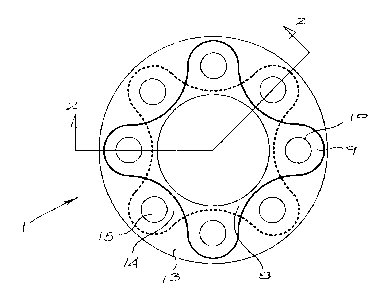
FIG.1 shows a plan view of a shock absorber; and
FIG .2 shows a longitudinal cross-section of Fig 1.

CA 02424194 2003-03-31
4
DETAILED DESCRIPTION OF THE INVENTION
As illustrated the shock absorber (1 ) for a drill string (not shown) consists
of two
components (2) and (3) for attachment in a drill string for a borehole drill.
The
component (2) is for attachment to the drill head (not shown) and component
(3)
will in use be secured to the first drill rod (not shown) of the drill string.
The usual
tapered threads will be used to join the components into the drill string.
The components (2) and (3) have oppositely disposed hollow central bosses
which overlap axially and are sealingly engaged with each other as indicated
at
(4).
Component (2) has an outwardly extending flange (5) which, as can be seen in
Figure 2, carries peripheral outwardly extending lobes (6) symmetrically
arranged
around the periphery of the flange (5). Each lobe (6) has an aperture (7)
therethrough.
Similarly component (3) has a flange (8) and lobes (9) with apertures (10)
therethrough.
A cylindrical resilient member (12) engages over the component (3) and is
located between the flanges (5) and (8) of components (2) and (3).
When the components (2) and (3) are assembled with the resilient member (12)
the lobes (5) and (8) are symmetrically circumferentially offset to extend
between
each other.
At each end of the resilient member (12) is an annular rigid plate (13). The
interior periphery of these plates (13) are also shaped to have inwardly
projecting
symmetrically located lobes (14). These lobes (14) locate between the lobes
(6)

CA 02424194 2003-03-31
and (9) as can be seen in Figure 1 and the lobes (14) are also perforated as
shown at (15)
The resilient member (12) has passages (16) therethrough arranged to be co-
axial with the apertures (7) and (10) and (15) through the lobes (6) and (9)
and
5 (14).
It will be appreciated that the components (2) and (3), resilient member (12)
and
annular plates (13) are, in use, arranged so that bolts (17) can be passed
through
flange (5), resilient member (12) and annular plate (13) adjacent flange (8).
Similarly, bolts can be passed through flange (8), the resilient member (12),
and
the plate (13) adjacent the flange (5).
With the bolts so secured the shock absorber (1 ) can cushion axial
intermittent
IS loads through the resilient member (12) being under compressive loads while
torsional loading is resiliently absorbed by the plates (13) and flanges (5)
and (8)
and the bolts.
It will be appreciated that both torsional and axial loads through the drill
string are
absorbed and the securing bolts are not subjected to bending loads such as, in
the past, have damaged the shock absorber (1 ).
Further the overall radial dimensions of the shock absorber can be kept
smaller
and the unit more compact than has been possible heretofore.
a0

Dessin représentatif
Une figure unique qui représente un dessin illustrant l'invention.
États administratifs

2024-08-01 : Dans le cadre de la transition vers les Brevets de nouvelle génération (BNG), la base de données sur les brevets canadiens (BDBC) contient désormais un Historique d'événement plus détaillé, qui reproduit le Journal des événements de notre nouvelle solution interne.

Veuillez noter que les événements débutant par « Inactive : » se réfèrent à des événements qui ne sont plus utilisés dans notre nouvelle solution interne.

Pour une meilleure compréhension de l'état de la demande ou brevet qui figure sur cette page, la rubrique Mise en garde , et les descriptions de Brevet , Historique d'événement , Taxes périodiques et Historique des paiements devraient être consultées.

Historique d'événement

Description Date
Le délai pour l'annulation est expiré 2011-03-31
Lettre envoyée 2010-03-31
Accordé par délivrance 2007-10-09
Inactive : Page couverture publiée 2007-10-08
Préoctroi 2007-07-19
Inactive : Taxe finale reçue 2007-07-19
Lettre envoyée 2007-02-05
Un avis d'acceptation est envoyé 2007-02-05
Inactive : Approuvée aux fins d'acceptation (AFA) 2006-12-29
Modification reçue - modification volontaire 2006-06-02
Inactive : Dem. de l'examinateur par.30(2) Règles 2006-03-22
Inactive : Dem. de l'examinateur art.29 Règles 2006-03-22
Demande publiée (accessible au public) 2003-10-10
Inactive : Page couverture publiée 2003-10-09
Lettre envoyée 2003-09-18
Exigences pour une requête d'examen - jugée conforme 2003-08-25
Toutes les exigences pour l'examen - jugée conforme 2003-08-25
Requête d'examen reçue 2003-08-25
Inactive : CIB en 1re position 2003-06-27
Demande reçue - nationale ordinaire 2003-05-01
Exigences de dépôt - jugé conforme 2003-05-01
Inactive : Certificat de dépôt - Sans RE (Anglais) 2003-05-01
Déclaration du statut de petite entité jugée conforme 2003-03-31

Historique d'abandonnement

Il n'y a pas d'historique d'abandonnement

Taxes périodiques

Le dernier paiement a été reçu le 2007-03-23

Avis : Si le paiement en totalité n'a pas été reçu au plus tard à la date indiquée, une taxe supplémentaire peut être imposée, soit une des taxes suivantes :

  • taxe de rétablissement ;
  • taxe pour paiement en souffrance ; ou
  • taxe additionnelle pour le renversement d'une péremption réputée.

Veuillez vous référer à la page web des taxes sur les brevets de l'OPIC pour voir tous les montants actuels des taxes.

Historique des taxes

Type de taxes Anniversaire Échéance Date payée
Taxe pour le dépôt - petite 2003-03-31
Requête d'examen - petite 2003-08-25
TM (demande, 2e anniv.) - petite 02 2005-03-31 2005-01-20
TM (demande, 3e anniv.) - petite 03 2006-03-31 2006-01-16
TM (demande, 4e anniv.) - petite 04 2007-04-02 2007-03-23
Taxe finale - petite 2007-07-19
TM (brevet, 5e anniv.) - petite 2008-03-31 2008-01-31
TM (brevet, 6e anniv.) - petite 2009-03-31 2008-10-20
Titulaires au dossier

Les titulaires actuels et antérieures au dossier sont affichés en ordre alphabétique.

Titulaires actuels au dossier
BERNARD LIONEL GIEN
Titulaires antérieures au dossier
S.O.
Les propriétaires antérieurs qui ne figurent pas dans la liste des « Propriétaires au dossier » apparaîtront dans d'autres documents au dossier.
Documents

Pour visionner les fichiers sélectionnés, entrer le code reCAPTCHA :


Pour visualiser une image, cliquer sur un lien dans la colonne description du document. Pour télécharger l'image (les images), cliquer l'une ou plusieurs cases à cocher dans la première colonne et ensuite cliquer sur le bouton "Télécharger sélection en format PDF (archive Zip)" ou le bouton "Télécharger sélection (en un fichier PDF fusionné)".

Liste des documents de brevet publiés et non publiés sur la BDBC .

Si vous avez des difficultés à accéder au contenu, veuillez communiquer avec le Centre de services à la clientèle au 1-866-997-1936, ou envoyer un courriel au Centre de service à la clientèle de l'OPIC.


Description du
Document 
Date
(aaaa-mm-jj) 
Nombre de pages   Taille de l'image (Ko) 
Description 2003-03-31 4 135
Abrégé 2003-03-31 1 14
Dessins 2003-03-31 1 22
Revendications 2003-03-31 1 31
Dessin représentatif 2003-07-23 1 9
Page couverture 2003-09-12 1 34
Revendications 2006-06-02 1 29
Abrégé 2006-06-02 1 14
Page couverture 2007-09-17 1 34
Certificat de dépôt (anglais) 2003-05-01 1 159
Accusé de réception de la requête d'examen 2003-09-18 1 173
Rappel de taxe de maintien due 2004-12-01 1 110
Avis du commissaire - Demande jugée acceptable 2007-02-05 1 161
Avis concernant la taxe de maintien 2010-05-12 1 170
Correspondance 2007-07-19 1 32