Note: Descriptions are shown in the official language in which they were submitted.
CA 02424507 2003-04-04
1
CERAMIC SUSCEPTOR
BACKGROUND OF THE INVENTION
Field of the Invention
The present invention relates to heaters in ceramics, and relates in
particular to heaters in ceramic susceptors employed in CVD devices, plasma
CVD devices, etching devices, and plasma etching devices for manufacturing
semiconductors, and in liquid-crystal manufacturing apparatuses.
Description of the Background Art
In ordex for the film-formation rates or etching rates in CVD (chemical
vapor deposition), plasma CVD, etching, or plasma etching on a semiconductor
wafer retained in a film-deposition chamber to take place uniformly, the wafer
surface temperature must be strictly controlled. For the purpose of such
temperature control, a heater is built into a wafer-retaining member, the
surface of the wafer-retaining member is heated, and a wafer of semiconductor
material is heated by thermal transfer. Ceramics endowed with heat-resistant,
corrosion resistant and insulative properties, such as aluminum nitride and
silicon nitride, have been employed to date as wafer retaining members of this
sort.
A wafer retaining member made of ceramic into which the foregoing
heater is built then has been manufactured according to a method that amounts
to sintering aluminum nitride and building-in a molybdenum coil, by training a
molybdenum coil into a groove formed in for example a disk-shaped aluminum
CA 02424507 2003-04-04
2
nitride plate, sandwiching it with another such aluminum nitride plate, and
hot-press sintering the sandwich.
In a wafer retaining member made of ceramic into which a heater is built,
i.e., a ceramic susceptor, the constituent components of the heater resistive
heating element are regarded as elemental impurities, even in trace amounts,
with respect to a semiconductor material for silicon wafers or the like, or a
liquid crystal material, and can become the source of malfunctioning in
semiconductor chips and liquid crystals.
Given the impurity threat, either a resistive heating element must be
completely embedded into a ceramic susceptor so as not to appear on the
surface,
or else a resistive heating element formed superficially on a ceramic must be
coated with a protective layer, within the chamber of semiconductor
manufacturing apparatuses. Consequently, an area in which the heating
element is not buried, i.e., a non-heating area, will necessarily be present
on the
outer peripheral portion of the ceramic susceptor. The heat generated by the
resistive heating element is transmitted through the ceramic, reaching the
surface, and from the surface then radiates or escapes via gases due to heat
transfer. This means that in disk-shaped or rectangular plate-shaped ceramic
susceptors the outer peripheral margin is therefore the place where heat is
most liable to escape.
Owing to the above-noted two causative factors taken together, the outer
periphery of a ceramic susceptor is the portion where temperature is most
prone
to drop. To address this issue, elimination of difference in temperature by
using
CA 02424507 2003-04-04
3
for the ceramic a material whose thermal conductivity is high, to swiftly
diffuse
toward the outer periphery the heat generated by the resistive heating
element,
has been practiced. Likewise another expedient has been to try to eliminate
the
temperature difference by increasing the winding density of the coil and the
pattern density of the resistive heating element the more toward the outer
periphery of the resistive heating element they are, to raise the heating
density
along, compensating with heat in, the outer periphery.
When a coil trained into a groove in a molded ceramic body is sandwiched
between molded ceramic bodies and worked in a hot press, however, it becomes
IO squashed into an indefinite shape and the outer peripheral edge of the
resistive
heating element in its substantive domain becomes disrupted. The
consequence of this has been that despite a resistive heating element being
isothermally designed by strictly reckoning how much heat it puts forth and
compensation for heat dispersion to its non-heated portions and for heat
escape
I5 from its edge portion, in practice, the substantive heat-issuing domain
becomes
disrupted in the edge portion, which has made it impossible to obtain desired
isothermal rating in the surface entirety of the ceramic susceptor.
Meanwhile, with the scaling-up of semiconductor wafer size in recent
years, isothermal demands on ceramic susceptors for heating the wafers have
20 become stricter, with an isothermal xating in the wafer-retaining face of
at
minimum within ~1.0%, preferably within ~0.5% being required.
CA 02424507 2003-04-04
4
SLJ1VIMARY OF THE INVENTION
An object of the present invention, in view of such circumstances to date,
is to realize a ceramic susceptor, being a plate-shaped sintered ceramic body
into which a coil-shaped resistive heating element is embedded, whose wafer-
retaining face excels in isothermal properties over its entire surface.
In order to achieve the foregoing objective, a ceramic susceptor that the
present invention realizes, being a resistive heating element formed in a
plate-
shaped sintered ceramic body, is characterized in that fluctuation in pullback
length between the outer peripheral edge of the sintered ceramic body and the
outer peripheral edge of the resistive heating element in its substantive
domain
is within ~0.8%. Furthermore, fluctuation in the pullback length is preferably
within ~0.5%.
A ceramic susceptor by the present invention as noted above may be
characterized in that the sintered ceramic body is made of at least one
substance type selected from aluminum nitride, silicon nitride, silicon
carbide,
and aluminum oxide. Furthermore, the resistive heating element may be
characterized in being made of at least one metal type selected from W, Mo,
Ag,
Pt, Pd, Ni and Cr.
As determined by the present invention, in terms of a ceramic susceptor
in which a coil-shaped resistive heating element is embedded into a plate-
shaped sintered ceramic body, by controlling fluctuation in the pullback
length
between the outer peripheral edge of the sintered ceramic body and the outer
peripheral edge of the resistive heating element in its substantive domain,
the
CA 02424507 2005-02-03
isothermal rating over the surface entirety of the wafer-retaining face can be
made the ~1.0% or less that has been demanded; more preferably, an isothermal
rating that is an outstanding f0.5% or less can, be achieved.
Broadly then, in one aspect, the invention provides a ceramic susceptor
comprising a plate-shaped sintered ceramic body being immutable to thermal
deformation at baking temperatures and having a surface processed to a
predetermined precision, a resistive heating element constituted from a paste
having a
predetermined composition, the paste being printed and baked under
predetermined
conditions onto the sintered ceramic body, the resistive heating element
defining a
substantive domain having an outer peripheral edge, wherein the precision in
the
surface of the ceramic body, the composition of the resistive-heating-element
paste,
and the baking conditions are each predetermined so as to control fluctuation
in
pullback length between the outer peripheral edge of the sintered ceramic body
and
the outer peripheral edge of the resistive heating element in its substantive
domain to
be within X0.8%.
from the following detailed description in conjwndion with the
accompanying drawings, the foregoing and other objects, featums, aspects and
advantages of the present invention will become readily apparent to those
skilled in the art.
CA 02424507 2005-02-03
Sa
BRIEF DESCRIPTION OF THE DRAWING
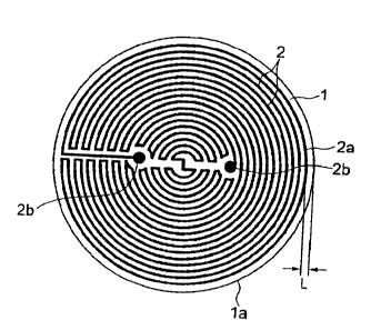
Fig. 1 is a plan viev~i illustrating an example of a rircoit pattern for a
resistive heating element.
DETAILED DESCRIPTION OF THE INVENTION
The present inventors discovered as a result of concerted investigations
that when forming a resistive heating element in a sintered ceramic body, by
getting the fluctuation in pullback length between the sintered member outer
peripheral edge and the resistive heating element substantive-domain outer
peripheral edge to be essentially within f0.8%, the isothermal rating of the
ceramic susceptor over its entire face satisfies the minimal requirement that
it
be within t1.0%.
They likewise discovered that by getting the fluctuation in pullback
length between the sintered ceramic body outer peripheral edge and the
resistive heating element substantive-domain outer peripheral edge to be
CA 02424507 2003-04-04
6
essentially within ~0.5%, the isothermal rating of the ceramic susceptor over
its
entire face will be the within -+-0.5% that has been most desirable.
An example of a resistive heating element embedded in a sintered
ceramic body is illustrated in Fig. 1. The resistive heating element 2 that is
embedded in the sintered ceramic body 1 is formed into a coil-shaped circuit
pattern, and length L between outer-peripheral edge la of the sintered ceramic
body 1 and resistive heating element substantive-domain outer-peripheral edge
2a of resistive heating element 2 is the pullback length. It will be
appreciated
that through lead lines from its two circuit ends 2b, 2b the resistive heating
element 2 forming the coil shape is rendered externally accessible, wherein
supplying electric power from a power source causes it to generate heat.
Likewise it should be understood that the circuit pattern shown in Fig. 1 for
the
resistive heating element 2 is a single example, and does not mean that the
present invention is thereby limited.
In a situation in which the circuit pattern for the resistive heating
element is formed onto a molded ceramic body or a green sheet, sintering the
substrate and the circuit pattern proceeds while it is shrunk and made
compact.
In such cases, shrinking uniformly is extremely di~cult owing to non-uniform
volatilization of oxides as the sintering promoter, which is due to non-
uniformity in the sintering promoter and non-uniform carbon residues after
degreasing, and to fluctuations in the furnace internal temperature and
atmosphere when sintering, and the conformation of the domain in which the
resistive heating element is substantially present is liable to warp. By the
same
CA 02424507 2003-04-04
7
token, hot press sintering a molybdenum coil shaped as a heater, and a
molybdenum sheet, placed on a molded ceramic body deforms the outer
peripheral edge of the resistive heating element substantive domain because in
the hot-press sintering process the coil and the sheet become smashed and
crushed or warped or displaced.
Although the outer peripheral edge of the sintered ceramic body can be
processed to lend it precision, if the resistive heating element substantive
domain deforms, fluctuations will end up occurring in the pullback length
between the sintered ceramic body outer peripheral edge and the resistive
heating element substantive-domain outer peripheral edge. Strictly controlling
these factors so as to achieve uniformity, and getting the fluctuation in
pullback
length between the ceramic sintered member outer peripheral edge and the
resistive heating element substantive-domain outer peripheral edge to be
essentially within ~0.8%, desirably within ~0.5%, yields the superior
isothermal
properties mentioned above. It should be understood that the pullback length
can be appropriately determined according to the wafer or similar target.
As a method for in this way controlling ffuctuativns in the pullback
length to be within a certain range, printing, with a paste in which resistive-
heating-element components and a sintering promoter have been mixed and
kneaded, a sintered ceramic body-which after having already been sintered
will not shrink/deform any further-with a circuit, and subsequently baking
the circuit, onto a surface that has been processed to satisfactory precision
enables the resistive heating element circuit to be baked without being
CA 02424507 2003-04-04
deformed. By thereafter joining the sintered ceramic body on which the
resistive heating element circuit is baked and a sintered ceramic body of
identical outside diameter, employing a bonding material, a ceramic susceptor
inside of which a resistive heating element is embedded can be readily
manufactured. Alternatively, by coating the resistive heating element
superficially with a protective layer a ceramic susceptor including a
resistive
heating element can be readily manufactured.
From the perspectives of corrosion resistance, thermal conductivity, and
the like, it is preferable that the ceramic forming the sintered ceramic body
be
made of one substance type selected from aluminum nitride, silicon nitride,
silicon carbide, and aluminum oxide.
Likewise, a metal having corrosion resistance and an inherent resistance
value suited to generating heat, preferably at least one metal type selected
from
W, Mo, Ag, Pt, Pd, Ni and Cr, can be used for the resistive heating element.
.L~'mbodiments
A granulated powder was prepared by adding 0.8 weight % yttrium oxide
(Y2O3) as a sintering pxomoter and polyvinyl alcohol as a binder to aluminum
nitride (A1N) powder, dispersing and mixing these ingredients using a ball
mill
with ethanol as a solvent, and then spray-drying the mixture to granulate it.
After being sintered the granulated powder obtained was molded with a
uniaxial press into 2 plates whose dimensions were 355 mm diameter x 5 mm
thickness. These were degreased within a nitrogen gas stream at a
CA 02424507 2003-04-04
9
temperature of 800°C and then sintered at 1850°C in a nitrogen
gas stream,
whereby sintered A1N plates were manufactured. The thermal conductivity of
the sintered A1N plates was 180 W/mK. Both the top and bottom surfaces of the
obtained sintered AlN plates were polished using diamond grit.
Next, a coil-shaped pattern was printed onto one of the sintered A1N
plates using a tungsten slurry that was obtained by kneading and mi~~ing
tungsten powder to which 1 weight % yttrium and, as a binder, ethyl-cellulose
were added. The final pullback length of the outer peripheral edge of the
tungsten-pattern and the outer peripheral edge of the sintered A1N plate was
set herein to be 1.0 mm. The sintered A1N plate was degreased :in a
90°C
nitrogen gas stream, and then baked 2 hours as 1800°C.
Further, ethyl-cellulose was added to, mixed with, and kneaded into a
yzOs ~2~3 bonding material, which mixture was printed as pattern on the one
further sintered AlN plate. This was degreased within a 900°C nitrogen
gas
stream, and then the tungsten-pattern face and bonding-material face of the
two sintered AlN plates were matched and hot-press bonded under 50 g/cmz at
1750°C. The outer periphery of the joined body was thereafter processed
to
finish it into a round contour 350 mm in diameter.
Power was supplied through externally accessible lead lines from the
circuit ends to the obtained ceramic susceptor, heating the tungsten resistive
heating element, and results of measuring the isothermal rating in the wafer-
retaining face indicated a satisfactory isothermal rating of 500°C
~0.40%. In
this case, the ceramic susceptor was breached along the radial direction and
the
CA 02424507 2003-04-04
pullback length between the outer-peripheral edge of the tungsten resistive
heating element domain, and the outer peripheral edge of the sintered A1N
body,
(set value: 1.0 mm) was measured, wherein the fluctuation was ~0.2%.
Embodiment 2
5 A ceramic susceptor that, apart from being printed with a pattern in
which the outer peripheral edge of the resistive heating element domain was
distorted by changing only the pattern of the tungsten resistive heating
element,
was the same as that of Embodiment 1 was manufactured. Fluctuation in the
pullback length between the resistive heating element domain outer-peripheral
10 edge, and the sintered A1N body outer peripheral edge was measured in the
same manner as with Embodiment 1, with regard to obtained ceramic
susceptors of three kinds; and the isothermal rating of the wafer-retaining
face
was also measured.
Results were that when the fluctuation in pullback length was ~0.5%, the
isothermal rating of the wafer-retaining face was 500°C ~0.50%.
Likewise,
when the fluctuation in pullback length was ~0.75%, the isothermal rating was
500°C ~0.70%. And further, when the fluctuation in pullback length was
~0.8%,
the isothermal rating was 500°C ~0.95%.
Embodiment 3
A granulated powder was prepared by adding 0.8 weight % boron carbide
(B4C) as a sintering promoter and polyvinyl alcohol as a binder to silicon
carbide
(SiC) powder, dispersing and mi~dng these ingredients using a ball mill with
ethanol as a solvent, and then spray-drying the mixture to granulate it.
CA 02424507 2003-04-04
11
After being sintered the granulated powder obtained was molded with a
uniaxial press into 2 plates whose dimensions were 355 mm diameter x 5 mm
thickness. These were degreased within a nitrogen gas stream at a
temperature of 900°C and then sintered 5 hours at 1950°C,
whereby sintered
SiC plates were manufactured. The thermal conductivity of the sintered SiC
plates was 180 W/mK. Both the top and bottom surfaces of the obtained
sintered SiC plates were polished using diamond grit.
Formation of a tungsten resistive-heating-element circuit and bonding of
the two sintered plates was carried out by the same techniques as with
Embodiment 1; and the same evaluation as with Embodiment 1 was conducted
on the ceramic susceptor obtained, wherein the fluctuation in the pullback
length was ~0.3%, while the isothermal rating of the wafer-retaining face was
500°C ~0.46%.
Embodiment 4
A granulated powder was prepared by adding 2 weight % yttria and 1
weight % alumina as sintering promoters and polyvinyl alcohol as a binder to
silicon nitride (Si3N4) powder, dispersing and mixing these ingredients using
a
ball mill with ethanol as a solvent, and then spray-drying the mixture to
granulate it.
After being sintered the granulated powder obtained was molded with a
uniaxial press into 2 plates whose dimensions were 355 mm diameter x 5 mm
thickness. These were degreased within a nitrogen gas stream at a
temperature of 900°C and then sintered 4 hours at 1600°C,
whereby sintered
CA 02424507 2003-04-04
12
Si~N4 plates were manufactured. The thermal conductivity of the sintered Si3N4
plates was 22 W/mK. Both the top and bottom surfaces of the obtained sintered
Si;~N4 plates were polished using diamond grit.
Further, ethyl-cellulose was added to, mixed with, and kneaded into a
low-melting-point glass bonding material, which mixture was printed as
pattern on the one further sintered Si3N4 plate. This was degreased within a
700°C atmospheric air stream, and then the tungsten-pattern face and
bonding-material face of the two sintered Si3N4 plates were matched and hot-
press bonded under 10 g/cm2 at 800°C. The outer periphery of the joined
body
was thereafter processed to finish it into a round contour 350 mm in diameter.
The same evaluation as with Embodiment 1 was conducted on the
ceramic susceptor obtained, wherein the fluctuation in the pullback length was
~0.3%, while the isothermal rating of the wafer-retaining face was
500°C
~0.45%.
E~bo-~Qnt 5
Apowder prepared by adding to, and dispersing into and mi~dng together
with, aluminum oxide (A120~ powder 1 weight % magnesia (Mg0) as a sintering
promoter and polyvinyl alcohol as a binder, and drying the mixture, was molded
with a uniaxial press into 2 plates whose post-sintering dimensions were 355
mm diameter x 5 mm thickness.
These were degreased within an atmospheric air stream at a
temperature of 700°C and then sintered 3 hours at 1600°C,
whereby sintered
plates were produced. The thermal conductivity of the A12O3 plates was 20
CA 02424507 2003-04-04
13
W/mK. Both the top and bottom surfaces of the obtained sintered A1203 plates
were polished using diamond grit.
Formation of a tungsten resistive-heating-element circuit and bonding of
the two sintered plates was carried out by the same techniques as with
Embodiment 4; and the same evaluation as with Embodiment 1 was conducted
on the ceramic susceptor obtained, wherein the fluctuation in the pullback
length was ~0.3%, while the isothermal rating of the wafer-retaining face was
500°C ~0.46%.
Embodiment 6
By a technique that, apart from a paste for forming the resistive-
heating-element circuit being rendered by adding 1 weight % yttria to
molybdenum powder and to this mi~ng in by kneading ethyl-cellulose as a
binder, was the same as that of Embodiment 1, a joined body from sintered A1N
plates was fabricated, and in the same manner thereafter a ceramic susceptor
was manufactured.
The same evaluation as with Embodiment 1 was conducted on the
ceramic susceptor obtained, wherein the fluctuation in the pullback length
between the outer-peripheral edge of the molybdenum resistive heating
element domain, and the outer peripheral edge of the sintered A1N body was
~0.3%, while the isothermal rating of the wafer-retaining face was
500°C
~0.46%.
Two sintered aluminum nitride plates were produced by the same
CA 02424507 2003-04-04
14
method as with Embodiment 1. Utilizing a paste in which a sintering promoter
and as a binder ethyl-cellulose were added and knead-mixed into Ag-Pd powder,
a circuit was formed on one of the plates, which was baked in air at
900°C. The
same method as with Embodiment 4 was utilized for a way of joining these with
one further sintered-aluminum-nitride plate.
The same evaluation as with Embodiment 1 was conducted on the
ceramic susceptor obtained, wherein the fluctuation in the pullback length
between the outer-peripheral edge of the Ag-Pd resistive heating element
domain, and the outer peripheral edge of the sintered A1N body was ~0.3%,
while the isothermal rating of the wafer-retaining face was 500°C
~0.45.
Embodiment.$
Two sintered aluminum nitride plates were produced by the same
method as with Embodiment 1. Utilizing a paste in which a sintering promoter
and as a binder ethyl-cellulose were added and knead-mixed into Ni-Cr powder,
a circuit was formed on one of the plates, which was baked in air at
700°C. The
same method as with Embodiment 4 was utilized for a way of joining these with
one further sintered-aluminum-nitride plate.
The same evaluation as with Embodiment 1 was conducted on the
cexamic susceptor obtained, wherein the fluctuation in the pullback length
between the outer-peripheral edge of the Ni-Cr resistive heating element
domain, and the outer peripheral edge of the sintered A1N body was ~0.3%,
while the isothermal rating of the wafer-retaining face was 500°C
~0.46.
CA 02424507 2003-04-04
Embodiment 9
A substrate onto which was baked a tungsten resistive heating element
was produced by the same method as with Embodiment 1. Onto this resistive
heating element was spread 100 ,can of a paste in which Y203 and ethyl-
cellulose
5 binder were knead-mixed into aluminum nitride powder. This was degreased
within nitrogen at 900°C baked 2 hours at 1800°C.
The same evaluation as with Embodiment 1 was conducted on the
ceramic susceptor obtained, wherein the fluctuation in the pullback length
between the outer-peripheral edge of the tungsten resistive heating element
10 domain, and the outer peripheral edge of the sintered A1N body was ~0.2%,
while the isothermal rating of the wafer-retaining face was 500°C
~0.40.
Comparative Example 1
Two molded aluminum nitride plates were fabricated by the same
method as with Embodiment 1. One plate was spread with the same tungsten
15 paste as in Embodiment 1, while the one other plate was spread with the
same
bonding-material paste3 as in Embodiment 1. The two plates were stacked
matching the tungsten-paste face with the bonding-material-paste face, and
while 50 kfg/cm2 pressure was applied were simultaneously baked at
1850°C.
The same evaluation as with Embodiment 1 was conducted on the
ceramic susceptor obtained, wherein isothermal rating in the wafer-retaining
face was 500°C ~1.30%. Further, the ceramic susceptor was breached
along the
radial directson and fluctuation in the pullback length between the outer-
peripheral edge of the tungsten resistive heating element domain, and the
outer
CA 02424507 2003-04-04
16
peripheral edge of the sintered A1N body was measured, wherein it was ~1.2%.
Two molded aluminum nitride plates were fabricated by the same
method as with Embodiment 1. A groove 4.5 mm in width, 2.~ mm in depth was
formed in each. A molybdenum coil was trained into the groove, and the 2
molded plates were stacked together so as to build-in the molybdenum coil and
were hot-press sintered in nitrogen for 2 hours under 100 kfg/cm2,
1850°C.
The same evaluation as with Embodiment 1 was conducted on the
ceramic susceptor obtained, wherein isothermal rating in the wafer-retaining
face was 500°C ~1_70%. Further, the ceramic susceptor was breached
along the
radial direction and fluctuation in the pullback length between the outer-
peripheral edge of the tungsten resistive heating element domain, and the
outer
peripheral edge of the sintered A1N body was measured, wherein it was ~1.5.
Only selected embodiments have been chosen to illustrate the present
invention. Zb those skilled in the art, however, it will be apparent from the
foregoing disclosure that various changes and modifications can be made herein
without departing from the scope of the invention as defined in the appended
claims. Furthermore, the foregoing description of the embodiments according
to the present invention is provided for illustration only, and not for
limiting the
invention as defined by the appended claims and their equivalents.