Note: Descriptions are shown in the official language in which they were submitted.
CA 02424659 2008-12-04
TUBULAR CONDUIT OR CONTAINER FOR TRANSPORTING OR STORING
CRYOGENIC MEDIA AND METHOD FOR PRODUCING THE SAME
The invention relates to a pipe-like line or
container for transporting or keeping cryogenic media,
in particular liquefied gases, for example liquid
hydrogen, with a multi-layered construction, the line or
the container having at least one layer of fiber
filaments embedded in thermally cured resin and provided
with at least one flange or connecting piece, which is a
separate part and is sheathed on the outside by at least
one layer of fiber filaments embedded in thermally cured
resin. The invention also relates to a process for
producing a pipe-like line or a container for
transporting or keeping cryogenic media, in particular
liquefied gases, for example liquid hydrogen, the line
or the container being provided and using a mandrel with
at least one layer of fiber filaments impregnated with
thermally curable resin and being provided with at least
one flange or connecting piece, which is a separate part
and is sheathed on the outside by at least one layer of
fiber filaments impregnated with thermally cured resin.
Hydrogen, which on account of its low molecular
weight and its high gross calorific value is considered
to be a fuel of the future, requires for its use in
cryogenic form
AMENDED SHEET
CA 02424659 2003-04-03
12-13-2002 AT0100318
- 2 -
correspondingly heat-insulated tanks and also correspondingly
heat-insulated fuel lines which can withstand the loads
occurring. Tanks and fuel lines must have not only good
insulating properties but also a construction that is as
lightweight and compact as possible.
Various structural designs have already been
proposed for storage containers or pipelines for cryogenic
media. EP-A-0 465 252 discloses a container of the type
stated at the beginning. This container is provided on the
outside with a layer of a composite material, which is
produced in such a way that a fiber filament is continuously
wound and subsequently embedded in a matrix of plastic. FR-A
2 753 257 discloses a pipeline for cryogenic liquid which,
considered from the inside outward, is made up of an inner
pipe made of iron-nickel alloy, a thin layer of aluminum,
adjoining that a layer of carbon fibers, a heat insulation of
superinsulating material and an outer sheathing. GB-A 3 897
490 is likewise concerned with a system of lines for very
low-temperature media, for example helium, in which an inner
pipe and an outer pipe are provided, with a wire mesh in
which a heat insulation comprising coated metal foils has
been applied to the outer side of the inner pipe. The space
between the inner pipe and outer pipe is additionally vacuum-
insulated.
AMENDED SHEET
CA 02424659 2003-04-03
12-13-2002 AT0100318
- 2a -
In the case of the known structural designs, the
required connecting pieces or flanges are separately joined
together with the pipelines. For this purpose, adhesive
bonding or welding is used for example. The connecting
points of the flanges specifically are often weak points,
since, for design reasons, on the one hand the insulation is
deficient here and on the other hand the forces occurring
during operation, in particular torsional forces, often
cannot be adequately absorbed here.
This is where the invention comes in, the object of
which is to design pipelines or containers for cryogenic
media and produce them by a technical process in such a way
that the problems mentioned in the transitional region or
connecting region with respect to flanges and the like no
longer occur, at least broadly.
As far as the structural design of the pipeline or
the container is concerned, the set object is achieved
according to the invention by the flange or the connecting
piece sitting on at least one layer of fiber filaments
embedded in thermally cured resin and having been integrated
in such a way into the construction of the line or the
container.
AMENDED SHEET
CA 02424659 2003-04-03
12-13-2002 AT0100318
- 3 -
As far as the process is concerned, the set object
is achieved according to the invention by at least one layer
of fiber filaments impregnated in thermally curable resin, on
which the flange or the connecting piece is positioned, being
applied to the mandrel, the flange or the connecting piece
being sheathed on the outside with at least one further layer
of fiber filaments impregnated in thermally curable resin,
the resin being thermally cured and the mandrel being
removed.
The separate subsequent connection of the flanges
or the connecting pieces to the finished pipeline or the
container is therefore no longer necessary, since these
connecting pieces are or have been integrated into the
pipeline or the container. The incorporation of the
connecting pieces takes place with fiber-reinforced plastic,
which is prepared from resin-impregnated fiber filaments.
This allows not only an absolutely sealed connection of these
parts to one another but also the required capacity for
absorbing forces to be ensured.
The torsional and shearing forces occurring during
operation can be absorbed particularly well if as many of the
component parts or layers as possible, but at least the
innermost and/or outermost layer, of the pipe-like line or
the container consist of fiber-reinforced plastic (claim 2).
AMENDED SHEET
CA 02424659 2003-04-03
- 4 -
Lines or containers designed according to the
invention are particularly stable and nevertheless also
adequately flexible if the layers of fiber-reinforced plastic
comprise at least one spirally wound fiber filament which is
embedded in the plastic and is wound at least substantially
transversely in relation to the longitudinal extent of the
line or the container (claims 3 and 4).
The layer incorporating the connecting pieces has
in particular a woven fabric embedded in plastic, the
filaments of which are oriented at an angle of the order of
45 in relation to the longitudinal extent of the line or the
container (claims 5 and 6). This ensures very good capacity
for absorbing torsional forces in the otherwise very
problematical transitional regions to the connecting pieces.
In the case of a preferred embodiment of the line
or the container, a supporting tube or a supporting casing
which is sheathed together with the connecting piece or
pieces by a layer of fiber-reinforced plastic is arranged
around the inner layer, at a distance from it (claim 7).
This creates a structural design in which the intermediate
space between the layer concerned and the supporting tube or
supporting casing can be evacuated as an additional
insulating measure.
In addition, annular transitional pieces, by which
the distance between the supporting tube or supporting casing
CA 02424659 2003-04-03
- 5 -
and the adjacent inner layer is set or maintained, may be
contained between the supporting tube or the supporting
casing and the connecting piece or pieces (claim 8).
For the intended uses of transporting or keeping
cryogenic media, carbon or glass fibers are suitable in
particular as the fibers and a resin is suitable in
particular as the plastic (claims 9 and 10).
The line or the container can be produced in a
simple, efficient and consequently also very cost-effective
way.
In this connection, it is provided for example that
the individual component parts or layers are applied step-by-
step to a mandrel, which is removed after completion of the
line or the container (claim 12).
In this case, a layer of a resin-impregnated fiber
filament is applied directly to the mandrel as the innermost
layer (claim 13). At least one further layer of resin-
impregnated fiber filaments is also applied to the fiber
filaments incorporating the connecting pieces (claim 14).
This allows a certain flexibility to be achieved along with
great strength and very good capacity for absorbing forces.
Production of the individual layers is made
particularly simple if they are created by spirally winding a
fiber filament which has been drawn through a resin bath, the
fiber filament being wound at least substantially
CA 02424659 2003-04-03
- 6 -
transversely in relation to the longitudinal extent of the
line or the container (claims 15 and 16).
According to a preferred embodiment of the
invention, the fiber filaments incorporating the connecting
pieces are in this case a component part of a fiber fabric
which is wound with a fiber filament impregnated in resin
(claim 17). The fiber fabric therefore need not be
separately impregnated with resin, which likewise simplifies
production.
If the fiber fabric is applied in the form of a
hose or flexible tube, this also makes the production process
more efficient (claim 18).
For the capacity to absorb torsional forces in the
region of the connecting pieces, it is of advantage in
particular if the fiber fabric is applied in such a way that
the filaments are oriented at an angle of the order of 45 in
relation to the longitudinal extent of the line or the
container (claim 19).
A separate supporting tube or a supporting casing
can be positioned and incorporated in a simple way using
transitional pieces during the production of the line or the
container (claim 20).
In this case, to ensure a solid bond between the
individual component parts, the connecting piece or pieces,
the transitional piece or pieces and the supporting tube or
CA 02424659 2003-04-03
- 7 -
the supporting casing are together sheathed with resin-
impregnated fiber filaments (claim 21).
For the intended uses, fiber filaments of carbon
fiber or glass fiber are particularly suitable (claim 22).
To ensure at least largely matching extensibility
of main component parts of the line or the container, it is
of advantage if the supporting tube or the supporting casing,
the connecting pieces and the transitional pieces consist of
the same type of fiber, in particular of carbon fiber (claim
23).
Further features, advantages and details of the
invention are now described in more detail on the basis of
the drawing, which contains schematic representations of
exemplary embodiments of the invention and in which:
figure 1 shows an exemplary embodiment of a
pipeline produced according to the invention and configured
according to the invention with an integrated connecting
piece, the left-hand half representing a longitudinal section
and the right-hand half representing the view from outside,
and
figure 2 shows a second exemplary embodiment of a
pipeline in a representation analogous to figure 1.
Both the structural design and the production of
pipelines configured according to the invention are explained
CA 02424659 2003-04-03
- 8 -
below on the basis of the two exemplary embodiments
represented in the figures of the drawing.
The embodiments represented concern, by way of
example, pipelines of circular cross section, as can be used
for instance as fuel lines for cryogenic fuel, for example
liquid hydrogen, in space shuttles.
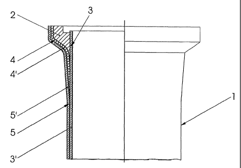
Figure 1 shows a piece of a pipe 1 with a flange or
connecting piece 2 integrated into the end region of the
pipe. A further connecting piece, configured in an identical
or different way, may also be provided at the second end of
the pipe (not represented). The structural design of the
pipe 1 and the integration of the connecting piece 2 are
evident from the type of production, which is described in
more detail below.
A mandrel (not shown in figure 1), which may for
example consist of metal, is used for producing the pipe.
The mandrel has an outer contour which corresponds to the
inner side of the pipe 1 to be formed. The pipe 1 is built
up on the mandrel from at least two layers. The innermost
layer 3 is created by winding around the mandrel a carbon
fiber filament 3, which during the winding operation is drawn
through a resin bath in a known way. The winding operation
is performed in such a way that the carbon fiber filament is
wound spirally in at least one layer, so that the layer 3'
produced is closed and consequently sealed. The intended or
CA 02424659 2003-04-03
- 9 -
required connecting pieces 2 are subsequently fitted onto the
two end regions of the tubular layer 3'. Figure 1 shows one
of the connecting pieces 2, which is a prefabricated
component, which in particular likewise consists of carbon
fiber and can be produced by turning a thicker-walled carbon
fiber pipe. Matching of the material - here carbon fiber -
for the individual pipe layers and the connecting pieces 2 is
of advantage on account of the same extensibility. The
connecting pieces 2 may, however, also consist of a different
material, but with a similar extensibility to that of carbon
fiber.
As figure 1 shows, the connecting piece 2 is
configured in particular in such a way that its region fitted
on the end region of the pipe is provided with a tapering
cross section, in order to create a largely stepless
transitional region in relation to the layer 3 on the
outside. A hose or a flexible tube 4 of carbon fiber fabric
is pulled over the connecting piece 2 and at least also part
of the layer 3'. The hose or flexible tube 4 of carbon fiber
fabric is preferably pulled over the entire length of the
layer 3' and both connecting pieces 2 and is extensible at
least to the extent that it can be pulled over the outer side
of the connecting piece 2 and the region of the layer 3
adjacent to the latter and also makes good contact there.
The individual filaments, the warp and weft threads, of which
CA 02424659 2003-04-03
- 10 -
the fabric consists are oriented in the hose or flexible tube
4 in particular in such a way that they can absorb forces,
torsional forces and flexural stresses particularly well in
the finished pipeline. This is the case in particular with
an orientation of the filaments at an angle of 45 or around
45 with respect to the longitudinal extent of the pipe 1.
A carbon fiber filament 5 which has previously been
drawn through a resin bath is again wound spirally over the
pulled-on or positioned hose or flexible tube 4. During the
winding of the resin-impregnated carbon fiber filament 5, the
hose or flexible tube 4, consisting of carbon fiber fabric,
is also impregnated with resin. After completion of the
outer layer 5' by winding the carbon fiber filament 5 one or
more times, the pipe 1, now finished in terms of
construction, is exposed to heat in an autoclave, in order
thermally to cure the resin constituents. The completed pipe
1 is finally pulled off the mandrel.
The winding of the carbon fiber filament to produce
the layers 3' and 5' is preferably performed at a small angle
of, in particular, 1 to 5 in relation to the transverse
direction of the pipe 1, the individual windings being wound
close together, as already mentioned.
The pipe 1 produced in this way consequently
comprises two plastic layers 3', 5', reinforced with carbon
CA 02424659 2003-04-03
- 11 -
fiber, integrated connecting pieces 2 and a further plastic
layer 4', which is reinforced with carbon fiber and
incorporates the connecting pieces 2.
The second embodiment of a pipeline, represented in
figure 2, additionally provides a double-walled construction
of the pipe 11 with vacuum insulation and, if appropriate,
with separate radiation protection. The production of this
configurational variant is performed in a way similar to that
according to figure 1.
As in the case of the embodiment according to
figure 1, firstly a resin-impregnated carbon fiber filament
13 is wound onto a mandrel (not represented in figure 2). A
prefabricated supporting tube 6 or a supporting casing, which
in particular consists likewise of carbon fiber and the
inside diameter of which is greater than the outside diameter
of the inner layer 13', is positioned onto the inner layer
13' created in this way, with the aid of transitional pieces
7 at both its end regions. Each transitional piece 7 is
configured as a ring which is divided into two at the center.
The ring or each ring half has a base part 7a, which runs
around in the form of a circular ring, and a casing 7b, which
is set at an acute angle from said base part on the outer
edge. The base part 7a and the casing 7b end on the inside
at matching diameters, which correspond to the outside
diameter of the inner layer 13'.
CA 02424659 2003-04-03
- 12 -
Formed on the outside of the base part 7a is a
peripheral supporting shoulder 7d, where the end of the
supporting tube 6 is supported or positioned. The base part
7a is provided with a number of holes 7c, the function of
which is discussed further below. With the supporting tube 6
positioned and held by means of the transitional piece 7,
sufficient space remains with respect to the free end of the
inner layer 13' for the fitting on and positioning of a
connecting piece 12. A hose or flexible tube 14 of carbon
fiber fabric, the configuration of which may correspond to
that according to the first exemplary embodiment, is pulled
over the connecting piece 12, the second connecting piece
(not represented), the transitional pieces 7 and the
supporting tube 6. Subsequently, an outer layer 15' is
formed by winding a resin-impregnated carbon fiber filament
15 around the hose or flexible tube 14. The resin-
impregnated carbon fiber filament also soaks the pulled-on
hose or flexible tube 14. After ending the winding
operation, the tube 11 is finished by thermal curing of the
resin and the mandrel is removed.
The completed pipe 11 therefore has, viewed from
the inside outward, a construction with a carbon fiber
reinforced inner plastic layer 13' and a supporting tube 6
which is at a distance from the latter and is sheathed on the
outside by two further carbon fiber reinforced layers 14' and
CA 02424659 2003-04-03
- 13 -
15'. The connecting piece 12 is integrated into this
construction by the sheathing with the layers 14' and 15'.
As figure 2 shows, an insulating vacuum can be
generated in the space between the supporting tube 6 and the
inner layer 13' by means of a nipple 9 subsequently
introduced from outside through the casing 7b of the
transitional piece 7. The holes 7c in this case establish
the required connection from the interior of the transitional
piece 7 to the intermediate space mentioned.
In addition, a multi-layer insulation, which in a
known way comprises a number of layers, for example ten to
twenty layers, of film coated with aluminum, which are
insulated or separated from one another by a construction of
paper or plastic, may be introduced into the intermediate
space created by the supporting tube 6.
In the case of the embodiment represented and
described, carbon fiber is assumed as the material for the
filament to be wound and the woven fabric. Carbon fiber
filaments are the preferred material on account of their
physical properties. However, glass fibers or other fibers
also come into consideration.
As a departure from the embodiments represented and
described, it may also be provided, depending on the intended
use, to dispense with the fitting-on of a hose- or flexible
tube-like fabric. As an alternative to the form of a hose or
CA 02424659 2003-04-03
- 14 -
flexible tube, the fabric may also be fabricated in the form
of a strip and applied by winding it around. The number of
layers to be wound of the impregnated fiber filament for
producing the inner and outer layers depends on the internal
pressure occurring during operation, so that a higher
internal pressure can be absorbed by additional wound layers.
Furthermore, to improve the insulating effect or to ensure
the vacuum tightness, further layers, for example of metal
foil, may be introduced or provided in the pipe construction.
It is also possible for more than two layers of resin-
impregnated and wound filament to be provided. The
construction according to the invention and the process
according to the invention are not restricted to the
production of pipelines. In particular, cylindrically shaped
containers for keeping cryogenic media may also have a
construction according to the invention and be produced
according to the invention.