Note: Descriptions are shown in the official language in which they were submitted.
CA 02424804 2006-09-21
26158-190
- 1 -
A Method of and Apparatus for Assembling an Aircraft Wheel
or Brake Component on an Axle of an Undercarriage
The invention relates to a method of and apparatus
for assembling a wheel or brake component of an aircraft on
an axle of an undercarriage.
On large aircraft, the undercarriage includes
wheels of a substantial size and weight. For example, the
weight of a wheel may be 225 kg and around 1.5 metres in
diameter and, hitherto, assembling the wheels tends to be a
difficult exercise due to the following:
On the final assembly line, it is common practice
to roll the wheels up to the lowered undercarriage leg. In
certain instances, it is necessary for final assembly
personnel to roll the wheel as far as 200 metres across the
final assembly line. As will be appreciated, wheels of the
kind referred to above are heavy and difficult to handle.
Moreover, the tyres on the wheels are generally contoured
making it difficult to keep the rolling wheel upright. It
has been known for wheels to be dropped while they are being
rolled and it is also easy to bump into other equipment
causing damage leading to increased costs and wasted time.
Normally, the wheels have to be rolled and bumped over
hoses, etc. on the floor making it difficult to control the
wheel and involving two operatives.
As well as having to assemble wheels on to an
undercarriage leg, brake assemblies also need to be
assembled and, like the wheels, are heavy and difficult to
handle. Hitherto, such brake assemblies are manually lifted
and assembled on to an undercarriage axle which again can be
difficult to do and somewhat hazardous. Typically, brake
CA 02424804 2006-09-21
26158-190
- 2 -
assemblies have been transported to the final assembly line
by means of a trailer with several brakes on board.
Occasionally, due to the distance and road conditions in and
around the final assembly line, it has been known for brakes
to slip from the trailer on to the ground. Where that
happens, the brakes have to be returned to the manufacturer
for repair or even scrap. Depending upon the availability
of additional brake assemblies, delays can occur as well as
costs in repairing or replacing the damaged brake.
Normally, the brakes are lifted from the ground by
means of a hand pump tool but they still have to be lifted
the last 30 cm or so by assembly operatives and offered up
to the axle on the undercarriage. Again, the manual
manoeuvring involved can be a hazardous exercise bearing in
mind that, typically, brakes can weigh approximately 135 kg,
can be 0.5 m in diameter and 0.6 m in width. Occasionally,
it is necessary for the brakes to be lifted on to the axles
totally manually by two operatives with the only protection
for the brake being a foam block which is placed in position
under the brake to prevent damage to the brake if it slips
from the hands of the operators.
What is required is an improved and more efficient
way of assembling wheels and brakes on to the axles of an
aircraft undercarriage which will minimise the risk to
operatives, minimise the risk of damage and which will
generally lead to time and cost savings when compared to the
existing methods.
According to one aspect of the present invention,
there is provided a method of assembling an aircraft wheel
component or brake component on an axle of an undercarriage,
CA 02424804 2006-09-21
26158-190
- 3 -
the method comprising providing a holder for the component,
providing a mobile lifting device including a guiding
mechanism, using the lifting device to lift the holder with
the component therein to a position where the component is
substantially in axial alignment with the axle, assembling
the component on to the axle by moving the holder under
control of the guiding mechanism in an axial direction of
the axle thereby to guide the component axially into
position on the axle, and lowering the holder from the
assembled component.
According to a second aspect of the invention,
there is provided apparatus for assembling an aircraft wheel
component or brake component on an axle of an undercarriage,
the apparatus comprising a holder for the component and a
lifting device including a guiding mechanism, the lifting
device operable to lift the holder with the component
therein to a position substantially in axial alignment with
the axle and the guiding mechanism comprising rollers
mounted to enable the holder, with the component therein, to
be moved in an axial direction of the axle thereby allowing
the component to be guided on to the axle, the lifting
device subsequently being operable to lower the holder from
the assembled component.
By having the components such as a wheel already
mounted in a holder, the holder can be conveniently
deposited on the mobile lifting device without having to
roll the wheel along the ground and the lifting device can
then be moved to a position adjacent the undercarriage leg.
Once in that position, the lifting device can lift the
holder with the wheel therein until the wheel is in axial
alignment with the axle of the undercarriage.
CA 02424804 2006-09-21
26158-190
- 4 -
Similarly, where the component is in the form of a
brake, it is unnecessary to lift the brake manually to a
position where it can be assembled onto the axle and,
therefore, the method is less hazardous than the one used
hitherto. The invention is, therefore, a significant
improvement over the current manner of assembly.
As the method comprises the step of moving the
holder in the axial direction of the axle to assemble the
component on the axle, the component remains in the holder
during assembly of the component onto the axle. In that
way, the component can remain safely in the holder up until
the point that it is safely in position on the axle. The
holder can then be removed and assembly personnel have the
knowledge that the wheel is securely assembled on the axle.
The method can comprise transporting the component
from a store to a location where the component may be
positioned on the lifting device. Preferably, the method
involves transporting the component from the store with the
component already positioned in its holder. Once a suitable
transporter has carried the holder and the component therein
to a position adjacent the lifting device, means such as a
fork lift truck can be used to transfer the holder from the
transporter to the lifting device. Preferably the
transporter transports a plurality of said components
simultaneously which, again, saves time in the assembly
process.
The holder may be in the form of a cradle in which
the component sits and the cradle may be formed by a
substantially cylindrical wall of the holder which supports
the component. Retainer means may be provided to prevent
the component slipping out of the cradle.
CA 02424804 2006-09-21
26158-190
- 4a -
The lifting device may be mobile and may have
ground wheels. The lifting device is preferably in the form
of a wheeled trolley to enable the component carried thereby
to be moved into an appropriate position relative to the
undercarriage.
Therefore, the lifting device can be moved to a
location convenient for the transfer of the holders from the
transporter to the lifting device. The lifting device can
then be pulled manually or driven to a position adjacent the
undercarriage leg where upon the lifting device can raise
the holder and component to the desired position adjacent
the axle.
Conveniently, the lifting device may be in the
form of a scissor-type lift.
Suitable stops may be provided to prevent the
holder from rolling off the rollers as it is being lifted by
the lifting means.
A method and apparatus in accordance with the
invention will now be described by way of example with
reference to the accompanying diagrammatic illustration
which are not to scale and in which:
Fig. 1 shows components mounted in holders at a
manufacturing company and a number of the components being
transported to an aircraft manufacturer on a lorry;
Fig. 2 is a perspective view of a holder for a
brake, the brake being shown in broken lines;
Fig. 3 shows a number of the components which have
been removed from the lorry and placed on a trolley;
Fig. 4 shows the trolley being towed to a store;
CA 02424804 2003-04-03
WO 02/30747 PCT/GBO1/04217
-5-
Fig. 5 shows the way in which the trolley is towed from the store to an
appropriate point adjacent an aircraft final assembly fine;
Fig. 6 shows the way in which the components in their holders can be
removed from the trolley one at a time and taken to a lifting device;
Fig. 7 is an elevation of a lifting device showing a brake in its holder
mounted thereon;
Fig. 8~ is an elevation of the lifting device shown in Figure 7 and shown
partly raised so as to lift the brake towards an axle on an undercarriage leg;
Fig. 9 shows the lifting device in its fully raised position and illustrating
the way in which the brake is axially aligned with an axle on the
undercarriage
leg; and
Fig. 10 is a perspective view of a holder for an aircraft wheel, the wheel
being shown in broken outline;
~5 Fig. 11 shows the way in which a wheel in its holder can be aligned with
the axle after the brake component has been located on the axle.
Referring to Figure 1 and 2, the manufacturer of aircraft brakes
assembles the completed brakes 10 into respective holders 12. The brakes 10
are substantially. cylindrical and it will be noted that the holder 12 has a
2o cylindrical wall 14 which forms a cradle for the brakes 10. As shown in
Figure 2,
suitable strapping 16 extends between eyes 18 on the holder 12 to hold the
brake 10 securely in position in the holder. The holder 12 has two spaced
apart
openings 20 adjacent a base ~ plate 22 which forms a lower surface for the
holder 12. The opening 20 extends for the full width of the holder 12 in the
axial
2s direction of the brake 10. It will be noted that the brake 10 has a central
cylindrical opening 24 by means of which it is located on an axle 26 of an
undercarriage leg 28 (see Fig 9). In the example shown, the undercarriage leg
25 has four axles 26.
As shown in Figure 1, the brakes 10 in their holder 12 are loaded on to a
so lorry 29 and are then transported to a factory of an aircraft manufacturer.
Once
CA 02424804 2003-04-03
WO 02/30747 PCT/GBO1/04217
-6-
reaching the factory, the lorry is unloaded by a forklift truck 27 and the
holders
12 complete with the brake are placed and secured on trolleys 28, one only of
which is shown in Figure 3. Forks 27a of the forklift truck 27 locate in the
openings 20 in the holder 12. The trolleys 28 are then towed as shown in
Figure
4 to a storage area 30 where they are stored until required on the aircraft
final
assembly line. -
When the brakes 10 are called for at final assembly, the trolley 28 is
towed to a convenient point on the final assembly line (indicated at 29 in
Figure
5) where there is room to transfer the holders 12 complete with brakes 10 from
the trolley 28 to a lifting device 32 shown in Figures 6 and 7, and which is
described in detail below.
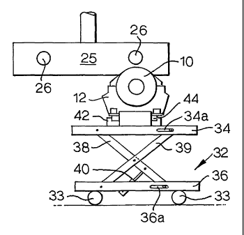
As shown in Figures 7 and 8, .the lifting device 32 has upper and lower
sections 34, 36 which are interconnected by means of scissor-like arms 38, 39.
The lower section 36 has castor wheels 33. The arms 38, 39 are pivotally
~5 connected to the upper and lower sections 34, 36 as clearly shown in Figure
8.
The upper ends of the arms 39 run in slots 34a in the upper section 34 and the
lower ends of arms 38 run in slots 36a in the lower section 36. A hydraulic
ram
40 is connected between the lower section 36 and the arms 38, 39 and is used
to raise and lower the upper section 34 of the lifting device 32. The upper
2o section 34 carries a roller table 42 on its upper surface. The roller table
42
comprises a plurality of freely rotatable rollers 44 arranged closely adjacent
each other in parallel fashion. The rollers 44 are of the same diameter and
lie in
a common plane. The holders 12 complete with the brakes 10 are removed
from the trolley 28 by means of a forklift truck 46, forks 48 of which locate
in the
25 openings 20 in the holder 12. The forklift truck 46 picks up one of the
holders 12
complete with its brake 10 and carries it to the lifting device 32 which is
placed
at a convenient position relative to the trolley 28. The forklift truck 46
deposits
the holder 12 so that the base plate 22 rests. on the roller table 42. Side
plates
50 are provided at sides of the roller table 42 to prevent the holder 12
rolling off
so the roller table 42. Also, safety clamps (not shown) are used to secure the
holder 12 in position on the roller table 42.
CA 02424804 2003-04-03
WO 02/30747 PCT/GBO1/04217
-7-
Once the holder 12 is in position on the lifting device 32 as shown in
Figure 7, the lifting device 32 is towed manually on its wheels 33 to a
position
immediately beneath the undercarriage leg 28. It viiill be noted from Figure 8
and 9 that the lifting device 28 is manoeuvred so as to position the brake 10
immediately beneath one of the axles 26 but spaced outwardly slightly beyond a
free end of the axle 26. The ram 40 is' then operated so as to cause the arms
38, 39 to pivot upwardly as shown in Figure 8 and thereby raise the upper
section 34 and the holder 12. Such lifting movement of the lifting device 32
is
continued until the cylindrical opening 24 in the brake 10 is aligned
coaxially
with the associated axle 26 as shown in Figure 9. It will also be noted from
Figure 9 that the holder 12 is positioned to one side of the roller table 42.
With
the brake 10 in the Figure 9 position an operator releases the safety clamps
and
then moves the holder 12 on the rollers 44 across the roller table 42 so that
the
brake 10 passes over the axle 26 with the axle 26 entering the cylindrical
opening 24. If required, the lifting device 32 can be moved on its wheels 33
so
as to cause the brake 10 to pass further over the axle 26 into its final
position.
The wheels 33 are unlocked for that purpose. Once the brake 10 is fully
supported by the axle 26, the brakes are locked in position in the usual way
so
that it is secured to the undercarriage leg 28. The strapping 16 is then
released
2o and the lifting device 32 is lowered so as to bring it back to the Figure 7
position. The empty holder 12 is then removed by the forklift truck 46 and the
next holder 12 complete with brake 10 is transferred by the forklift truck 46
from
the trolley 28 to the lifting device 32. The lifting device 32 is then
operated as
described above to enable the brake 10 to be located on the next axle 26. The
25 wheels 33 are then locked against turning. The procedure is continued until
brakes 10 are fully assembled on all four axles 26.
The next stage of the assembly is to mount undercarriage wheels 51 on
the brakes 10. The undercarriage wheels 51 are brought to the factory of the
aircraft manufacturer in the same way as the brakes 10 except that the wheels
so are located in a holder 52 shown in Figure 10. The holder 52 has~a
cylindrical
inner surface 54 defining a cradle which receives the wheel 51. A tyre 56 of
the
wheel 51 sits in the cradle and is retained therein by means of U-shaped side
CA 02424804 2003-04-03
WO 02/30747 PCT/GBO1/04217
_$_
plates 60.~ Instead of or in addition to using side plates, side arms (not
shown)
may be provided. Securing strapping 64 extends between eyes 66 so as to hold
the wheel 51 securely within its holder 52.
The holders 52 complete with wheels 51 are transported in the same way
as the brakes 10 as shown in Figures 1 to 5 and are finally deposited
individually on the roller table 44 of the lifting devicer32. They are secured
in
position on the roller table 44 by safety clamps (not shown). The lifting
device
32 is then positioned immediately beneath the undercarriage leg 28 as
described with respect to the brake 10 in Figure 7. The wheels 33 of the
lifting
device 32 are then locked against turning and the lifting device 32 is raised
as
described above so as to lift the holder 52 into the position shown in Figure
11,
where the wheel 51 is coaxial with the selected axle 26 and the brake 10
thereon. The safety clamps are removed and holder 52 is then pushed along
the roller table 44 so as to locate the brake 10 within the wheel 51. Again,
if
required, the lifting device can be moved on its wheels 33 so as to cause the
wheel 51 to ~be located fully on the brake 10. The wheels 33 are locked for
that
purpose. The wheel 5.1 is then bolted in position and the strapping 64 removed
to enable the lifting device to be lowered. The empty holder 52 with its wheel
51
is then removed by the forklift truck and a further holder 52 is deposited on
the
2o roller table 42. The procedure is continued until wheels 51 are mounted on
all
four axles 26.
The empty holders 12, 52 are loaded back on to their respective trolleys
28 and returned to the store 30. Once the next consignment of brakes/wheels
manufacturers delivered, the empty holders are collected by the brake/wheel
companies and returned for receiving the next batch of brakes/wheels.
It will be appreciated that the invention minimises manual handling of the
brakes and wheels and avoids the problems described in the introduction to the
specification.