Language selection

Search

Patent 2424920 Summary

Third-party information liability

Some of the information on this Web page has been provided by external sources. The Government of Canada is not responsible for the accuracy, reliability or currency of the information supplied by external sources. Users wishing to rely upon this information should consult directly with the source of the information. Content provided by external sources is not subject to official languages, privacy and accessibility requirements.

Claims and Abstract availability

Any discrepancies in the text and image of the Claims and Abstract are due to differing posting times. Text of the Claims and Abstract are posted:

  • At the time the application is open to public inspection;
  • At the time of issue of the patent (grant).
(12) Patent: (11) CA 2424920
(54) English Title: HELICOPTER ELECTRIC CONNECTING UNIT, AND HELICOPTER EQUIPPED WITH SUCH A CONNECTING UNIT
(54) French Title: DISPOSITIF DE CONNEXION ELECTRIQUE D'HELICOPTERE, ET HELICOPTERE EQUIPE DE CE DISPOSITIF DE CONNEXION
Status: Deemed expired
Bibliographic Data
(51) International Patent Classification (IPC):
  • B64D 47/00 (2006.01)
  • B64C 27/32 (2006.01)
  • B64C 27/82 (2006.01)
  • B64D 15/12 (2006.01)
  • H01R 39/08 (2006.01)
  • H01R 39/14 (2006.01)
(72) Inventors :
  • FABIANI, MARIO (Italy)
(73) Owners :
  • AGUSTA S.P.A. (Italy)
(71) Applicants :
  • AGUSTA S.P.A. (Italy)
(74) Agent: RIDOUT & MAYBEE LLP
(74) Associate agent:
(45) Issued: 2011-10-18
(22) Filed Date: 2003-04-09
(41) Open to Public Inspection: 2003-10-12
Examination requested: 2008-04-03
Availability of licence: N/A
(25) Language of filing: English

Patent Cooperation Treaty (PCT): No

(30) Application Priority Data:
Application No. Country/Territory Date
TO2002A 00330 Italy 2002-04-12

Abstracts

English Abstract

There is described an electric connecting unit for a helicopter, having a stator connected rigidly to a fixed part of the helicopter and fitted with first electric contact means; and a movable member rotated about a respective axis by a rotary member of the helicopter, and fitted with second electric contact means cooperating in sliding manner with the first electric contact means; the movable member having rigid fastening means for connection to the rotary member of the helicopter, so that no bearings are required between the stator and the movable member. (Figure 2)


French Abstract

La présente invention décrit un dispositif de connexion électrique pour un hélicoptère, muni d'un stator relié de manière rigide à une pièce fixe de l'hélicoptère et comportant un premier dispositif de contact électrique; le dispositif comprend également un élément mobile qui tourne sur un axe respectif sous l'action d'un élément rotatif de l'hélicoptère, l'élément mobile comportant un second dispositif de contact électrique, qui coulisse en coopération avec le premier dispositif de contact électrique; l'élément mobile comporte des fixations rigides pour le raccorder à l'élément rotatif de l'hélicoptère, de telle sorte que des roulements sont nécessaires entre le stator et l'élément mobile (Figure 2).

Claims

Note: Claims are shown in the official language in which they were submitted.


7


CLAIMS


1) A helicopter comprising a fixed part, at least
one rotary member rotating with respect to said fixed
part, and an electric connecting unit for connecting said
rotary member and said fixed part electrically; said
electric connecting unit comprising a stator connected
rigidly to said fixed part of the helicopter and having
first electric contact means; and a movable member
rotated about a respective axis by said rotary member and
having second electric contact means cooperating in
sliding manner with said first electric contact means;
wherein said movable member comprises rigid fastening
means for connection to said rotary member.


2) A helicopter as claimed in Claim 1, wherein said
stator and said movable member are mounted coaxially with
each other; and said movable member is interposed
radially between said stator and said rotary member.


3) A helicopter as claimed in Claim 2, wherein said
rigid fastening means comprise two bushes wedged tightly
between said rotary member and respective opposite end
portions of said movable member.


4) A helicopter as claimed in Claim 3, wherein said
rigid fastening means include a number of bolts for
gripping said bushes respectively to said end portions of
said movable member.


5) A helicopter as claimed in Claim 3 or 4, wherein
said end portions of said movable member are bounded


8


towards said rotary member by conical first surfaces
tapering towards each other; and said bushes are bounded
towards said movable member by conical second surfaces of
the same shape as said first surfaces and cooperating
with the first surfaces.


6) A helicopter as claimed in any one of Claims 1 to
5, wherein said stator is fixed rigidly to an outer
casing of a power transmission unit interposed between a
drive unit and a rotor of the helicopter; and said rotary
member is a shaft of said transmission unit.


7) A helicopter as claimed in any one of Claims 1 to
6, wherein said first electric contact means comprise a
number of radial contact blades; and said second electric
contact means comprise a number of annular conducting
tracks each cooperating in sliding manner with a
respective one of said contact blades.


Description

Note: Descriptions are shown in the official language in which they were submitted.


CA 02424920 2011-02-17

HELICOPTER ELECTRIC CONNECTING UNIT, AND HELICOPTER
EQUIPPED WITH SUCH A CONNECTING UNIT
The present invention relates to a helicopter electric connecting unit,
and to a helicopter equipped with such a connecting unit. More specifically,
in
s the following description, reference is made purely by way of example to an

electric connecting unit for connecting on-board instruments to a deicing
device on the helicopter tail rotor blades, or to test flight sensors for
determining rotor operating parameters.

Connecting units of the above type are known which substantially
io comprise an axially symmetrical stator having a number of radial contact
blades; and a movable member supported coaxially by the stator, rotated by
helicopter tail rotor actuating means, and having annular conducting tracks
which cooperate in sliding manner with the contact blades to connect the
stator and movable member electrically.

15 More specifically, the stator is normally fixed rigidly to an outer casing
of a power transmission unit interposed between the tail rotor hub and a drive
unit of the helicopter.

The movable member, on the other hand, is supported radially by the
stator by means of a number of bearings, and is rotated by a shaft of the tail
20 rotor transmission unit.

A major drawback of connecting units of the above type lies in
operating wear producing slack between the contacting components of the
bearings supporting the movable member, thus altering the relative positions
of the stator and movable member, and resulting in precarious, or even no,
25 electric connection between the conducting tracks and sliding contacts.

The present invention provides a helicopter electric connecting unit
designed to provide a straight forward, low-cost solution to the
aforementioned
drawback typically associated with known connecting units.


CA 02424920 2011-02-17
2

The present invention relates to a helicopter comprising a fixed part, at
least one rotary member rotating with respect to the fixed part, and an
electric
connecting unit for connecting the rotary member and the fixed part
electrically.
The electric connecting unit comprises a stator connected rigidly to the fixed
part

of the helicopter and having first electric contact means; and a movable
member
rotated about a respective axis by the rotary member and having second
electric
contact means cooperating in sliding manner with the first electric contact
means. The movable member comprises rigid fastening means for connection to
the rotary member.
A preferred, non-limiting embodiment of the present invention will be
described by way of example with reference to the accompanying drawings, in
which:

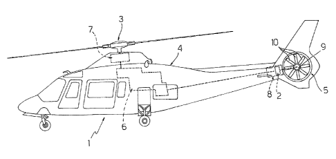
Figure 1 shows a schematic side view of a helicopter featuring a
is connecting unit in accordance with the present invention;

Figure 2 shows a larger-scale axial section of the electric connecting unit
according to the invention fitted to a transmission unit connected to the tail
rotor helicopter.


CA 02424920 2003-04-09

3
With reference to Figure 1, number 1 indicates as a whole a helicopter
having an electric connecting unit 2 (Figures 1 and 2) in accordance with the
present invention.
Helicopter 1 comprises, in known manner, a main rotor 3, fitted to an
intermediate top portion of the fuselage 4, and a secondary tail rotor 5, both
of which are powered by a drive unit 6 via respective transmission units 7, 8.
Connecting unit 2 is used to electrically connect the fixed part of
helicopter 1 and the movable parts - in the example shown, secondary rotor
5.
In the example shown, connecting unit 2 provides for connecting the
on-board instruments (not shown) to a deicing device (not shown) fitted to
secondary rotor 5, or to the test flight sensors for determining operating
parameters of secondary rotor 5.

As shown in Figure 1, secondary rotor 5 comprises a central hub 9
connected angularly by transmission unit 8 to an output member (not shown)
of drive unit 6; and a number of blades 10 fixed to and projecting radially
from
hub 9.

With reference to Figure 2, connecting unit 2 has an axis A, and is
mounted between an outer casing 11 of transmission unit 8, and a shaft 12 of
transmission unit 8, connected angularly to hub 9 of secondary rotor 5.

More specifically, connecting unit 2 substantially comprises a stator 15
connected rigidly, e.g. by screws (not shown), to casing 11 of transmission
unit 8, and having a number of contact blades 16; and a movable member 17
rotated about axis A by shaft 12, and having a number of side by side,

annular conducting tracks 18 cooperating in sliding manner with respective
contact blades 16.

Stator 15 is substantially in the form of a cylindrical sleeve, and
extends about shaft 12 with the interposition of movable member 17.


CA 02424920 2003-04-09

4
Stator 15 has two diametrically opposite, angular through openings 19
closed outwards by respective angular covers 20, each having a number of
contact blades 16 projecting radially from stator 15 towards movable member
17.
s More specifically, contact blades 16 of each cover 20 are arranged
side by side and aligned in a direction parallel to axis A.

An important aspect of the present invention is that movable member
17 is fixed rigidly to shaft 12 and interposed radially between shaft 12 and
stator 15.

io Movable member 17 is substantially in the form of a cylindrical sleeve
of axis A, and has conducting tracks 18 on a radially outer surface.

At opposite end portions 21, movable member 17 is bounded towards
shaft 12 by respective conical surfaces 22 tapering towards each other and
cooperating with respective bushes 23 wedged between movable member 17
15 and shaft 12.

More specifically, bushes 23 are fitted axially to shaft 12, and are
bounded, towards end portions 21 of movable member 17, by respective
conical surfaces 24 of the same shape as and cooperating with surfaces 22.

More specifically, bushes 23 have respective cross sections in the
20 form of rectangular trapeziums, the minor bases of which are positioned
facing each other and, like the major bases, extend radially with respect to
axis A, and the oblique sides of which are positioned contacting respective
surfaces 22 of movable member 17.

Bushes 23 are fitted tightly between shaft 12 and respective end
25 portions 21 of movable member 17 by means of a number of bolts 25 fitted
through respective through holes formed in movable member 17 and having
axes parallel to axis A.


CA 02424920 2003-04-09

More specifically, bolts 25 provide for gripping two annular members
27 fitted radially loosely to shaft 12 and cooperating end to end with
opposite
ends of movable member 17 and with respective bushes 23.

The advantages of helicopter 1 and electric connecting unit 2
5 according to the present invention will be clear from the foregoing
description.

In particular, by fitting movable member 17 rigidly and directly to shaft
12 of transmission unit 8, movable member 17 need no longer be supported
radially by stator 15 by means of bearings, which may therefore be

io dispensed with, so that the relative position of the component parts of
connecting unit 2 is more stable and less subject to wear.

Clearly, changes may be made to helicopter 1 and connecting unit 2
as described and illustrated herein without, however, departing from the
scope of the accompanying Claims.

Representative Drawing
A single figure which represents the drawing illustrating the invention.
Administrative Status

For a clearer understanding of the status of the application/patent presented on this page, the site Disclaimer , as well as the definitions for Patent , Administrative Status , Maintenance Fee  and Payment History  should be consulted.

Administrative Status

Title Date
Forecasted Issue Date 2011-10-18
(22) Filed 2003-04-09
(41) Open to Public Inspection 2003-10-12
Examination Requested 2008-04-03
(45) Issued 2011-10-18
Deemed Expired 2017-04-10

Abandonment History

There is no abandonment history.

Payment History

Fee Type Anniversary Year Due Date Amount Paid Paid Date
Application Fee $300.00 2003-04-09
Registration of a document - section 124 $100.00 2003-11-21
Maintenance Fee - Application - New Act 2 2005-04-11 $100.00 2005-04-05
Maintenance Fee - Application - New Act 3 2006-04-10 $100.00 2006-03-30
Maintenance Fee - Application - New Act 4 2007-04-09 $100.00 2007-03-13
Maintenance Fee - Application - New Act 5 2008-04-09 $200.00 2008-03-14
Request for Examination $800.00 2008-04-03
Maintenance Fee - Application - New Act 6 2009-04-09 $200.00 2009-03-18
Maintenance Fee - Application - New Act 7 2010-04-09 $200.00 2010-03-16
Maintenance Fee - Application - New Act 8 2011-04-11 $200.00 2011-03-15
Final Fee $300.00 2011-08-03
Maintenance Fee - Patent - New Act 9 2012-04-09 $200.00 2012-03-26
Maintenance Fee - Patent - New Act 10 2013-04-09 $250.00 2013-04-08
Maintenance Fee - Patent - New Act 11 2014-04-09 $450.00 2014-04-15
Maintenance Fee - Patent - New Act 12 2015-04-09 $250.00 2015-04-09
Owners on Record

Note: Records showing the ownership history in alphabetical order.

Current Owners on Record
AGUSTA S.P.A.
Past Owners on Record
FABIANI, MARIO
Past Owners that do not appear in the "Owners on Record" listing will appear in other documentation within the application.
Documents

To view selected files, please enter reCAPTCHA code :


To view images, click a link in the Document Description column. To download the documents, select one or more checkboxes in the first column and then click the "Download Selected in PDF format (Zip Archive)" or the "Download Selected as Single PDF" button.

List of published and non-published patent-specific documents on the CPD .

If you have any difficulty accessing content, you can call the Client Service Centre at 1-866-997-1936 or send them an e-mail at CIPO Client Service Centre.


Document
Description 
Date
(yyyy-mm-dd) 
Number of pages   Size of Image (KB) 
Abstract 2003-04-09 1 21
Description 2003-04-09 5 240
Claims 2003-04-09 2 121
Drawings 2003-04-09 2 62
Representative Drawing 2003-06-16 1 12
Cover Page 2003-09-16 1 40
Description 2011-02-17 5 199
Claims 2011-02-17 2 56
Cover Page 2011-09-12 1 42
Correspondence 2003-05-08 1 25
Assignment 2003-04-09 3 132
Assignment 2003-11-21 3 92
Fees 2005-04-05 1 28
Fees 2007-03-13 1 29
Fees 2006-03-30 1 27
Prosecution-Amendment 2008-04-03 1 33
Fees 2008-03-14 1 35
Fees 2009-03-18 1 36
Fees 2011-03-15 1 35
Prosecution-Amendment 2011-02-17 10 351
Prosecution-Amendment 2010-12-16 2 72
Fees 2010-03-16 1 36
Correspondence 2011-08-03 1 52
Fees 2013-04-08 2 55