Note: Descriptions are shown in the official language in which they were submitted.
CA 02424976 2004-08-31
METHOD OF ELECTROLYSIS OF WATER USING A HELICAL CATHODE
This invention relates to a method of electrolysis of water using a
helical cathode.
BACKGROUND OF THE INVENTION
Treatment of water and waste water by electro-coagulation is well
known as a process by which contaminant particles can be coagulated to form
precipitates which can be subsequently separated using conventional
flocculation,
settlement or filtration systems.
Conventional coagulation is a chemical process in which the charged
particles in colloidal suspension are neutralized by mutual collisions with
counter
ions. After the particle is neutralized, it will attract to other colloidal
particles and
agglomerate to form precipitates. It is generally accepted that coagulation
occurs
because of a reduction of the net surface charge of the particle to a point
where
electrostatic repulsive forces are reduced, then allowing van der Walls forces
to
dominate and allow particle agglomeration. Agglomerated particles could be
separated by a conventional separation technique such as settling
clarification tanks.
Chemicals have been used to coagulate contaminants in both water and waste
water treatment systems. These chemicals are not only costly; they also
contribute
secondary pollution to the environment.
Electro-coagulation is an electrical process in which a pair of
electrodes are used to neutralize small charged particles in colloidal
suspension.
The electrodes (anode and cathode) are subjected to a specific current
density.
Upon oxidation, the anodes are oxidized and form metal ions (either Fe+2 , Fe+
or
CA 02424976 2004-08-31
2
AI+3) in solution that react with hydroxide (OH-) anions created in the
electro
coagulation process. This leads to the formation of metal hydroxide ions,
either
cationic or anionic species depending on the pH of the waste water. A
combination
of inert anodes and metal (titanium) cathodes can also be used. The inert
electrodes accomplish pollutant destabilization utilizing the transfer of
electrons
within the electrolyte. The transfer of electrons and formation of protons
(H+)
created in the electro-coagulation process can effectively destabilize a range
of
metal and organic pollutant species.
Under appropriate conditions, various forms of charged hydroxyl (OH')
and AI+3 species might be formed. These gelatinous hydroxo cationic/anionic
complexes can effectively destabilize pollutants by adsorption and charge
neutralization by enmeshment of the particle, thus forcing it to react with a
counter
ion. Pollutants are also destabilized by ions of opposite charge (e- and p+)
produced
during electro-coagulation. Particles that undergoing destabilization, will
agglomerate due to the attractive van der Wall forces and form into a stable
precipitate which could then be separated by conventional separation
technique.
Typical chemical reactions at both the aluminium anode and cathode are shown
below:
Anode:
AI~S~ -~ AI3+~aq~ + 3e- (lose electrons)
A13+~aq~ + 3H20 ~ AI(OH)3+ 3H+
l7Al(OH)3 -~ AI"(OH)3n
Cathode:
CA 02424976 2004-08-31
3
2H20 + 2e- ~ Hz~g~ + 20H-
A13+ + 3e- ~ AI~S~ (gain electrons)
The electrochemical dissolution of the aluminum anode produces A13+
ions which further react with OH- ions (from cathode), transforming A13+ ion
initially
into AI(OH)3 and then into the gelatinous hydroxyl precipitate (AI"(OH)3").
Depending on the pH of the aqueous medium, different ionic species will also
be
formed in the medium such as: AI(OH)z+, Alz(OH)zz+, and AI(OH)4. At the
cathode,
hydrogen (Hz) gas and hydroxide (OH-) ions are formed from the division of H20
and
dissolved metals are reduced to their elemental state.(i.e. AI+3)
The electrochemical dissolution of the iron anode produces iron
hydroxide, Fe(OH)" where n = 2 or 3. There are two proposed mechanisms for the
production of the iron hydroxide. Like the gelatinous aluminum hydroxyl
precipitate
(AI"(OH)3"), the iron hydroxide precipitate (Fe(OH)") formed remains in the
aqueous
medium (stream) as a gelatinous suspension. This suspension can also remove
water and waste water contaminants either by complexation or by electrostatic
attraction, followed by coagulation. The cathode is subject to scale
formation, which
can impair the operation of the system. Typical chemical reactions at both the
iron
anode and cathode are shown below:
Anode:
4Fe~s~ ~ Fez+~aq~ + 8e- (lose electrons)
4Fez+~aq~ + 10H20~,~ + Ozcg> ~ 4Fe(OH)3~5~ + 8H+~aq)
Cathode:
8H+(aq) + 8e- ~ 4Hz(g)
CA 02424976 2004-08-31
4
Overall:
4Fe~s~ + 10H20~i~ +02~g> ~ 4Fe(OH)3~5~ + 4H2cg>
Anode:
Fe~s~ ~ Fe2+~aq~ + 2e- (lose electrons)
Fe2+~aq~ + 20H-~aq~ ~ FeOH2~s~
Cathode:
2Hz0~,~ +2e- ~ H2(e) + 20H-~aq~
Overall:
Fe~s~ + 2H20~p ~ Fe(OH)2~5~ + H2cg~
ELECTRO-COAGULATION TREATMENT (ECT) SYSTEMS
Utilizing electro-coagulation treatment (ECT) systems to treat waste
water was practised through most of the 20t" century with limited success.
Within
the last decade, technological advances in ECT systems has proved that it is
an
effective treatment method, brought on partially by increased environmental
regulations and environmental awareness. ECT is used to remove a variety of
water and waste water contaminants such as heavy metal ions (chromium, zinc,
silver) ,suspended solids and small colloids (greases and oils). Typically,
the ECT
system must have optimized operational parameters (pH, current density, and
temperatu re)
Examples of such electro-coagulation systems are shown in US Patent
6,139,710 (Powell) issued October 31, 2000, U.S. Patents 6,294,061 and
5,928,493
(Morkovsky) assigned to Kaspar Electroplating and issued September 25, 2001
and
CA 02424976 2004-08-31
July 27, 1999, and in US Patents 5,439,567 and 5,108,563 (Cook) assigned to
Environmental Systems and issued August 8, 1995 and April 28, 1992
respectively.
Many such systems use parallel plates as the necessary electrodes.
Cook discloses an arrangement in which a central rod forms an anode and the
5 cathode is defined by a surrounding sleeve which is perforated with a series
of holes
so as to allow the water to enter the area inside the cylindrical cathode so
as to be
acted upon between the anode and the cathode.
One significant problem which arises with continuous flow ECT
systems is treating a sufficient rate of flow of water and waste water at
reasonable
cost, while at the same time preventing the system from clogging due to the
formation of precipitates and corrosion scale deposited on the cathode.
It is essential therefore for continuous flow that the arrangement of the
cathode and anode, herein referred to as the electrolytic cell, be in effect
self-
cleaning in that the flow of liquid is sufficient to carry with it the
coagulated
precipitates while allowing treatment of the liquid at a sufficient efficiency
to remove
the contaminants.
Up till now there has been no suitable design of an electrolytic cell
which provides an adequate treatment of the water and waste water to
continuously
remove the contaminants while at the same time preventing fowling of the cell.
Once fowling commences, this builds up until the cell becomes clogged. There
is at
this time no effective way to self-clean the cell once the coagulation of
particles has
commenced. While electro-coagulation is therefore known and accepted in
CA 02424976 2004-08-31
6
principle, its commercial continuous flow application has been limited by this
problem.
SUMMARY OF THE INVENTION
It is one object of the present invention to provide an improved electro-
coagulation treatment (ECT) system for removing contaminants from water and
waste water and primarily to provide a novel electrolytic cell construction
therefor.
According to a first aspect of the invention there is provided a method
for electro-coagulation treatment of contaminated water or waste water
containing
contaminant particles comprising:
providing an electrolytic cell including an anode and a helical cathode;
causing the water containing contaminant particles to come into
contact with the cell;
applying a DC voltage across the anode and cathode of the cell so as
to cause a current flow through the water so as to cause coagulation of the
contaminant particles in the water;
and extracting the coagulated precipitates from the water;
providing the anode in the form of a central longitudinal member
defining an outer anode surface surrounding the axis and extending along an
axis of
the cell;
and providing the cathode in the form of a helical cathode which
comprises an elongate member coiled helically around and along the anode so as
to
form a plurality of turns of the elongate member which turns are wrapped
around the
CA 02424976 2004-08-31
7
anode surface, are spaced each from the next and are spaced from the anode
surface.
Preferably the turns are of equal diameter so that the turns lie in a
circular cylindrical shape surrounding the anode surface. However it is not
essential
that either the anode or the helical cathode are of constant diameter along
their
length and other varying shapes may be employed if required.
Preferably the turns are equally spaced each from the next to form a
helix of constant pitch. However variations in pitch are also possible to
accommodate changes in voltage along the cell or to provide different current
density at required different locations in the cell.
Preferably the anode surface is circular cylindrical in shape and is
formed from a rod of a suitable sacrificial material such as iron or aluminum.
Preferably the elongate member forming the helical cathode is circular
in cross-section and is of constant cross section.
Preferably the cell is located longitudinally within a duct and the water
or waste water is caused to flow along the duct. In this arrangement, the
helical
cathode is spaced from an inside surface of the duct such that the water is
caused to
flow between the helical cathode and the anode and between the helical cathode
and the inside surface. Preferably the helical cathode is spaced from an
inside
surface of the duct by a plurality of spacers arranged at specific angular
locations
around the helical cathode and duct attached to the helical cathode so as to
bridge
at least two turns of the elongate member.
CA 02424976 2004-08-31
However the cell can also be used in some cases with transverse flow
or by simple immersion within water contained within a settlement tank.
In most cases, the electrolytic cell causes electro-coagulation of the
contaminants in the water and waste water so that the treated effluent and
coagulated precipitates are transferred from an outlet of the duct to a
flocculation or
clarification tanks where the coagulated precipitates are separated.
Separation can
be effected simply by settlement in a suitable settling tank or may be
accelerated by
use of well know flocculating agents.
When flowing through the cell within a duct, a portion of the water and
coagulated contaminant particles is optionally returned from the outlet of the
duct to
an inlet of the duct to maintain a predetermined flow through the duct.
Preferably each end of the anode and each end of the elongate
member forming the cathode is connected to a source of DC voltage so that the
voltage along the length of the cell and thus the current density in the cell
is
maintained as constant as possible without significant drop off at one end of
the cell.
The current density necessary to effect the necessary treatment on
the contaminants in the water varies widely depending upon many factors
including
the amount of contaminants, the type of contaminants, the removal
efficiencies, the
rate of flow and the characteristics of the water and waste water. The size of
the
anode and the dimensions of the cathode thus can vary widely dependent upon
these characteristics and the necessary trials to determine a particularly
suitable
construction for particular characteristics can be readily determined by
simple trial.
However the following dimensions are provided as to typical characteristics:
CA 02424976 2004-08-31
9
Preferably, the diameter of the anode lies in the range of 25 mm to 300
mm..
Preferably, the diameter of the elongate member forming the cathode
lies in the range of 3 mm to 25 mm.
Preferably, the spacing between the anode and the cathode lies in the
range of 2 mm to 10 mm.
Preferably, the spacing between the turns of the elongate member
forming the cathode lies in the range of 2 mm to 20 mm.
Preferably, the current density lies in the range of 50 watts to 2000
watts.
It is a second different object of the present invention to provide a
method by which the electrolysis of the water generates hydrogen which is
collected.
According to a second aspect of the invention there is provided a
method comprising:
providing an electrolytic cell including an anode and a helical cathode;
causing water containing contaminant particles to come into contact
with the cell;
applying a DC voltage across the anode and cathode of the cell so as
to cause a current flow through the water to form hydrogen gas at the cathode;
collecting the hydrogen gas;
the application of the DC voltage across the anode and cathode of the
cell being arranged to cause coagulation of the contaminant particles in the
water;
extracting the coagulated precipitates from the water;
CA 02424976 2004-08-31
providing the anode in the form of a central longitudinal member
defining an outer anode surface surrounding the axis and extending along an
axis of
the cell;
and providing the cathode in the form of a helical cathode which
5 comprises an elongate member coiled helically around and along the anode so
as to
form a plurality of turns of the elongate member which turns are wrapped
around the
anode surface, are spaced each from the next and are spaced from the anode
surface.
BRIEF DESCRIPTION OF THE DRAWINGS
10 One embodiment of the invention will now be described in conjunction
with the accompanying drawings in which:
Figure 1 is a schematic illustration of an electrolytic cell for use in a
electro-coagulation treatment (ECT) t system.
Figure 2 is a view of one portion of Figure 1 on an enlarged scale.
Figure 3 is a block diagram showing the components of the ECT
system.
In the drawings like characters of reference indicate corresponding
parts in the different figures.
DETAILED DESCRIPTION
It has been found surprisingly that the provision of a helical cathode in
the form of a helically wound coil of a wire or rod of circular cross section
provides
an arrangement in which the cell is automatically self cleaning in that the
coagulated
precipitates are carried from the cell by the flow of the water. At the same
time the
CA 02424976 2004-08-31
11
arrangement provides an adequate level of treatment of the contaminated water
and
waste water to provide the necessary coagulation by which the coagulated
precipitates can be subsequently extracted using conventional flocculation,
settlement or filtration systems.
In Figure 3 is shown the electro-coagulation treatment (ECT) system
for water and waste water supplied from a supply indicated at RAW and the
water
passes through the treatment path to a discharge of treated water indicated at
TREATED.
The ECT system includes the electrolytic t cell 2 which is powered by a
DC power supply 1. A supply pump 5 pumps the water from the source under
pressure through a valve 13 and a flow meter 6 into one end of the reaction
chamber
2 containing the cell. Thus the pumped contaminated water enters a lower end
2A
of the reaction chamber and departs an upper end 2B of the reaction chamber.
From the upper end of the reaction chamber, the water containing the
contaminants
is carried under pump pressure through the pressure gauge 7 and a valve 11 to
a
de-gasifier 8, a mixing chamber 9 and a clarification chamber 10. The de-
gasifier 8
includes a vent by which gas, generally hydrogen, generated in the treatment
can be
discharged to atmosphere or to collection if required.
In the mixing chamber 9 can be added conventional flocculating agents
from a supply S for mixing with the electro-coagulated water and waste water
within
the mixing chamber 9. After mixing the coagulated precipitates and
flocculating
agents are supplied to a larger collection and settling chamber 10 in which
CA 02424976 2004-08-31
12
clarification occurs by settlement supplying treated water and effluent in a
treated
stream and sludge in a sludge stream.
The de-gasifier, mixing chamber and clarification system are of a
conventional nature. Other methods known to one skilled in the art can be
provided
for extracting the coagulated precipitates from the treated stream such as
conventional flocculation, settlement or filtration systems. Conventional
techniques
can be provided for de-watering and drying the sludge.
In many cases the sludge from an electro-coagulation treatment (ECT)
system treating an industrial waste water is non-hazardous so that it can
simply be
discarded in a municipal landfill. The contents and nature of the sludge of
course
depend upon the contaminants within the water and waste water supply stream.
Preliminary test results from the ECT system shown in Figure 3 show that the
sludge
containing high concentrations of chromium contaminants are non-hazardous,
having passed the Canadian General Standards Board (CGSB) Leachate Procedure
(EPA SW-846 Method 1310A L). However heavy metal contaminants such as
chromium are often extracted into a sludge which is non-hazardous due to the
chemical action within the electrolytic cell, which is itself well known to
one skilled in
the art.
In order to maintain a constant flow through the reaction chamber 2
despite potential variation in supply rate through the pump 5, there is
provided a re-
cycle pump 3 in a line parallel to the reaction chamber and carrying recycle
materials
from the upper outlet 2B back to the inlet 2A of the reaction chamber. The
pumps 3
CA 02424976 2004-08-31
13
and 5 are controlled by a control unit 4 to maintain the required constant
flow of the
contaminated and recycled water over the cell within the reaction chamber.
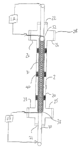
Turning now to Figures 1 and 2, the electrolytic cell construction is
shown in detail. This comprises a chamber 2 in the form of a pipe 20 having
closed
ends 21 and 22. Adjacent the end 21 is provided a pair of right angle
couplings 23
and 25 and adjacent the end 22 is provided a similar pair of right angle
couplings 24
and 26. Each of the couplings 23 and 24 is plugged. The coupling 25 provides
the
inlet 2A and the coupling 26 provides the outlet 2B. Thus water and waste
water to
be treated enters the coupling 25 and passes along the pipe 20 to the coupling
26.
An anode 30 in the form of an elongate rod passes through the plugs 21 and 22
and
thus lies in fixed position along the axis of the pipe 20. The anode is formed
from a
suitable sacrificial material such as iron, aluminum, or the like which
provides ions in
an electrolytic action when a voltage is applied between the anode and the
cathode.
The helical cathode is formed by a helical coil of wound wire. The wire
is carefully wound to form a helix of constant diameter and constant pitch so
that the
wire turns are spaced each from the next. The inside diameter of the helix is
such
that it is spaced from the cylindrical outside surface of the anode 30. The
outside
diameter of the helix is such that it is spaced from the inside surface of the
pipe 20.
The helix 31 is continuous from an upper end 32 to a lower end 33.
The upper end 31 is aligned with the right angled connector 24 so that an end
of the
wire forming the helix extends through the plug in the connector 24 to provide
an
exposed portion outside the chamber. Similarly the lower end of the wire at
the
lower end 33 extends through the compression fitting in the connector 23.
CA 02424976 2004-08-31
14
The power supply 1 includes two separate power supply components
each generating a predetermined voltage difference which is applied across the
respective ends of the anode and cathode. Thus a power supply portion 1A
applies
a voltage between the upper end of the anode 30 and the upper end of the
helical
cathode. Similarly the power supply portion 1 B provides a voltage across the
lower
end of the anode 30 and the exposed lower end of the cathode.
The length of the anode and the cathode and thus the length of the
pipe 20 between the connectors is arranged so that the voltage across the
anode
and cathode along the full length thereof remains substantially constant or at
least
does not drop to a level at which the current density is insufficient to
effect proper
water treatment.
The helix is supported within the pipe 20 by a plurality of spacers 40.
The spacers are formed by short lengths of wire which are welded parallel to
the
axis of the helix at angularly spaced positions around the helix so that each
spacer is
welded to 2 or more turns of the helix. Thus the helix is held against
longitudinal
spring action and is also held against side to side movement. The spacers have
a
diameter sufficient that they are in sliding fit with the inside surface of
the pipe.
Generally four such spaces are used around the axis at 90° spacing
so as to
maintain the helix centered around the axis of the pipe. However the spacers
do not
interfere with the longitudinal flow of water along the pipe both inside the
helix and
outside the helix. The number of spacers along the length of the helix depends
upon
the length of the helix and the number of turns and the gauge of the wire used
to
CA 02424976 2004-08-31
form the helix but as shown there are four sets of spacers arranged at axially
spaced
positions along the length of the helix.
As set forth hereinbefore, the operation of the cell is to cause electro-
coagulation of the contaminants within the water while at the same time
ensuring
5 that all of the particles so coagulated are carried in the stream out of the
cell and out
of the outlet 2B for further treatment. It has been surprisingly found that
the
construction of cells set forth above in which the water can flow both outside
and
inside the helical cathode provides adequate treatment of the contaminants
while at
the same time ensuring that no coagulated particles commence to collect at any
10 point within the cell.
It is believed that the helical formation of the cathode at which the
particles would normally collect ensures that there are no surfaces with
suitable sites
for collection to commence since the whole length of the cathode is formed
from a
continuous wire wound into helical form. At the same time the wire, even
though it
15 leaves spaces between the turns, provides adequate treatment of the water
in the
electrolytic action. The water and waste water acts as an electrolyte between
the
anode and cathode in the cell which in turn allows for the formation of the
coagulated precipitates.
Preliminary ECT Pilot Plant Study Results
A pilot plant study utilizing the electro-coagulation treatment system
(ETS) described in Figure 3 was undertaken to treat a chromic acid rinse waste
water. The pilot study involved the on-site pre-treatment of approximately
10,000
litres of this industrial waste water. The primary goal of the pilot plant
study was to
CA 02424976 2004-08-31
16
optimize and evaluate a new continuous-flow electro-coagulation treatment
system
(ETS) in removing Chromium to levels below 5 mg/L in the treated effluent.
Specific
objectives include: (1) to optimize the ETS at various influent flow rates and
re-
circulation flow rates; and (2) to determine average heavy metal removal
efficiencies
.The experimental treatment trials include recirculation (Trials 1 and 2) and
non-
recirculation (Trials 3 and 4)
I. EXPERIMENTAL TREATMENT TRIAL 1
A. System Parameters
1. The inlet flow rate was set at 9L/min.
2. The re-circulation flow rate was set at 9L/min.
3. Total treatment time for Trial 1 was 2.5 hours.
B. pH and Temperature Results
1. The raw waste water temperature was 18 degrees C
2. The rapid mix chamber temperature was 20 degrees C
3. The slow mix chamber temperature was 20 degrees C
4. The settling tank temperature after 2 hours was 20 degrees C
5. The raw waste water pH was 7.6
6. The waste water pH in the rapid mix chamber was 8.3
7. The waste water pH in the slow mix chamber was 8.4
8. The waste water pH in the settling tank was 8.3
Heavy Metal Analysis Results
Parameter JR #1 (raw) Units ETS-1 % Removal Date Analyzed
CA 02424976 2004-08-31
17
Efficiency
Aluminum 3.6 mg/I 0.08 97.8 Sept.30/02
Antimony 0.01 mg/I 0.005 50.0 Sept.30/02
Arsenic 0.0247 mg/I 0.0021 91.5 Sept.30/02
Barium 0.0431 mg/I 0.0012 97.2 Sept.30/02
Beryllium < 0.001 mg/I < 0.001 N/A Sept. 30/02
Bismuth 0.0003 mg/I < 0.0001 N/A Sept. 30/02
Boron 1.62 mg/I 1.35 16.7 Sept.30/02
Cadmium 0.0071 mg/I 0.0003 95.8 Sept.30/02
Calcium 30.5 mg/I 5.6 81.6 Sept.30/02
Cesium 0.0004 mg/I 0.0002 50.0 Sept.30/02
Chromium 86.8 mg/I 1.03 98.8 Sept.30/02
Cobalt 0.0109 mg/I 0.0028 74.3 Sept.30/02
Copper 0.384 mg/I 0.034 91.1 Sept.30/02
Iron 1.64 mg/I 1.48 9.8 Sept.30/02
Lead 0.102 mg/I 0.0015 98.5 Sept.30/02
Lithium 0.01 mg/I < 0.01 N/A Sept. 30/02
Magnesium 6.26 mg/I 2.55 59.3 Sept.30/02
Manganese 0.638 mg/I 0.0331 94.8 Sept.30/02
Mercury 0.0004 mg/I N/A Sept.30/02
Molybdenum 0.0228 mg/I 0.0445 N/A Sept.30/02
Nickel 0.094 mg/I 0.039 58.5 Sept.30/02
CA 02424976 2004-08-31
18
Phosphorus11.6 mg/I 0.27 97.7 Sept.30/02
Potassium 102 mg/I 98 3.9 Sept.30/02
Rubidium 0.0161 mg/I 0.0153 5.0 Sept.30/02
Selenium < 0.001 mg/I < 0.001 N/A Sept. 30/02
Silver 0.001 mg/I < 0.001 N/A Sept. 30/02
Sodium 122 mg/I 117 4.1 Sept.30/02
Strontium 0.162 mg/I 0.0151 90.7 Sept.30/02
Tellurium < 0.001 mg/I < 0.001 N/A Sept. 30/02
Thallium < 0.0001 mg/I < 0.0001 N/A Sept. 30/02
Tin- Total0.0045 mg/I 0.0018 60.0 Sept. 30/02
Titanium 0.128 mg/I 0.0031 97.6 Sept.30/02
Tungsten 0.0157 mg/I 0.0093 40.8 Sept.30/02
Uranium 0.0004 mg/I 0.0001 75.0 Sept.30/02
Vanadium < 0.001 mg/I < 0.001 N/A Sept. 30/02
Zinc 0.49 mg/I 0.05 89.8 Sept.30/02
Zirconium 0.0751 mg/I 0.0069 90.8 Sept.30/02
pH 7.6 8.3 Sept. 30/02
II. EXPERIMENTAL TREATMENT TRIAL 2
A. System Parameters
1. The inlet flow rate was set at 9L/min.
2. The re-circulation flow rate was set at 9L/min.
CA 02424976 2004-08-31
19
3. The total treatment time for trial 2 was 2:45 hours.
B. pH and Temperature Results
1. The raw waste water temperature was 19 degrees C
2. The rapid mix chamber temperature was 21 degrees C
3. The slow mix chamber temperature was 21 degrees C
4. The settling tank temperature after 2 hours was 21 degrees C
5. The raw waste water pH was 7.6
6. The waste water pH in the rapid mix chamber was 8.6
7, The waste water pH in the slow mix chamber was 8.5
8. The waste water pH in the settling tank was 8.2
C. Heavy Metal Analysis Results
Parameter JR #1 Units ETS-2 % Removal Date Analyzed
(raw) Efficiency
Aluminum 3.6 mg/I 0.21 94.2 Oct.2/02
Antimony 0.01 mg/I 0.006 40.0 Oct.2/02
Arsenic 0.0247 mg/I 0.0025 89.9 Oct.2/02
Barium 0.0431 mg/I 0.0027 93.7 Oct.2/02
Beryllium < 0.001 mg/I < 0.001 N/A Oct. 2/02
Bismuth 0.0003 mg/I < 0.0001 N/A Oct. 2/02
Boron 1.62 mg/I 1.33 17.9 Oct.2/02
Cadmium 0.0071 mg/I 0.0009 87.3 Oct.2/02
Calcium 30.5 mg/I 6.2 79.7 Oct.2/02
CA 02424976 2004-08-31
Cesium 0.0004 mg/l 0.0002 50.0 Oct.2/02
Chromium 86.8 mg/I 0.436 99.5 Oct.2/02
Cobalt 0.0109 mg/I 0.0023 78.9 Oct.2/02
Copper 0.384 mg/I 0.042 89.1 Oct.2/02
Iron 1.64 mg/I 1.16 29.3 Oct.2/02
Lead 0.102 mg/I 0.0075 92.6 Oct.2/02
Lithium 0.01 mg/I < 0.01 N/A Oct. 2/02
Magnesium 6.26 mg/I 3.74 40.3 Oct.2/02
Manganese 0.638 mg/I 0.0363 94.3 Oct.2/02
Mercury 0.0004 mg/I N/A Oct.2/02
Molybdenum 0.0228 mg/I 0.0417 N/A Oct.2/02
Nickel 0.094 mg/l 0.045 52.1 Oct.2/02
Phosphorus 11.6 mg/I 0.24 97.9 Oct.2/02
Potassium 102 mg/I 100 2.0 Oct.2/02
Rubidium 0.0161 mg/I 0.0156 3.1 Oct.2/02
Selenium < 0.001 mg/I < 0.001 N/A Oct. 2/02
Silver 0.001 mg/I 0.005 N/A Oct.2/02
Sodium 122 mg/I 124 N/A Oct.2/02
Strontium 0.162 mg/I 0.0164 89.9 Oct.2/02
Tellurium < 0.001 mg/I < 0.001 N/A Oct. 2/02
Thallium < 0.0001 mg/I < 0.0001 N/A Oct. 2/02
Tin- Total 0.0045 mg/I 0.0033 26.7 I Oct. 2/02
~
CA 02424976 2004-08-31
21
Titanium 0.128 mg/I 0.0036 97.2 Oct.2/02
Tungsten 0.0157 mg/I 0.0078 50.3 Oct.2/02
Uranium 0.0004 mg/I 0.0001 75.0 Oct.2/02
Vanadium < 0.001 mg/I < 0.001 N/A Oct. 2/02
Zinc 0.49 mg/l 0.08 83.7 Oct.2/02
Zirconium 0.0751 mg/I 0.0026 96.5 Oct.2/02
pH 7.6 8.2 Oct. 2/02
III. EXPERIMENTAL TREATMENT TRIAL 3
A. S~istem Parameters
1. The inlet flow rate was set at 9Umin.
2. The total treatment time for trial 3 was 2:52 hours.
B. aH and Temperature Results
1. The raw waste water temperature was 17.5 degrees C
2. The rapid mix chamber temperature was 19.5 degrees C
3. The slow mix chamber temperature was 19.5 degrees C
4. The settling tank temperature after 2 hours was 18 degrees C
5. The raw waste water pH was 7.6
6. The waste water pH in the rapid mix chamber was 8.4
7. The waste water pH in the slow mix chamber was 8.4
8. The waste water pH in the settling tank was 8.3
9. The waste water pH in the settling tank after 2 hours was 8.3
CA 02424976 2004-08-31
22
10. The pH of the decant from the settling tank was?
11.The conductivity of the raw waste water was 0.95mS/cm
12. The conductivity of the treated effluent was 0.90mS/cm
C. Heavy Metal Analysis Results
Parameter JR #1 (raw)Units ETS-3 % Removal Date Analyzed
Efficiency
Aluminum 3.6 mg/I 0.05 98.6 Oct.9/02
Antimony 0.01 mgll 0.004 60.0 Oct.9/02
Arsenic 0.0247 mg/I 0.0028 88.7 Oct.9/02
Barium 0.0431 mg/I 0.0011 97.4 Oct.9/02
Beryllium < 0.001 mg/l < 0.001 N/A Oct. 9/02
Bismuth 0.0003 mg/I 0.0001 N/A Oct.9/02
Boron 1.62 mg/I 1.35 16.7 Oct.9/02
Cadmium 0.0071 mg/I 0.0003 95.8 Oct.9/02
Calcium 30.5 mg/I 6 80.3 Oct.9/02
Cesium 0.0004 mg/I 0.0001 75.0 Oct.9/02
Chromium 86.8 mg/I 0.914 98.9 Oct.9/02
Cobalt 0.0109 mg/I 0.0022 79.8 Oct.9/02
Copper 0.384 mg/I 0.035 90.9 Oct.9/02
Iron 1.64 mg/I 1.5 8.5 Oct.9/02
Lead 0.102 mg/I 0.0005 99.5 Oct.9/02
Lithium 0.01 mg/I < 0.01 N/A Oct. 9/02
CA 02424976 2004-08-31
23
Magnesium 6.26 mg/I 3.06 51.1 Oct.9/02
Manganese 0.638 mg/I 0.0347 94.6 Oct.9/02
Mercury 0.0004 mg/I N/A N/A Oct.9/02
Molybdenum 0.0228 mg/I N/A Oct.9/02
Nickel 0.094 mg/I 0.041 56.4 Oct.9/02
Phosphorus 11.6 mg/I 0.2 98.3 Oct.9/02
Potassium 102 mg/I 103 N/A Oct.9/02
Rubidium 0.0161 mg/I 0.0156 3.1 Oct.9/02
Selenium < 0.001 mg/I < 0.001 N/A Oct. 9/02
Silver 0.001 mg/I < 0.001 N/A Oct. 9/02
Sodium 122 mg/I 127 N/A Oct.9/02
Strontium 0.162 mg/I 0.0016 99.0 Oct.9/02
Tellurium < 0.001 mg/I < 0.001 N/A Oct. 9/02
Thallium < 0.0001 mg/I < 0.0001 N/A Oct. 9/02
Tin- Total 0.0045 mg/I 0.0005 88.9 Oct. 9/02
Titanium 0.128 mg/I 0.0005 99.6 Oct.9/02
Tungsten 0.0157 mg/I 0.0069 56.1 Oct.9/02
Uranium 0.0004 mg/I 0.0001 75.0 Oct.9/02
Vanadium < 0.001 mg/I < 0.001 N/A Oct. 9/02
Zinc 0.49 mg/I 0.03 93.9 Oct.9/02
Zirconium 0.0751 mg/I 0.0039 94.8 Oct.9/02
pH 7.6 Oct. 7/02
CA 02424976 2004-08-31
24
IV. EXPERIMENTAL TREATMENT TRIAL 4
A. System Parameters
1. The inlet flow rate was set at 9L/min.
2. The total treatment time for trial 4 was 2:36 hours.
B.~H and Temperature Results
1. The raw waste water temperature was 16.5 degrees C
2. The rapid mix chamber temperature was 18.5 degrees C
3. The slow mix chamber temperature was 18.5 degrees C
4. The settling tank temperature after 2 hours was 18.5 degrees C
5. The raw waste water pH was 7.6
6. The waste water pH in the rapid mix chamber was 8.4
7. The waste water pH in the slow mix chamber was 8.4
8. The waste water pH in the settling tank was 8.4
9. The waste water pH in the settling tank after 2 hours was 8.4
10. The pH of the decant from the settling tank was?
C. Hea_v~~ Metal Analysis Results
Parameter Raw Units ETS-4 % Removal Date Analyzed
Efficiency
Aluminum 3.6 mg/I 0.04 98.9 Oct.17/02
Antimony 0.01 mg/I 0.005 50.0 Oct.17/02
Arsenic 0.0247 mg/I 0.0026 89.5 Oct.17/02
CA 02424976 2004-08-31
Barium 0.0431 mg/I 0.0016 96.3 Oct.17/02
Beryllium < 0.001 mg/I < 0.001 NlA Oct. 17/02
Bismuth 0.0003 mg/I 0.0001 N/A Oct.17/02
Boron 1.62 mg/l 1.26 22.2 Oct.17/02
Cadmium 0.0071 mg/I 0.0002 97.2 Oct.17/02
Calcium 30.5 mg/I 6.8 77.7 Oct.17/02
Cesium 0.0004 mg/I 0.0001 75.0 Oct.17/02
Chromium 86.8 mg/I 0.465 99.5 Oct.17/02
Cobalt 0.0109 mgll 0.0021 80.7 Oct.17/02
Copper 0.384 mg/I 0.033 91.4 Oct.17/02
Iron 1.64 mg/I 0.99 39.6 Oct.17/02
Lead 0.102 mg/I 0.0011 98.9 Oct.17/02
Lithium 0.01 mg/I < 0.01 N/A Oct. 17/02
Magnesium 6.26 mg/I 3.25 48.1 Oct.l7/02
Manganese 0.638 mg/I 0.0243 96.2 Oct.17/02
Mercury 0.0004 mg/I N/A N/A Oct.17/02
Molybdenum 0.0228 mg/I 0.0373 N/A Oct.17/02
Nickel 0.094 mg/I 0.038 59.6 Oct.17/02
Phosphorus 11.6 mg/I 0.23 98.0 Oct.17/02
Potassium 102 mg/I 97.2 N/A Oct.17/02
Rubidium 0.0161 mg/I 0.0144 10.6 Oct.17/02
Selenium < 0.001 mg/I < 0.001 N/A Oct. 17/02
CA 02424976 2004-08-31
26
Silver 0.001 mg/I < 0.001 N/A Oct. 17/02
Sodium 122 mg/I 122 0.0 Oct.17/02
Strontium 0.162 mg/I 0.0136 91.6 Oct.17/02
Tellurium < 0.001 mg/I < 0.001 N/A Oct. 17/02
Thallium < 0.0001 mg/I < 0.0001 N/A Oct. 17/02
Tin- Total 0.0045 mg/I 0.0026 42.2 Oct. 17/02
Titanium 0.128 mg/I 0.0023 98.2 Oct.17/02
Tungsten 0.0157 mg/I 0.0066 58.0 Oct.17/02
Uranium 0.0004 mg/I 0.0001 75.0 Oct.17/02
Vanadium < 0.001 mg/I < 0.001 N/A Oct. 17/02
Zinc 0.49 mg/I 0.05 89.8 Oct.17/02
Zirconium 0.0751 mg/I 0.0026 96.5 Oct.17/02
pH 7.6 8.4 Oct. 16/02
Since various modifications can be made in my invention as herein
above described, and many apparently widely different embodiments of same made
within the spirit and scope of the claims without departing from such spirit
and
scope, it is intended that all matter contained in the accompanying
specification shall
be interpreted as illustrative only and not in a limiting sense.