Note: Descriptions are shown in the official language in which they were submitted.
CA 02425012 2003-04-04
WO 02/31750 PCT/KRO1/01499
IRIS IDENTIFICATION SYSTEM AND METHOD AND COMPUTER
READABLE STORAGE MEDIUM STORED THEREIN COMUPTER
EXECUTABLE INSTRUCTIONS TO IMPLEMENT IRIS IDENTIFICATION
METHOD
s
TECHNICAL FIELD
A present invention relates to an iris- recognition technology for
identifying person and, in particular, to an iris identification system and
method,
and a computer readable storage medium stored therein computer executable
1o instructions to implement the iris identification method, that are capable
of
improving an iris recognition accuracy using reference iris images, per
person,
taken in various environments.
BACKGROUND ART
Recently, various biometric identification technologies using fingerprint,
Is voice, iris, and vein patterns have been developed. Among them, the iris
identification technology is known to provide the most secure identification
reliability in the security field.
Such an iris identification technology is well known in the art as
disclosed by International Publication No. W094/9446 entitled "Biometric
2o Personal Identification System Based On Iris Analysis."
This prior art discloses the iris identification technique which is
performed in such a way of acquiring an image of the eye to be analyzed in
digital form suitable for analysis, defining and isolating the iris portion of
the
image, analyzing the defined area of the image so as to produce an iris code,
2s storing the iris code as a reference code, and comparing a presented code
with
i
CA 02425012 2003-04-04
WO 02/31750 PCT/KRO1/01499
the reference code to obtain a Hamming distance through the exclusive-OR
logical operation. The Hamming distance is used in order to determine the
identity of a person and to calculate confidence level for the decision.
However, this prior art has some drawbacks in that it is difficult to
consistently adopt the polar coordinates system to the iris identification
since
the pupil 2 is constricted when exposed to bright light and expanded in dim
light
(see FiG. 1a) and the constriction/expansion degree to the light differs in
every
person because each person has his/her own characteristics in sphincter
pupillae, dilator pupillae, intraocular pressure, and etc., such that it is
also
1o difficult to predict how an iris characteristic factor of the iris 1
changes when the
pupil 2 expands (see FIG. 1 b). Referring to FIG. 1 b, when an iris image
having
a characteristic factor 3 is presented and compared with one of the reference
images, it might be determined that there is no identical reference image.
Also, since the iris identification of the prior art divides the iris image so
15 as to define annular analysis portions, this identification accuracy
considerably
decreases when this technique is used for Asian people whose eye is exposed
a little relative to the westerners. If narrowing the analysis band in order
to
prevent this problem, security reliability is seriously degraded.
Furthermore, this prior art iris identification technique has no algorithm
2o capable of preventing misidentification by an inorganic fake iris.
DISCLOSURE OF INVENTION
The present invention has been made in an effort to solve the above
problems of the prior art.
2
CA 02425012 2003-04-04
WO 02/31750 PCT/KRO1/01499
It is an object of the present invention to provide an iris identification
system and method capable of reducing misidentification rate by taking several
reference iris images captured from one iris in various luminance environments
and repeatedly comparing a presented iris data to each of the reference iris
images.
It is another object of the present invention to provide an iris
identification system and method capable of reducing analysis denial rate
regardless of exposure amount of an eye by dividing an iris image into a
plurality of blocks having respective priorities so as to analyze the iris
image
1o from a block having the highest priority in descendent order.
It is still another object of the present invention to provide a computer
readable storage medium stored thereon computer executable instructions to
implemenfi the iris identification method.
To achieve the above objects, the iris identification system of the
15 present invention comprises a mode converter for selecting one of
registration
and identification modes, an image input means for capturing an iris image, an
image control unit for registering a plurality of instances of the iris image
captured in the image input means as reference iris images in the registration
mode and retrieving a corresponding reference iris image when an iris image is
presented to the image input means in the identification mode, an iris
reference
iris image storage for storing the registered reference iris images, and a
main
control unit for controlling the image input means, mode converter, image
control unit and the iris reference iris image storage so as to cooperates one
another,
3
CA 02425012 2003-04-04
WO 02/31750 PCT/KRO1/01499
To achieve the above objects, the iris identification method of the
present invention comprises the steps of taking a plurality of iris images
from a
human eye through an input means, classifying the iris images into at least
one
class, registering the iris images to corresponding classes as reference iris
images per the human eye, storing the reference iris images in a storage
medium, receiving a plurality of iris instances of a person for
identification,
retrieving target reference iris image by comparing each iris instance to
reference iris images in a corresponding class, determining whether the iris
instance is identified or denied.
1o To achieve the above objects, the computer readable storage medium
computer executable instructions to implement an iris identification method,
the
iris identification method comprising the processes of taking a plurality of
iris
images from a human eye through an input means, classifying the iris images
into at least one class, registering the iris images to corresponding classes
as
15 reference iris images per the human eye, storing the reference iris images
in a
storage medium, receiving a plurality of iris instances of a person for
identification, retrieving target reference iris image by comparing each iris
instance to reference iris images in a corresponding class, determining
whether
the iris instance is identified or denied.
20 BRIEF DESCRIPTION OF THE DRAWINGS
The accompanying drawings, which are incorporated in and constitute a
part of the specification, illustrate an embodiment of the invention, and
together
with the description, serve to explain the principles of the invention.
4
CA 02425012 2003-04-04
WO 02/31750 PCT/KRO1/01499
FIG. 1a and FIG. 1b are drawings for illustrating of identification-failing
risk in a prior art iris identification system;
FIG. 2 is a block diagram illustrating an iris identification system
according to a preferred embodiment of the present invention;
FIG. 3 is a drawing for illustrating a process of comparing an input iris
image to reference iris images in the iris identification system of FIG. 2;
FIG. 4a and FIG. 4b are a set of drawings for illustrating how an iris
image is classified;
FIG. 5 is a diagrammatic view for illustrating the iris vertically partitioned
1o and assigned with priorities;
FIG. 6 is a diagrammatic view for illustrating the iris sectored in each
band of FIG. 5;
FIG. 7a to 7d is a drawing for illustrating how a center of the pupil of the
iris image is obtained by the registration module;
15 FIG. 8a is a graph illustrating auxiliary data on a standard image
luminance axis;
FIG. 8b is a graph illustrating main data on the standard image
luminance axis;
FIG. 8c is a graph illustrating negative main data on the standard image
20 luminance axis;
FIG. 8d is a graph illustrating compensated auxiliary data on the
standard image luminance axis;
FIG. 9 is a flowchart for illustrating a reference iris image-registering
process of an iris identification method according to the present invention;
s
CA 02425012 2003-04-04
WO 02/31750 PCT/KRO1/01499
FIG. 10a is a flowchart for illustrating an image-taking step of the
reference iris image-registering process of FIG. 9;
FIG. 10b is a flowchart for illustrating a luminance compensation routine
of the image-taking step of FIG. 10a;
FIG. 10c is a flowchart for illustrating an iris image-partitioning routine of
the reference iris image-registering process of FIG. 9; and
FIG. 11 is a flowchart for illustrating an identification process of the iris
identification method of the present invention.
BEST MODE FOR CARRYING OUT THE INVENTION
1o A preferred embodiment of the present invention will be described
hereinafter with reference to the accompanying drawings.
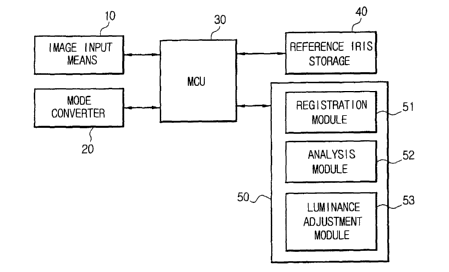
FIG. 2 shows an iris identification system according to a preferred
embodiment of the present invention.
As shown in FIG. 2, the iris identification system comprises an image
input means 10, a mode converter 20, a main control unit (MCU) 30, an iris
reference iris image storage 40, and an image control unit 50.
The image input means 10 comprises a camera for capturing an iris
image and an image-processing module (not shown).
The mode converter 20 comprises a keyboard (not shown) on which a
2o user selects one of sample-registering and -identification modes that are
respectively for registering an input iris image as a reference iris image and
for
identifying the input iris image by comparing with the previously registered
reference iris images.
6
CA 02425012 2003-04-04
WO 02/31750 PCT/KRO1/01499
The iris reference iris image storage 40 stores the registered iris
samples under control of the MCU 30.
The image control unit 50 comprises a sample-registering means 51 for
capturing a plurality of iris instances from the iris presented to the image
input
means 10 in various luminance environments and registering the iris instances
as reference iris images per person in the sample-registering mode, an image
analysis module 52 for comparing a presented image from the image input
means 10 with the reference iris images and analyzing similarities between the
presented image and the reference iris images so as to verify identification
in
Zo the identification mode, and a luminance adjustment module 53 for detecting
a
luminance of the input image and adjusting a brightness around the iris if
fihe
luminance is higher or lower than a predetermined luminance level.
The MCU 30 controls the image control unit 50 in order for the
registration module 51 of the image control unit 50 to classify iris instances
from
15 the image input means 10, to register the iris instances as the reference
iris,
and to store the registered reference iris images in the iris reference iris
image
storage 40 in the registration mode, and in order for the image analysis
module
52 of the image control unit 50 to compare the presented image from the image
input means 10 with the reference iris images and to analyze similarities
2o between the presented image and the reference iris images so as to verify
identification in the identification mode. Also, the MCU 30 controls the
luminance adjustment module 53 of the image control unit 50 in order for the
luminance adjustment module 53 detects luminance of the input image so as to
adjust the light amount radiating to the iris when the luminance is higher or
7
CA 02425012 2003-04-04
WO 02/31750 PCT/KRO1/01499
lower than a predetermined luminance level.
The MCU 30 can be structured so as to integrate the iris reference iris
image storage 40 and the image control unit 50.
The luminance adjustment module 53 adjusts intensity of visible ray
around an eyepiece (not shown) of the image input means 10 so as to be able
to adjust a pupil radium of an eye to be captured as iris instances or
presented
iris image. Also, the luminance adjustment module 53 can further adjust the
luminous intensity by radiating invisible ray when the adjusted intensity of
visible
ray is less than a predetermined intensity.
1o The registration module 51 takes several iris instances having
respective pupil radius from an individual iris, registers the iris instances
as the
reference iris images at corresponding classes that are classified according
to
the pupil radius and stores the registered reference iris image in the iris
reference iris image storage 40.
FIG. 3 is a drawing for illustrating a process of comparing an input iris
image to reference iris images stored in the iris reference iris image storage
40
and FIG. 4a and FIG. 4b are a set of drawings for illustrating how an iris
image
is classified.
Referring to FIG. 4a and FIG. 4b, the iris image is distinguished
2o according to a size of pupil dilating in the iris where r is pupil radium
and d is iris
radium (d>r). That is, the class is determined by the constant "r" which
increases to a maximum value in the iris radium "d". A whole class range (3
can
be expressed as follows.
s
CA 02425012 2003-04-04
WO 02/31750 PCT/KRO1/01499
x=~
n
where, n is number of class, and x is range of each class.
FIG. 5 is a diagrammatic view for illustrating the iris image vertically
partitioned and assigned with priorities and FIG. 6 is a diagrammatic view for
illustrating the iris sectored in each band of FIG. 5.
As shown in FIG. 5, the iris image is vertically partitioned up and down
on the basis of a horizontal axis x at a predetermined interval and each band
is
assigned with a priority corresponding to the band (for example, A1>A2A3, ...,
A10>A11 >A12) in the registration module 51. The priority is assigned from the
to band near the horizontal axis x to the band contacting to an exterior iris
boundary in the descendent order such that the band just below the horizontal
axis x has the highest priority. Also, the priority is assigned alternately in
such
an order of A1, A2, A4, A5, A7, A10 in downward direction and A3, A6, A8, A9,
A11, A12 in upward direction.
15 Referring to FIG. 6, the bands are horizontally divided by a
perpendicular line (y axis) passing the center of the pupil such that each
band
forms a pair of symmetrical blocks. Each block is defined by the vertical
width of
the band and exterior iris radium and pupil radium such that the block having
the highest priority is defined by the band width and the horizontal length
from
2o Xa to Xd. A maximum horizontal length of a block can be expressed as
following
inequality.
Xd I < Amax ~I < I~~ I (only, I Xa I > IXd I )
9
CA 02425012 2003-04-04
WO 02/31750 PCT/KRO1/01499
Thus, a maximum dimension maxi of the block can be calculated as
following equation.
maxi = (I~dI -IXQI)Y
wherein y is a vertical width of each band.
The registration module 51 determines a pupil boundary by calculating
an average luminance (Ima, !mb) by averaging luminance (la, Ib) of pixels of
the
iris image. The average luminance is calculated by following equation 1.
<Equation 1 >
When Im~n < Ib < In,a ,
1
I»,b = N ~Ib
b
where 1",p = N ~ la , IQ (I6 ) is luminance of a pixel, I",a (I",b ) is an
p
average luminance, Na(Nb) is number of executions, and Im;n is a minimum
luminance limit.
FIG. 7a to FIG. 7d are a set of drawings for illustrating how a center of
m the pupil of the iris image is obtained by the registration module.
Referring to FIG. 7, once an iris image is taken, two points of S(x~, y~)
and E(x2, y2) are randomly selected on the pupil boundary of the iris image so
as to create a segment SE by drawing a line connecting the points S and E.
Then, a imaginary perpendicular line is drawn from a center of the segment SE
2o such that the perpendicular line crosses the pupil boundary at a point
C(x3, y3).
A random center I;(xo, yo) of the pupil is calculated by the following
equation 2a.
<Equation 2a>
to
CA 02425012 2003-04-04
WO 02/31750 PCT/KRO1/01499
1
a = 2 (xy - xz)z + (Yi - Yz)z
1
c = ~ (x~ +xz -2x3)z +(Yi +Yz -2Y3)z
d 2c (az cz)
D=tan-'(Y'-Yz)_~'
x~ -xz 2
xo = d ~ cos D + ~ (x1 + xz )
Yo = -(d ~ sin D + 2 (Y1 + Yz ))
The registration module 51 calculates a plurality of candidate centers I;
of the pupil using the equation 2a and extracts the candidate centers (xo;,
Yon:) of
which radius are in the whole class range (3. These candidate centers are used
xo in order to obtain a final pupil center Tp(xp, yp). The final pupil center
Tp is
calculated as following equation 2b.
<Equation 2b>
xP = ~ ~xor ~ Yp = ~ ~Yoa
Also, on the basis of the final pupil center TP, a coordinates (xm, ym) of a
pupil boundary is calculated as following equation 2c.
Also, the registration module 51 determines iris boundary and iris
radium using the equation 2c.
FIG. 8a ~ FIG. 8d are drawings for illustrating for distribution of data in
iris image and how the data is compensated.
n
CA 02425012 2003-04-04
WO 02/31750 PCT/KRO1/01499
The iris image is stored into the storage medium 40 in the unit of block
after the every blocks are classified into a main, auxiliary, negative main
data
according to a pixel density of the blocks. In this case, the iris image data
is
stored as an absolute coordinates to the iris center.
As shown in FIG. 8a, areas of the iris image where the luminosities are
less than a standard luminance are set as the auxiliary data, and any portion
of
the auxiliary data having the same luminance and where the pixel density is
greater than a predetermined density value becomes main data (see FIG. 8b).
The negative main data are portions where the pixel densities are less than a
to predetermined value among the areas of which the luminosities are greater
than
the standard luminance in the iris image (see FIG.Bc).
The auxiliary data is divided into two portions on the basis of a
predetermined luminance level so as to set a portion near the lowest luminance
level as an upper luminance level portion and to set a portion near the
standard
15 luminance as a lower luminance level portion such that the auxiliary data
is
stored with information on one of the upper and lower luminance level
portions.
Also, a compensation area is formed up and down from the predetermined
division luminance level (see FIG. 8d) such that the data level of a dim iris
image can be compensated through the exclusive-OR and logical multiply
2o computation.
The auxiliary data is stored together with the corresponding absolute
coordinates, Boolean information on which level the data belong to, and
compensation information on a level dependency of the Boolean value.
For example, the compensation information is a Boolean data type such
12
CA 02425012 2003-04-04
WO 02/31750 PCT/KRO1/01499
that when an associated portion of the luminance level of the image crosses
the
two levels or contacts one of both, the value becomes 1.
That is, the auxiliary data is an area where an areal pixel density pm of a
negative cognitive factor of the iris image is greater than that of the
predetermined luminance standard point ~ (pm >~).
The upper and lower levels (L~ ) of the auxiliary data is 1 when p», ' 2 r~
and 0 when p", < 2 r1 .
The compensation level (L~) is 1 or 0 when the auxiliary data satisfies
the condition of 5 r~ <- p", <_ 5 r1 .
1o The main data is the area where the number of the pixels (Sp) of the iris
image is more than a number of standard pixels (PmaX).
That is, Sp=~{(x, -xo)Z +(y, -yo)2~?pm~X
where X,n~ >_ (x, - xo ), YmaX >_ (y, - yo ) , Pmax is standard pixel number,
Xmax is a limit of x axis length in pixel, YmaX is a limit of y axis length in
pixel, xo
15 and yo are center coordinates of a polar coordinates system, and x~ and y~
are
boundary coordinates of the polar coordinates system.
The process for registering a reference iris image by the registration
according to a preferred embodiment of the present means will be described ,
with reference to FIG. 9 and FIG. 10a, FIG. 10b, and FIG. 10c hereinafter.
2o Referring to FIG. 9, once the MCU 30 is set to the registration mode by
the mode converter 20 and an iris image is inputted through the image input
means 10, the registration module 51 of the image control unit 50 takes
several
I3
CA 02425012 2003-04-04
WO 02/31750 PCT/KRO1/01499
iris instances having different pupil radius and classifies the iris instances
into at
least one class according to the pupil radius at step S110 and determines
whether the number of the taken images (S) are greater than 0 at step S130. If
the number of the taken image is 0, the registration module 51 outputs the
result at step S310 and ends the registering algorithm. If the number of the
taken image is greater than 0 at step S130, a counter (N) increases from 1 to
8
at step S150. At the same time, the registration module 51 vertically
partitions
each image so as to form a plurality of bands at step S170. Next, the
registration module 51 determines whether or not the bands are successfully
1o formed at step S190. If the bands are successfully formed, a variable B1 is
set
to TRUE. If the variable B1 is set to TRUE, the registration module 51 divides
the bands so as to form symmetric blocks at step S210 and then store the iris
image data into the storage medium 40 in the unit of block at step S250. While
processing the iris image, the registration module 51 increases an image
storing
15 counter (I) and the image counter (N) one by one at step S270 and S290.
FIG. 10a is a flowchart for illustrating an image-taking routine of the
reference iris image-registering process.
As shown in FIG. 10a, in an state where the variables are initialized
once an iris image is inputted at step S112, while the luminance adjustment
2o module 53 adjusts the intensity of the visible ray around the iris (Q=N x
qi,
wherein qi is a maximum luminance limit constant) to be registered and
compensates the intensity of the visible ray at step S114 such that the pupil
radium of the eye is adjusted at step S113, the registration module 51
captures
effective images at step S115. Next, the registration module 51 analyzes the
14
CA 02425012 2003-04-04
WO 02/31750 PCT/KRO1/01499
captured image and determines whether or not the iris image is appropriate as
a reference iris image at step S117. If the iris image is not the appropriate
one,
the algorithm goes to step S115 and if the iris image is appropriate as the
reference iris image, the registration module 51 classifies the iris images
according to the pupil radius at step S118 and determines whether or not there
exist a same image that belongs to the same class in the storage medium 40 at
step S119. if the same image exists, the registration module determines that
the
image is suitable and increases the variables S and N by 1 at steps S120 and
S121. At step S119, if the same image does not exist, the registration module
51 increases just the variable N by 1.
FIG. 10b is a flowchart for illustrating a luminance compensation routine
at step S114 of FIG. 10a.
In the luminance compensation routine, the registration module 51
analyzes luminance Q of the presented image at step S114-1 and then
determines whether or not the presented image luminance Q is less than a
predetermined standard luminance M at step S114-2. If the presented image
luminance Q is less than the standard luminance, the luminance adjustment
module 53 irradiate infrared ray so as to adjust the image luminance at step
S 114-3.
2o FIG. 10c is a flowchart for illustrating an iris image-partitioning routine
at
step S170 of fihe reference iris image-registering process of FIG. 9.
In the iris image-partitioning routine, the registration module 51 defines
the pupil boundary using the Equafiion 1 at step S171 and the center of the
pupil
through the Equations 2a ~ 2b at step S172. Next, the registration module 51
is
CA 02425012 2003-04-04
WO 02/31750 PCT/KRO1/01499
defines the size of the iris on the basis of the pupil center and the pupil
boundary at step S173. After the iris size is defined, the registration module
51
vertically partitions the iris image so as to form a plurality of bands at
step S174.
FIG. 11 is a flowchart for illustrating an identification process of the iris
identification method of the present invention.
Referring to FIG. 11, once the MCU 30 is set to the identification mode
by the mode converter 20 and at least one iris image is inputted at step S410,
the image analysis module 52 of the image control unit 50 determines whether
or not the iris image is proper for comparison with the reference iris images
at
1o step S420. If the iris image is not proper, the identification algorithm
returns to
the step S410. If the iris image is proper at step S420, the image analysis
module 52 retrieves corresponding reference iris class from the storage medium
40 at step S430 and determines whether or not the corresponding iris class
exists in the storage medium 40 at step S440. If the corresponding iris class
15 does not exist, the image analysis module outputs a denial message at step
S530 and ends the identification session.
At step S440, if the corresponding iris class exists in the storage
medium, the image analysis module 52 starts comparing the presented iris
image with the reference iris images belonged to the corresponding iris class
at
2o step S450. While the data comparison, the image analysis module 52 creates
vertical bands and sets data blocks so as to compare the presented iris image
and the reference iris image in the unit of block at step S470. That is, the
main,
auxiliary, and negative main data of corresponding blocks of the presented
iris
image and the reference iris image are respectively compared. In this case,
the
16
CA 02425012 2003-04-04
WO 02/31750 PCT/KRO1/01499
comparison is performed at corresponding absolute coordinates in descendent
order of the priority.
At step S470, if the band is inappropriate, the image analysis module 52
determines whether the luminance Q is equal to or greater than a
predetermined value at step S510. If the condition is satisfied at step S510,
the
image analysis module 52 displays the approval result at step S520.
On the other hand, if the band is appropriate at step S470, the image
analysis module 52 analyzes the equalities of main, auxiliary, and negative
main data of the of each block (q1 = Q) at step S480 and band dependency (qx)
1o at step S490. In this case, the band dependency is weighted in accordance
with
the band priority of the data block. Consequently, if the presented iris image
satisfies the condition of Q>Min at step S510, the image analysis module 52
outputs the identification result at step S520. On the other hand, if the
presented image does not satisfy the condition, the image analysis module 52
r5 outputs the denial result at step S530. The final result is expressed by
the
equality, that is an absolute element, together with adoption extent of the
compensation level of the auxiliary data.
As described above, in the iris identification system and method
according to the preferred embodiment of the present invention, an input iris
2o image is stored in the several states as reference iris images that have
different
pupil sizes in order for each reference iris image to belong to a class in the
registration mode, once an iris image is input for being verified, the input
iris
image is compared with a reference iris image belong to the corresponding
class in the identification mode, and the input iris image is firstly regarded
as
17
CA 02425012 2003-04-04
WO 02/31750 PCT/KRO1/01499
just a candidate image even though corresponding reference iris images exist
in
the system and excludes further analysis especially when the pupil radium of
the input image is different from that of the reference iris classes so as to
considerably reduce the possibility of misidentification.
The misidentification rate (e) can be expressed as followings.
acsp
a=(2 R )
wherein, S~, is number of pixels of the iris, A is a percentage of the iris
characteristic factor to the iris, B is a number of averaged pixel, and C is a
percentage value of the band priority rate to the iris exposure.
~o While this invention has been described in connection with what is
presently considered to be the most practical and preferred embodiment, it is
to
be understood that the invention is not limited to the disclosed embodiments,
but, on the contrary, is intended to cover various modifications and
equivalent
arrangements included within the spirit and scope of the appended claims.
i8