Note: Descriptions are shown in the official language in which they were submitted.
CA 02425020 2008-11-14
25561-220
- 1 -
Device for processing flat objects, especially printed
products
The present invention relates to a device for processing
flat objects, especially printed products.
A device of this type has been disclosed in EP-A-0 771 754
and the corresponding US-A-5,765,823. A saddle-like rest
as well as a rest wall and carrier elements having a base
are arranged at a distance one behind the other in the
manner of a cantilever on an endless flexible drive element
which is driven continuously. The flexible drive element
is configured as a conveyor chain guided in a channel over
rolls. A first feed station is intended either for
depositing folded printed products opened and in straddling
form onto the saddle-like rest of the carrier elements
moving past it or for feeding printed products to the
carrier elements in such a way that they come into contact
with the base and rest wall. Processing stations
configured as further feed stations are arranged downstream
of the first feed station as seen in the conveying
direction of the flexible drive element forming the
conveying mechanism, with the same intended purpose as the
first feed station. At an output station downstream of the
processing stations, the combined printing products are
removed from the carrier elements and output for further
processing.
In the case of this known device all the stations must
operate synchronously with the continuously driven endless
flexible drive element.
It is therefore an object of an embodiment of the present invention
to develop the known device such that it can be adapted or is
CA 02425020 2008-11-14
25561-220
- 2 -
adapted more flexibly to the boundary conditions required by
the individual stations.
According to an aspect of the invention, there is
provided a device for processing flat objects, especially
printed products, having a rail system, carrier elements
arranged on a conveying mechanism which is driven in the
conveying direction and guided by the rail system, and said
carrier elements having a saddle-like rest and/or a rest
wall and a base, a feed station which is intended for
feeding objects to the carrier elements moving past it, a
processing station arranged downstream of the feed station
as seen in the conveying direction, and an output station
arranged downstream of the processing station as seen in the
conveying direction and intended for removing the objects,
wherein a plurality of individually movable, rail-guided
conveyor elements are present, each of the carrier elements
is arranged on a single one of the individual conveyor
elements, the processing station is configured as a further
feed station or has a processing assembly for processing the
objects fed by means of the carrier elements, and each of
the stations has a dedicated drive arrangement for the
conveyor elements which is intended for transporting the
conveyor and carrier elements at a spacing and a speed
required by a assigned station.
The conveying mechanism is formed by a large
number of conveyor elements which can be moved individually
in a rail system, each of the carrier elements preferably
being arranged on one of the conveyor elements in the*manner
of a cantilever. The conveyor elements and thus carrier
CA 02425020 2008-11-14
25561-220
- 2a -
elements are decoupled from each other and can be moved
individually in the rail system. If the conveyor elements
rest on each other they can of course be moved forward by
the transmission of impact forces, but they do not exert
any tensile forces on each other. Each of the stations -
the feed station, the processing station or stations and
the output station - has a dedicated drive arrangement for
the conveyor elements, which convey the conveyor and
carrier elements at the spacing and speed required by the
station in question. Each station can be operated
optimally by virtue of the conveyor elements being
decoupled and by virtue of the dedicated drive
arrangements, the stations being independent of one
another.
Sections of the rail system serving as a buffer-storage
section allow buffer storage of carrier elements and of the
objects transported by means of the latter. In this way it
is also possible to considerably compensate for stations
being interrupted.
Particularly preferred embodiments of the invention permit a
modular construction of the device.
CA 02425020 2003-04-07
WO 02/36474 PCT/CH01/00643
- 3 -
Further particularly preferred embodiments of the device
according to the invention are specified in the further
dependent patent claims.
The invention will be explained in more detail using
exemplary embodiments depicted in the drawing. In the
drawing, purely schematically:
Fig. 1 shows a plan view of a device embodied as a
circulating system;
Fig. 2 shows a detail of the device according to fig. 1
with individual conveyor elements and carrier
elements arranged in the manner of a cantilever
on the latter;
Fig. 3 shows a further possible embodiment of a section
of the device with a station and a three-
dimensionally curved section of the rail system;
Fig. 4 shows a station together with a section of the
rail system assigned to it and the drive
arrangement assigned to it with further upstream
and downstream sections of the rail system;
Fig. 5 shows a section of the rail system with a
supporting means, acting, for example, as an
auxiliary drive, for the carrier elements;
Fig. 6 shows a section of the rail system with a
queuing element connected and a station arranged
in the queuing section;
Fig. 7 shows two feed stations arranged one behind the
other with associated drive arrangements which
CA 02425020 2003-04-07
WO 02/36474 PCT/CHO1/00643
- 4 -
move the carrier elements at a specific spacing
through the stations;
Fig. 8 shows a section of a device according to the
invention with a rectilinear section of the rail
system and a stapling apparatus, and
Fig. 9 shows part of a device according to the
invention with a stapling apparatus arranged in
a curved section of the rail system.
The device shown in fig. 1 has a rail system 10 which
extends in a horizontal plane and is intrinsically closed.
Two semicircular rail sections 12 are connected to each
other by means of rectilinear rail sections 14 to form a
circulating system. A large number of individual conveyor
elements 16 are arranged one behind the other in the rail
system 10 and are guided so that they can move freely along
the rail system. The number of conveyor elements 16 is
selected such that they do not form an intrinsically closed
impact chain by resting on each other; in other words there
are gaps between individual successive conveyor elements.
A carrier element 18 is fastened to each of the conveyor
elements in the manner of a cantilever, said carrier
element projecting outward from the conveyor element 16 in
the radial direction with regard to the rail system 10.
A first feed station 20 is indicated by a dash-dotted
rectangle. It is assigned a dedicated drive arrangement 22
which is intended for moving conveyor elements 16 and hence
the carrier elements 18 at a specific spacing A and at a
specific speed v through the feed station 20 in the
conveying direction F so that said feed station can feed a
flat object, for example a printed product, to each carrier
CA 02425020 2003-04-07
WO 02/36474 PCT/CH01/00643
- 5 -
element 18.
A processing station 24 likewise with a dedicated drive
arrangement is arranged at a distance from and downstream
of the feed station 20 as seen in the conveying direction
F. This processing station is intended for moving the
conveyor elements 16 in the buffer-stored state, i.e.
resting on each other, and thus the relevant carrier
elements 18 through the processing station 24 at a minimum
spacing B and a speed specified by said processing station.
In the processing station, a further object can be
attached, for example adhesively bonded, to the objects fed
in the feed station 20, or any other desired processing
operation on the relevant objects can take place.
A further processing station which is configured as a
further feed station 26 is arranged downstream of and at a
distance from the processing station 24. Its construction
and functioning correspond to those of the feed station 20.
A drive arrangement 22' is assigned to a further section of
the rail system, the object of which drive arrangement is
to drive the incoming conveyor elements 16 in the conveying
direction F so that they reach an output station 28. Said
output station in turn has a dedicated drive arrangement
which is intended for moving the conveyor elements 16
through the output station 28 in the buffer-stored state -
spacing B. The objects fed to the carrier elements 18
upstream and processed in the processing station 24 are
removed from the carrier elements 18 in the output station
28 and fed to a further processing operation.
A drive arrangement 22' is assigned to a further rail
section downstream of the output station 28 in order to
feed the carrier elements 18 to the feed station 20 again.
CA 02425020 2003-04-07
WO 02/36474 PCT/CH01/00643
- 6 -
The device can be adapted to the individual requirements as
all the stations 44 mentioned and the rail system 10 are of
modular construction. It is thus conceivable, for example,
to arrange stations 44 in turn between the output station
28 and the feed station 20, as seen in the conveying
direction F, it being possible for said stations to form a
dedicated processing path for objects or said stations
forming a single processing path together with the stations
44 shown further above.
Fig. 2 shows a section of the device represented in fig. 1
with three conveyor elements 16 resting on the end of each
other in the buffer-stored state. Each of the conveyor
elements 16 has a conveyor-element body 30 on which a
horizontal carrier shaft 32 is fastened in the manner of a
cantilever. Said carrier shaft carries a carrier element
18 formed, for example, from metal sheet at a distance from
the conveyor-element body 30, said carrier element firstly
forming a saddle-like rest 34 and secondly having a flat
rest element 36 and an adjoining base 38. A multipart flat
object 40, for example a first printed product, lies on the
base 38 and on the rest wall 36, said object having been
fed to the carrier element 18 by means of the feed station
20 (fig. 1), for example. A further folded object 40' sits
in straddling form on the rest 34 and covers the object 40.
The object 40' has been opened for example by means of the
further feed station 26 (fig. 1), and deposited onto the
rest 34.
Guide wheels 42 are mounted such that they can rotate
freely on each conveyor-element body 30 and mount the
conveyor element 16, in the manner of a carriage and such
that it can move freely, on the rail which is C-shaped in
cross section. The ends of the conveyor-element bodies 30
are configured as abutting surfaces in order to rest on the
CA 02425020 2003-04-07
WO 02/36474 PCT/CH01/00643
- 7 -
facing end of the conveyor-element body 30 of the adjacent
conveyor element 16 in the buffer-stored state.
Fig. 3 schematically shows a processing station 24 with an
associated rail section 12'. The drive arrangement
assigned to this processing station 24 is not shown. It is
intended for moving the conveyor elements 16 - these and
the carrier elements 18 are configured identically to those
shown in fig. 2 and described further above - at a
predetermined spacing and at a predetermined speed through
the processing station 24. This movement can of course be
carried out continuously or in start/stop operation.
A further rail section 12" serving as a connecting path is
connected downstream of the rail section 12' and is three-
dimensionally bent with narrow radii. It is also an object
of the processing station 24 to release the conveyor
elements 16 with such a spacing that they can move through
the pronounced curvature of the rail section 12" without
hindering each other. This rail section 12" may, for
example, be sloped so that no further drive arrangement is
necessary.
A further possibility for arranging the rail guidance means
with regard to the conveyor and carrier elements 16, 18 is
indicated by dash-dotted lines. The conveyor elements 16
are correspondingly located adjacent to the base 38, for
example approximately centrally as seen in its longitudinal
direction.
Fig. 4 shows a station 44, configured as a module or
modular insert, which may be a feed station 20, a
processing station 24 or an output station 28 and has a
permanently assigned rail section 12' and a dedicated drive
arrangement 22. Rail sections of adjacent stations adjoin
CA 02425020 2003-04-07
WO 02/36474 PCT/CH01/00643
- 8 -
both ends of the rail section 12', the two adjacent
stations in the example shown being configured as buffer-
storage stations 46 each having a dedicated rail section
12"' and a dedicated drive arrangement 22.
The drive arrangement 22 of the station 44 has a belt 48
which is driven in circulation and moves the conveyor
elements 16 through the station 44 with a form-fitting or
force-transmitting connection at a predetermined mutual
spacing and at a stipulated speed. A feeder wheel or a
controlled release device, for example, may be provided on
the entry side of the drive arrangement 22 in order to feed
or release in each case a conveyor element 16 to the belt
48 at the desired times for driving.
The buffer-storage stations 46 have a further belt 48'
which is driven in circulation in the conveying direction F
and drives the conveyor elements 16 in the conveying
direction F, for example by means of a frictional or
magnetic connection, until said conveyor elements rest on
one another in the buffer-stored state.
In the embodiment shown in fig. 5, the carrier shafts 32 of
the carrier elements 18, on the side facing away from the
conveyor elements 16, project beyond the rest 34 and the
rest element 36. The rail section 12' shown is likewise
assigned a drive arrangement 22 which drive the conveyor
elements 16 in the conveying direction F in a manner which
permits slip to occur. The station 44 shown in fig. 5 has
an auxiliary drive arrangement 50 which also serves as a
supporting device and has a pulling element 52 which is
driven in the conveying direction F, is intrinsically
closed and has groovelike recesses 52' at predetermined
spacings for accommodating the free end regions of the
carrier shafts 32. The spacing and the conveying speed of
CA 02425020 2003-04-07
WO 02/36474 PCT/CHO1/00643
- 9 -
the carrier elements 18 is stipulated in this case by the
auxiliary drive arrangement 50. Upstream of the station
44, a rail section 12"' serving as a buffer-storage path is
provided, for example with a slope, from which rail section
in each case one conveyor element 16 is sequentially taken
by means of the auxiliary drive arrangement 50 and moved
through the station 44 at the desired spacing from the
preceding carrier element 18. The carrier elements 16 are
supported at both ends in the station 44 shown in fig. 5.
This can be advantageous in particular when processing
operations are to be performed on the objects 40, 40', for
example if objects deposited on top of one another are to
be connected to one another by means of staples.
Figure 6 shows part of a station 44 which has a queuing
element 54 connected at its downstream end. Adjoining the
queuing element 54 in the upstream direction, the station
44 has a dedicated drive arrangement 22 with a belt 48
which is driven in circulation in the conveying direction
F. Said belt is intended for driving conveyor elements 16
which come into its active region until they come into
contact with the respective preceding conveyor element 16.
The force-transmitting coupling between the belt 48 and the
conveyor elements 16 can be formed, for example, by a
frictional connection or magnetic connection. In this case
the station 44 requires the carrier elements 18 to be
stationary for it to process objects 40, 40' which are
either to be fed to the conveyor elements 16 or have
already been fed to them earlier by means of a feed station
20. At the cycle rate stipulated by the station 44, the
queuing element 54 releases in each case one conveyor
element 16, which is fed to the next rail section 12 in the
conveying direction F by means of the drive arrangement 22.
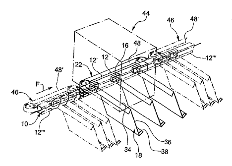
Figure 7 shows a feed station 20 and a processing station
CA 02425020 2003-04-07
WO 02/36474 PCT/CHO1/00643
- 10 -
24 arranged at a distance and configured as a further feed
station 26, these two stations each having an associated
rail section 12' and an associated drive arrangement 22.
Each of the two drive arrangements 22 has a belt 48 which
is driven in circulation in the conveying direction F at a
specific conveying speed and from which catching cams 56
project at a spacing one behind the other. These cams are
intended for achieving form-fitting engagement with the
conveyor elements 16 in order to move them through the feed
stations 20, 26 at the desired spacing and at the required
conveying speed.
The feed station 20 is intended for feeding an object 40
from above to each of the carrier elements 18. In the
example shown, the object is a folded printed product in
which a further part product is arranged. The printed
products are fed with the fold at the front so that their
fold comes into contact with the base 38 and they can be
transported further with their flat side lying on the rest
element 36. The further feed station 26 is intended for
opening, in a known manner, objects 40' configured as
folded printed products and depositing them in straddling
form onto the saddle-like rests 34 of the carrier elements
18 in such a way that they cover the objects 40 fed in the
feed station 20.
Fig. 8 shows a rectilinear rail section 12' which is
assigned to a processing station 24 having a stapling
apparatus 58. The drive arrangement 22 of this processing
station 24 is intended for moving the conveyor elements 16
resting on one another through the processing station 24 at
the cycle rate of the stapling apparatus 58. The stapling
apparatus 58 has stapling heads 62 arranged at equal
spacings along the circumference of a carrying disk 60
driven in rotation. The spacing between the stapling heads
CA 02425020 2003-04-07
WO 02/36474 PCT/CHO1/00643
- 11 -
62 and the rotational speed of the carrying disk 60 are
matched to the spacing B between successive carrier
elements 18 in such a way that a stapling head 62 coincides
with each carrier element 18 with the result that said
stapling head can insert a staple into the objects 40'
deposited in straddling fashion onto the rests 34. Each
carrier element 18 is assigned a bending-over device 64
which is controlled, for example, by means of a slotted
guide 66 in such a way that the staples inserted into the
objects 40' are bent over in a known manner.
The mutual spacing of the carrier elements 18 is minimal in
the station 44 with the stapling apparatus 58 and thus
substantially smaller than in the feed stations 20, 26
shown in fig. 7. With the same processing capacity, the
conveying speed is thus slower in the case of the
processing station 24 shown in fig. 8 than in the feed
stations 20, 26.
Fig. 9 likewise shows a processing station 24 with a
stapling apparatus 58 of the same construction as shown in
fig. 8 and described further above. The associated rail
section 12', however, is convexly curved with respect to
the stapling apparatus 58. This has the advantage that the
change in angle between the stapling head 62 and the
carrier element 18 takes place more slowly than in the case
of the embodiment according to fig. 8 with a rectilinear
rail section. The drive arrangement 22 in turn has a belt
48 which is driven in the conveying direction F and has
catching cams 56 for driving the conveyor elements 16 with
a form-fitting connection. As said conveyor elements are
moved through a curve, they are preferably held by means of
the drive arrangement 22 at a spacing from one another
which can be very small. A bending-over device 64 with
bending-over means is also attached in this case to the
CA 02425020 2003-04-07
w0 02/36474 PcT/cx01/00643
- 12 -
rest element 36 of each carrier element 18, said bending-
over means being moved by means of a slotted-guide control
means so as to bend over staples.
The modules can be combined as desired to form a device
because the stations 44 and the rail system 10 are
constructed in modular fashion.
The carrier elements 18 can naturally also be of pocket-
shaped configuration and/or have opening and holding-open
elements or closing elements for the objects 40.
For the sake of completeness, it should be mentioned that
the device always has a feed station 20 and an output
station 28 and, between them, at least one processing
station 24, it being possible for the latter also to be
configured as a feed station 26. The processing station
can, however, fulfill any other desired function.
In the embodiments shown, the rail system 10 has an
intrinsically closed rail which comprises rail sections 12,
12', 12", 12"' arranged one behind the other. A more
complex rail system with diverters and the like is,
however, also feasible, the diverters in turn preferably
being configured in the manner of a processing station 24.
The carrier elements 18 do not necessarily have to have
saddle-like rests 34 if objects 40' are not to be deposited
in straddling fashion onto said rests. They can, however,
also only have such rests 34 but no rest elements 36 or
bases 38 if the objects 40' are only to be deposited in
straddling fashion onto the rests 34 for processing.
In particular it is possible to keep the spacing of
successive carrier elements small when collating objects
CA 02425020 2003-04-07
WO 02/36474 PCT/CHO1/00643
- 13 -
and to select a larger spacing when collecting because
spread products are to be deposited in straddling fashion
onto the rests during collecting.
The device according to the invention is also suitable in
particular for addressing objects, for gluing in cards, for
example, or for inside printing, as the spacing between
successive carrier elements can be selected in the stations
44 according to the requirements.
The device according to the invention allows the most
diverse functions and processing operations to be performed
on the same conveying path (i.e. rail system) without
impairing smooth processing. The correspondingly required
spacings can be set in the entire process sequence even in
the case of mixed feeds - for example as shown in fig. 7 -
and/or mixed processing.