Note: Descriptions are shown in the official language in which they were submitted.
CA 02425059 2003-04-04
WO 02/28329 PCT/USO1/31109
NEUROSURGICAL DEVICE FOR THERMAL THERAPY
INCLUDING SPIRAL ELEMENT
CROSS-REFERENCE TO RELATED APPLICATION
This application is related to and claims priority to U.S. Provisional Patent
Application
Serial No. 60/238,314, filed 10/05/00, entitled Systems and Methods for
Controlling
Temperature of Brain Tissue, the entirety of which is incorporated herein by
reference.
STATEMENT REGARDING FEDERALLY SPONSORED RESEARCH OR DEVELOPMENT
n/a
FIELD OF THE INVENTION
1o The present invention relates to systems and methods for controlling brain
tissue
temperature, and in particular to systems and methods for subcranial
temperature control of brain
tissue through the use of contact cooling devices.
BACKGROUND OF THE INVENTION
is Researchers and physicians have long recognized the consequences of
reduction of body
temperature in mammals, including induction of stupor, tissue damage, and
death. Application of
freezing and near freezing temperatures to selected tissue is commonly
employed to preserve
tissue and cell (e.g. sperm banks); and application of extreme cold (far below
freezing) is
effective for tissue ablation. However, localized cooling (not freezing) of
tissue has generally
2o been limited to the placement of an "ice-pack" or a "cold compress" on
injured or inflamed
tissue to reduce swelling and the pain associated therewith. Localized cooling
of internal organs,
such as the brain, has remained in large part unexplored.
For example, "brain cooling" has been induced by cooling the blood supply to
the brain
for certain therapies. However, as the effects of the cool blood cannot be
easily localized, there is
25 a systemic temperature reduction throughout the body that can lead to
cardiac arrhythmia,
immune suppression and coagulopathies.
Attempts have been made to localize cooling of the brain with wholly external
devices,
such as cooling helmets or neck collars. However, there are disadvantages
associated with
external cooling to affect internal tissue. For example, external methods do
not provide adequate
CA 02425059 2003-04-04
WO 02/28329 PCT/USO1/31109
resolution for selective tissue cooling, and some of the same disadvantages
that are associated
with systemic cooling can occur when using external cooling devices.
It is therefore desirable to obtain improved devices and methods that allow
for localized
brain cooling without the disadvantages of the known systemic and external
devices and
techniques.
SUMMARY OF THE INVENTION
The present invention overcomes the disadvantages of known systemic and
external
devices and techniques by providing localized brain cooling with a device
placed through the
1o skull.
The present invention provides a device and method for localized temperature
control of a
body part, such as the brain. In an exemplary embodiment, a device for
thermally affecting tissue
of a patient includes a housing defining an interior volume that is at least
partially insertable into
an exterior opening in a patient, such as a burr hole though the skull. A
thermal member
15 positioned within the interior volume of the housing includes a thermal
input side and a thermal
output side to impart a thermal change to the tissue. An exemplary method of
treatment using the
device includes the steps of exposing tissue to be thermally affected;
attaching a thermal device
to an anchor point of the body; positioning the thermal member near or on the
tissue; and
operating the thermal member to thermally change the temperature of the
tissue.
BRIEF DESCRIPTION OF TIDE DRAWINGS
A more complete understanding of the present invention, and the attendant
advantages
and features thereof, will be more readily understood by reference to the
following detailed
description when considered in conjunction with the accompanying drawings
wherein:
FIG. 1 is a perspective view of an exemplary embodiment of a device
constructed in
accordance with the principles of the present invention;
FIG. 2 is a section view taken along section 2 - 2 of FIG. 1;
FIG. 3 is a side view of a base of the device;
FIG. 4 illustrates a contact member on the bottom of the device of FIG. 1;
3o FIG. 5 is an exploded view of another embodiment of a device constructed in
accordance
with the principles of the invention;
2
CA 02425059 2003-04-04
WO 02/28329 PCT/USO1/31109
FIG. 6 is a perspective view of yet another device constructed in accordance
with the
principles of the invention;
FIG. 7 is a section view taken along section 7 - 7 of the devise shown in FIG.
8;
FIG. 8 is a sectional side view of an expansion element of the device of FIG.
9;
FIG. 9 is a sectional end view of an expansion element of the device shown in
FIG. 7;
FIG. 10 is a sectional view of an alternative arrangement of a device
constructed in
accordance with the principles of the present invention;
FIG. 11 illustrates in cross-section yet another arrangement of a device
constructed in
accordance with the principles of the present invention;
to FIG. 12 depicts the exemplary device of FIG.1 inserted through a skull;
FIG. 13 depicts the exemplary device of FIG. 8 inserted through a skull;
FIG. 14 is a perspective view of an exemplary surface area expansion element;
and
FIG. 15 is a perspective view of another exemplary surface area expansion
element.
DETAILED DESCRIPTION OF THE INVENTION
The present invention provides a device for applying thermal energy to a
localized region
of a body tissue. Referring now to the drawing figures in which like reference
designators refer
to like elements, there is shown FIG. 1 a perspective view of an exemplary
embodiment of a
device constructed in accordance with the principles of the present invention
and designated
2o generally as device 10. The device 10 includes a housing 12 with a first
end 14, a second end 16
and an optional circulation vent 18 through which a thermally conductive fluid
can pass. The
housing 12 can be constructed of any suitable material, for example metals,
plastics or a
combination thereof. It is contemplated that the housing 12 has a diameter
"D", measured at the
widest portion of the device, from approximately one centimeter to
approximately ten
centimeters. In an exemplary embodiments the diameter ranges from
approximately 1
centimeters to 1.5 centimeters. Optional radial threads 20 are provided on the
exterior of the
housing 12 to facilitate attachment to bone structure such as a skull.
However, it is contemplated
that non-threaded arrangements can also be provided or coupled to or on the
housing 12, for
example, flutes, barbs, ridges or other anchoring elements. The term fluid as
used herein refers to
3o a substance in a liquid state, a gaseous state, a transition state between
liquid and gas, or a
combination of any of the preceding.
CA 02425059 2003-04-04
WO 02/28329 PCT/USO1/31109
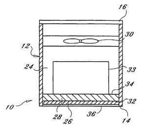
FIG. 2 is a sectional view of the device of FIG. 1, taken along line 2 - 2.
The housing 12
is a generally cylindrical body having a wall that defines an interior space
24. Provided within
the interior space 24, starting at the first end 14 and moving to the second
end 16, is a contact
member 26 which can be configured to directly contact a tissue or to contact
an intermediate
material. The contact member 26 can be constructed of any thermally conductive
material, for
example, stainless steel, aluminum, copper, titanium, various polymers or
other such materials.
Additionally, adjacent the contact member 26 is a thermal member 28. The
thermal member 28
has a thermal input side 32 in thermal communication with the contact member
26 and a thermal
output side 34. The thermal member 28 can be a thermo-electric cooler as is
known in the art, for
1o example, a pettier cooler. Optionally, a thermal dissipation member 33 is
provided in thermal
communication with the output side 32 of the thermal member 28. Such devices
are known in
the art, for example a common thermal dissipation member is a heat sink.
However, many
alternate components for dissipating thermal energy can be provided. Further,
it is contemplated
that fewer elements can be provided, for example the thermal member 28 can be
configured to act
as a thermal contact member without the aid of a separate element.
Further provided within the housing 12 in the interior space 24 is a fluid
circulation
member 30. The term "fluid" as used herein generally refers to any flowable
substance,
including but not limited to gasses and liquids. An exemplary fluid
circulation member 30 is a
cooling fan. The fluid circulation member 30 is positioned such that it
circulates a fluid, such as
2o air, across the thermal output side 32 of the thermal member 28 or the
optional thermal
dissipation member 33 if provided, thereby removing thermal energy dissipated
by the thermal
member 28. Alternatively, it is contemplated that a pump, used in association
with a thermally
conductive liquid, be provided to dissipate thermal energy generated by the
output side 32 of the
thermal member 28. In addition, an optional membrane 36 is provided in thermal
communication with the contact member 26. Membrane 36 can be constructed of
any bio-
compatible material and can be constructed to directly contact a tissue.
Referring to FIG. 2, the operation of an exemplary device is now discussed in
detail.
Power is supplied to the thermal member 28 through electrical wires (not
shown) which in turn
creates a thermal input side 32 and a thermal output side 34 to the thermal
member 28 (the
3o thermal member discussed here is a pettier cooler and its function is well
known in the art). fly
operation of the thermal member 28, the thermal input side 32 has a reduced
temperature relative
to the thermal output side 34 which causes a cooling effect at the thermal
input side 32. The
4
CA 02425059 2003-04-04
WO 02/28329 PCT/USO1/31109
thermal input side 32 being in thermally conductive contact with the contact
member 26, thereby
causes a reduction of the relative temperature of the contact member 26. The
output side 34
being in thermally conductive contact with the optional thermal dissipation
member 33 thereby
raises the relative temperature of the thermal dissipation member 33 (creating
heat).
Additionally, a current or activation energy is supplied to the fluid
distribution member 30 to
thereby circulate air through the thermal dissipation member 33 and out of
housing 12 through
the circulation vent 18. Heat dissipated by the thermal dissipation member 33
is removed and
discharged from the housing 12 to maintain a reduced temperature at the
contact member 26. As
such, the concepts of the present invention provide a device 10 for localized
cooling of a tissue in
to a compact configuration.
FIG. 3 is a side view of the contact member 26 showing a contact side 27
having a
concave surface as illustrated in phantom. The extent of curvature can
modified to accommodate
the requirements of the therapy and the tissue site to be treated. The depth
of the cavity formed
by the concave surface can be measured from the contact side 27 peapendicular
to the center 29
of the concave region. In exemplary embodiments the concave distance ranges
from
approximately 0.001 inches to approximately 0.05 inches. In the embodiment
shown in FIG. 3,
which is used to treat dura matter, the concave distance is approximately 0.02
inches.
FIG. 4 illustrates the first end 14 of the device 10, wherein a square-shaped
contact
member 26 is disposed within the housing 12. Optionally, one or more access
ports 38 are
2o provided through the housing 12 to allow passage or placement of devices
such as specialty
neuro-catheters, thermocouple probes, temperature sensors, and pressure
sensors. Alternatively,
an insert 40 can be provided to be completely or partially obstruct the access
port 38. The insert
40 can be constructed from any suitable material, for example, rubber,
silicone, aluminum or
other such materials. While FIG. 4 shows a square-shaped contact member 26, it
is contemplated
that various other shapes can be provided. Additionally, an access port (not
shown) can be
provided through the contact member 26 itself to accommodate accessory devices
as discussed
above.
FIG. 5 is an exploded view of another configuration for the device, wherein a
housing 48
has a wall 50 that defines an inner volume 52 to receive a thermal cartridge
58. The housing
3o includes longitudinal grooves 54 on the inner surface 53 of the wall 50.
Radial threads 56 can be
provided for securing the housing 48 to the skull. The thermal cartridge 58
has axial slots 60
configured to be slidably engagable with axial grooves 54 of the housing 48.
5
CA 02425059 2003-04-04
WO 02/28329 PCT/USO1/31109
The thermal cartridge 58 includes the exemplary elements as discussed above
for
applying thermal energy to a tissue site, for example, a contact member, a
thermal member, and a
cooling fan (not shown). In practice, the housing 48 is secured within a skull
opening by
screwing the radial threads into the bone. The thermal cartridge 58 is then
inserted into the inner
volume 50 of the housing 48 while aligning the axial slots 60 with the axial
grooves 52. The
thermal cartridge 58 can be slidably adjusted within the insert housing 48 in
order to specifically
locate the contact member against the dare matter.
Additionally, the thermal cartridge 58 can be moved in response to dare
swelling or
shrinkage that may occur during treatment. ~nce a desired distance of
insertion is reached, the
1o thermal cartridge 58 is held in position by a set screw 63 through a screw
opening 65 in the insert
housing 48. While FIG. 7 illustrates an axial groove and slot arrangement, it
is contemplated that
alternate configurations can be provided. For example, a spiral groove and
slot arrangement can
be provided which would provide insertion depth adjustment via rotation of the
thermal cartridge
relative to the housing.
15 FIG. 6 is a perspective view of another feature of the invention, wherein a
surface area
expansion element 62 is disposed at the first end 14 of the housing 12. The
surface area
expansion element 62 provides a tissue contact area that is larger than the
contact member 26 (not
shown). The surface area expansion element 62 has a height "H" measured from a
top 64 to a
tissue contact area 66 of the surface area expansion element 62 and a deployed
diameter "dd"
2o measured from the widest points at a periphery of the surface area
expansion element 62. In an
exemplary embodiment, the surface area expansion element 62 has a height to
width ratio of
approximately one to two. Further, a surface area expansion element 62
constructed in
accordance the principles of the present invention can have a deployed
diameter dd ranging in
size from 5 to 200 mm. An exemplary embodiment has a deployed diameter 34 of
48 mm.
25 Another exemplary embodiment has a deployed diameter 34 of 64 mm. Further,
an exemplary
embodiment can have a height H ranging in size from 1 to 10 mm. In one
exemplary
embodiment the height H is approximately 4 mm.
The surface area expansion element 48 can be provided by several different
structures,
such as an inflatable plenum such as a bladder or balloon. Alternatively, the
expansion element
30 48 can include foldable, rollable, or compressible, ribbons or resilient
thermally-conductive
structures. Exemplary resilient materials include rubber, silicon, flexible
polymers and other
materials known in the art. Thus, the surface area expansion element 62 is
provided with. a
6
CA 02425059 2003-04-04
WO 02/28329 PCT/USO1/31109
structure that allows it to be inserted through a small opening in a body and
then deployed to
increase the tissue contact area 66. The tissue contact area 66 can have,a
shape ranging from
substantially flat to concave.
FIG. 7 is a view taken along section 7 - 7 of the device shown in FIG. 6 to
show the
s hollow interior of the surface area expansion element 62. As illustrated,
the surface area
expansion element 62 has a wall 68 which defines an interior volume 70 which
is filled with a
thermally transmissive fluid 72. The contact member 26 is in thermal contact
with the interior
volume 70 'via the thermally transmissive fluid 72 at an interface 74. The
contact member 26 is
in~turn in thermal contact with the thermal member 28. ~ptionally, a thermal
dissipation member
33 can be provided in thermal communication with the output side 34 of the
thermal member 28.
Further, the fluid circulation member 30 is provided in fluid communication
with the thermal
dissipation member 33. In practice, the cooling of the contact member 26 in
turn cools the
thermally transmissive fluid 72. The thermally transmissive fluid cools the
tissue contact area 66
which in turn cools the contacted tissue. The surface area expansion element
62 can have other
shapes, such as round, oval, oblong, spider-like, or amorphous.
FIG. 8 is a sectional view of the expansion element 62 shown in FIG. 9. The
expansion
element 62 is attached to the first end 14 of the housing 12 and includes a
wall 68 that defines an
interior volume 70. A hollow inj ection member 76 having a proximal end and a
distal end is
disposed within the interior volume 70. A circulation member 78 having an
outlet 80 and an inlet
82 is in fluid communication with the proximal end of the injection member 76
via the outlet 80.
An example of a circulation member 78 is a fluid pump. An exemplary thermally
transmissive
fluid 72 is a saline solution. The arrangement of the circulation member 78,
outlet 80, injection
member 76, inlet 82, and interior volume 70 define a circulation circuit.
In operation, thermally transmissive fluid 72 is provided within the interior
volume 70
and is drawn into the circulation member 78 via the inlet 82. The fluid 72 is
then directed
through the outlet 80, the proximal end of the injection member 76, and the
distal end, where it is
expelled into the interior volume 70. Alternately, the circulation member 78
can be in thermal
contact with the thermal element 28, thereby affecting the temperature of the
thermally
transmissive fluid directly, or the thermally transmissive fluid can be in
direct contact with the
3o contact member 26. It is contemplated that the circulation member 78 can be
provided away
from and separate from the device. It is further contemplated that such a
separate circulation
7
CA 02425059 2003-04-04
WO 02/28329 PCT/USO1/31109
member 78 could reside external to the body to be treated and be in fluid
communication with the
device via various methods that are known in the art.
FIG. 9 is an end view of the device in which several injection members 76 are
provided
within the interior volume 70 to direct thermally transmissive fluid within
the interior volume 70.
FIG. 10 is a sectional view of an alternate arrangement of the thermal
cartridge 58 shown
in FIG. 7. In this configuration, the cartridge 58 includes a wall 84, a
proximal end 86, and a
distal end 88; wherein the wall defines a space 90 to receive a thermal bridge
92, contact member
26, and thermal member 28. The contact member 26 is attached to the proximal
end 86 of the
cartridge 58. Near the distal end 88 of the cartridge 58, the thermal member
28 is provided
1 o within the space 90 adj acent and in thermal communication with the
contact member 26. Still
further toward the distal end 88, the thermal bridge 92 is in thermal
communication with the
thermal member 28. Attached to the distal end 88, and in thermal communication
with the
thermal bridge 92, is a thermal dissipation element 33 which is coupled to a
fluid circulation
member 30.
15 The thermal bridge 92 is provided to allow the thermal dissipation member
33 to be
distanced from the thermal member 28. In some embodiments it is desirable to
have thermal
dissipation and fluid circulation members which are larger than the diameter
of the housing of the
device. By providing a thermal bridge 92, this is possible. While the thermal
bridge 92 is
described in association with the device shown in FIG. 7, it is contemplated
that the thermal
2o bridge 92 and expanded thermal dissipation member 33 can be provided in all
of the
embodiments of the invention.
FIG. 11 illustrates another cartridge configuration for thermal transfer,
wherein a fluid
conduit 94 is provided in thermal communication with the thermal output side
34 of a thermal
dissipation member 33. In practice, a thermally transmissive fluid is
circulated through the fluid
25 conduit 94. When the fluid transits the portion of the fluid conduit that
is in thermal
communication with the thermal output side 34, thermal energy is dissipated to
the fluid which is
then circulated to a remote fluid chiller and then re-circulated through the
fluid conduit 94.
FIG. 12 depicts a device 10, such as shown in FIG. 1, screwed into a burr hole
96 in a
skull 98, wherein a contact element 26 is in thermally conductive contact with
dare tissue 100 at
3o a location where treatment is desired.
FIG. 13 depicts a device 10, such as shown in FIG. 8, shown screwed into a
burr hole in a
skull 98. Attached to the first end 14 of the device 10 is a surface area
expansion element 62.
8
CA 02425059 2003-04-04
WO 02/28329 PCT/USO1/31109
The surface area expansion element 62 is configured to fit within a space 102
between the dare
tissue 100 and the skull 96 without substantially damaging dare tissue 100.
For example, in
order to fit within the space 102, the surface area expansion element 62 can
have a flattened
configuration as described in more detail herein. In an alternate embodiment,
such a surface area
expansion element 62 can be configured to be placed into subdural space within
a body to be
treated.
The present invention provides a thermocooler based device which is used to
impart a
thermal change to living tissue. The present invention advantageously provides
a user an ability
to control the temperature of a localized region of brain tissue. A procedure
using the
to thermocooling device is accomplished by inserting the device into a burr
hole in the skull. An
exemplary application is to directly contact the brain tissue with the
thermocooling device
cooling plate in order to lower the localized brain temperature as a
neuroprotective measure in a
post-stroke condition. Alternatively, the thermocooling device 10 is used to
cool localized
regions of the brain in a brain trauma patient as a way of lowering cerebral
metabolic
requirements and minimizing brain edema. Furthermore, the thermocooling device
10 can be
used in any post-operative trauma situation when the possibility of cerebral
edema exists such
that the cerebral edema is desired to be abated or minimized. The above
described device can be
used in other parts of the body in instances where local tissue temperature
needs to be controlled
or modulated. In such instances, thermal therapy may involve using either
chilled or heated
2o portions of the device to achieve the desired result.
FIG. 14 is a perspective view of an alternate surface area expansion element
62 as shown
in FIGS. 8, 9 and 10. Surface area expansion element 62 has a conduit 106 that
defines a spiral
shape. The conduit 106 has a proximal end 108 having a fluid inlet 110 and a
fluid outlet 112
and a distal end 114. The surface area expansion element 62 is defined by the
conduit 106. The
coil can be provided by, a folded conduit 106 as shown in FIG. 16 or by a
singular section of the
conduit 106. In operation, a thermally transmissive fluid is supplied to the
fluid inlet 110,
circulated through the conduit 106 and passed out the fluid outlet 112. The
circulation of the
thermally transmissive fluid through the conduit 106 thereby affects the
temperature of the
conduit 106 which is configured to affect the temperature of a tissue. The
thermally transmissive
3o fluid can be supplied to the surface area expansion element 62 via a
circulation member as shown -
and described herein.
9
CA 02425059 2003-04-04
WO 02/28329 PCT/USO1/31109
In operation, the surface area expansion element 62 can be inserted into an
opening in a
body by placing the distal end 114 into the opening and "screwing" the rest of
the conduit 106
into the opening. This arrangement allows the surface area expansion element
62 to have a
greater diameter than the opening into which it is inserted. Fox example, the
surface area
expansion element 62 has a diameter ds measured from the widest points around
a circumference
which ranges from approximately l Omm to approximately 80mm. In one embodiment
the d5 is
approximately 60mm. Additionally, the surface area expansion element 62 has a
height h5
measured from a top portion to a bottom portion which ranges from
approximately 1 mm to
approximatelyl0 mm. In one embodiment the hs is approximately 4mm to Smm.
to In an alternate operation, the expansion element 62 can be inserted into
the skull in a
contracted or deflated state and once placed into position, deployed or
inflated with a thermally
conductive fluid at a flow rate and fluid pressure
FIG. 15 is a perspective view of another alternate surface area expansion
element 62 as
shown in FIGS. 8, 9 and 10. The surface axes expansion element 62 has at least
one element arm
116 which has a distal end 118 and a proximal end 120 opposite the distal end
118, in which each
element arm 116 is joined at the proximal end 120 to a port 122 to create a
°'spider-like" surface
area expansion element arrangement. Each element arm 116 has a height g
measured from a top
of the element arm 116 to a bottom of the element arm 116. Further, each
element arm 116 has a
width w measured from a first side of the element arm 116 to a second side of
the element arm
116. Further, each element arm 116 preferable has approximately a 2 to 1 width
w to height g
ratio. Additionally, a supply of thermally transmissive fluid to the surface
area expansion
element 62 can be provided in accordance with the invention herein.
The materials used to construct the surface area expansion element 62
described herein
include one or more of compliant, non-compliant, and partially compliant
polymers.
It will be appreciated by persons skilled in the art that the present
invention is not limited
to what has been particularly shown and described herein above. In addition,
unless mention was
made above to the contrary, it should be noted that all of the accompanying
drawings are not to
scale. A variety of modifications and variations are possible in light of the
above teachings
without departing from the scope and spirit of the invention, which is limited
only by the
following claims.