Note: Descriptions are shown in the official language in which they were submitted.
CA 02425312 2003-04-11
WO 02/30300 PCT/US01/31837
MICROPROTRUSION MEMBER RETAINER FOR IMPACT APPLICATOR
TECHNICAL FIELD
[0001] The invention relates to an apparatus and method for applying a
microprotrusion member to the stratum corneum by impact, and more
particularly, the invention relates to a retainer for mounting a
microprotrusion
member having a plurality of microprotrusions on an impact applicator device
to reproducibly penetrate the stratum corneum with microprotrusions.
BACKGROUND ART
[0002] Interest in the percutaneous or transdermal delivery of peptides
and proteins to the human body continues to grow with the increasing number
of medically useful peptides and proteins becoming available in large
quantities and pure form. The transdermal delivery of peptides and proteins
still faces significant problems. In many instances, the rate of delivery or
flux
of polypeptides through the skin is insufficient to produce a desired
therapeutic effect due to their large size and molecular weight. In addition,
polypeptides and proteins are easily degraded during and after penetration
into the skin, prior to reaching target cells. Likewise, the passive
transdermal
flux of many low molecular weight compounds is too limited to be
therapeutically effective.
[0003] One method of increasing the transdermal delivery of agents
relies on pretreating the skin with, or co-delivering with the beneficial
agent, a
skin permeation enhancer. A permeation enhancer substance, when applied
to a body surface through which the agent is delivered, enhances the
transdermal flux of the agent such as by increasing the permselectivity and/or
permeability of the body surface, and/or reducing the degradation of the
agent.
[0004] Another method of increasing the agent flux involves the
application of an electric current across the body surface referred to as
"electrotransport." "Electrotransport" refers generally to the passage of a
beneficial agent, e.g., a drug or drug precursor, through a body surface, such
as skin, mucous membranes, nails, and the like. The transport of the agent is
I
CA 02425312 2003-04-11
WO 02/30300 PCT/US01/31837
induced or enhanced by the application of an electrical potential, which
results
in the application of electric current, which delivers or enhances delivery of
the
agent. Electrotransport delivery generally increases agent delivery and
reduces polypeptide degradation during transdermal delivery.
[0005] There also have been many attempts to mechanically penetrate
or disrupt the skin in order to enhance the transdermal flux, such as, U.S.
Patent Nos. 5,879,326 issued to Godshall, et al., 3,814,097 issued to
Ganderton, et al., 5,279,544 issued to Gross, et al., 5,250,023 issued to Lee,
et al., 3,964,482 issued to Gerstel, et al., Reissue 25,637 issued to Kravitz,
et
al., and PCT Publication Nos. WO 96/37155, WO 96/37256, WO 96/17648,
WO 97/03718, WO 98/11937, WO 98/00193, WO 97/48440, WO 97/48441,
WO 97/48442, WO 98/00193, WO 99/64580, WO 98/28037, WO 98/29298,
and WO 98/29365. These devices use piercing elements or microprotrusions
of various shapes and sizes to pierce the outermost layer (i.e., the stratum
corneum) of the skin. The microprotrusions disclosed in these references
generally extend perpendicularly from a thin, flat member, such as a pad or
sheet. The microprotrusions in some of these devices are extremely small,
some having dimensions (i.e., a microblade length and width) of only about 25
- 400 m and a microblade thickness of only about 5 - 50 m. Other
penetrating elements are hollow needles having diameters of about 10 m or
less and lengths of about 50-100 m. These tiny stratum corneum
piercing/cutting elements are meant to make correspondingly small
microslits/microcuts in the stratum corneum for enhanced transdermal agent
delivery or transdermal body analyte sampling therethrough. The perforated
skin provides improved flux for sustained agent delivery or sampling through
the skin. In many instances, the microslits/microcuts in the stratum corneum
have a length of less than 150 m and a width which is substantially smaller
than their length.
[0006] When microprotrusion arrays are used to improve delivery or
sampling of agents through the skin, consistent, complete, and repeatable
microprotrusion penetration is desired. Manual application of a skin patch
including microprotrusions often results in significant variation in puncture
2
CA 02425312 2003-04-11
WO 02/30300 PCT/US01/31837
depth across the microprotrusion array. In addition, manual application
results in large variations in puncture depth between applications due to the
manner in which the user applies the array. Accordingly, it would be desirable
to be able to apply a microprotrusion array to the stratum corneum with an
automatic device which provides microprotrusion skin piercing penetration in a
consistent and repeatable manner.
[0007] Another problem with microprotrusion arrays concerns their
handling by the user or a medical technician. Those microprotrusion arrays
having the form of a thin, flat pad or sheet having a plurality of
microprotrusions extending roughly perpendicular therefrom are especially
difficult to handle manually without piercing the skin of the handler's
fingers.
Even if an automatic applicator is used to apply the microprotrusion array to
the patient, the microprotrusion array must still be mounted on the
applicator.
However, during mounting or loading of the microprotrusion array onto an
automatic applicator device sterility of the microprotrusions may be
compromised or injury to the user may occur.
[0008] Accordingly, it would be desirable to provide a retainer for
holding a microprotrusion member for connection to a reusable impact
applicator device for applying the microprotrusion member to the stratum
corneum.
DISCLOSURE OF THE INVENTION
[0009] The present invention relates to a retainer for holding a
microprotrusion member for application of the microprotrusion member to the
stratum corneum with an impact applicator. The microprotrusion member
includes a plurality of microprotrusions which penetrate the stratum corneum
to improve transport of an agent across the stratum corneum.
[00010] In accordance with one aspect of the present invention, a
retainer for a microprotrusion member is provided. The retainer has a first
end attachable to an impact applicator and a second end configured to
contact the stratum corneum. A microprotrusion member having a plurality of
stratum corneum piercing microprotrusions is positioned within the retainer.
Preferably the microprotrusion member is positioned within the retainer in
3
CA 02425312 2003-04-11
WO 02/30300 PCT/US01/31837
such a manner that the microprotrusions are protected from inadvertent
contact by the patient or others (e.g., a medical technician) handling the
retainer and/or the applicator. Most preferably, the microprotrusion member is
connected to the retainer by at least one frangible element which is broken
when the impact applicator is activated.
[00011] In accordance with another aspect of the present invention, a
method of removably mounting a retainer onto an impact applicator adapted
to impact a microprotrusion member against and pierce the stratum corneum
is provided. The method includes removably fixing the retainer to the impact
applicator with the microprotrusion member arranged for delivery by a piston
of the impact applicator.
[00012] In accordance with an additional aspect of the invention, a
retainer holding a microprotrusion array patch for application of the
microprotrusion array patch to the stratum corneum by impact is provided.
The retainer is preferably in the shape of a ring and a microprotrusion patch
is
positioned in the retainer. The microprotrusion patch includes an array of
microprotrusions extending from a web. Preferably the microprotrusion
member is positioned within the retainer in such a manner that the
microprotrusions are protected from inadvertent contact by the patient or
others (e.g., a medical technician) handling the retainer and/or the
applicator.
Most preferably, the microprotrusion member is connected to the retainer by
at least one frangible element which is broken when impact applicator is
activated.
[00013] In accordance with a further aspect of the invention, a packaged
microprotrusion member and retainer assembly includes a retainer body
configured to be connected to an impact applicator, a microprotrusion
member mounted on the retainer body for application to the stratum corneum
by impact provided by the impact applicator, and a package surrounding the
retainer body and microprotrusion member.
[00014] In accordance with another aspect of the invention, a method of
applying a microprotrusion member to the stratum corneum to facilitate
delivery or sampling of an agent through the stratum corneum includes the
steps of; (i) removing a retainer, with the microprotrusion member mounted
4
CA 02425312 2003-04-11
WO 02/30300 PCT/US01/31837
therein, from a package, preferably a sterile package; (ii) attaching the
retainer to an impact applicator, and (iii) applying the microprotrusion
member
to the stratum corneum with the impact applicator.
BRIEF DESCRIPTION OF THE DRAWINGS
[00015] The invention will now be described in greater detail with
reference to the preferred embodiments illustrated in the accompanying
drawings, in which like elements bear like reference numerals, and wherein:
FIG. 1 is a perspective view of an applicator device and packaged
retainer and microprotrusion member;
FIG. 2 is an exploded perspective view of the retainer, microprotrusion
member, and package of FIG. 1;
FIG. 3 is a perspective view of a portion of one example of a
microprotrusion member;
FIG. 4 is a side cross sectional view of an applicator device in a cocked
position with a retainer and microprotrusion member attached to the
applicator;
FIG. 5 is a side cross sectional view of the applicator device of FIG. 4
after the piston has been released to impact and apply to the skin, the
microprotrusion member;
FIG. 6 is a side cross sectional view of a retainer and a microprotrusion
member attached to the retainer by frangible elements;
FIG. 7 is a top plan view of the microprotrusion member with frangible
elements of FIG. 6;
FIG. 8 is a side cross sectional view of a retainer and a microprotrusion
member attached to the retainer by an interference fit;
FIG. 9 and FIG. 9A are side cross sectional views of a retainer and a
microprotrusion member attached to the retainer by a friction fit;
FIG. 10 is a side cross sectional view of a retainer and a
microprotrusion member attached to the retainer by an adhesive;
5
CA 02425312 2003-04-11
WO 02/30300 PCT/US01/31837
FIG. 11 is a perspective view of an applicator device and packaged
retainer and microprotrusion member according to a second embodiment of
the invention;
FIG. 12 is an exploded perspective view of the retainer,
microprotrusion member, and package of FIG. 11;
FIG. 13 is a perspective view of an alternative embodiment of a
packaged retainer with releasable top and bottom peelable seals;
FIG. 14 is a perspective view of an applicator and retainer attachable to
the applicator by a bayonet fitting;
FIG. 15 is a perspective view of an applicator and retainer attachable to
the applicator by a slide-on fitting; and
FIG. 16 is a perspective view of an applicator and retainer adapted to
be inserted into a slot in the applicator.
MODES FOR CARRYING OUT THE INVENTION
[00016] An applicator system for applying a microprotrusion member as
described below includes an impact applicator device for applying the
microprotrusion member to the stratum corneum and a retainer for holding
and protecting the microprotrusion member during storage and handling prior
to impact against the skin. The retainer is shaped and configured to be
mounted on the impact applicator. The retainer and microprotrusion member
are preferably packaged together in an assembled condition. The retainer
allows the microprotrusion member to be easily loaded on the applicator
device without risk of inadvertent contact with the microprotrusions. The
retainer and package also prevent contamination, folding, or other damage to
the microprotrusion member prior to application, and eliminates any
requirement that an operator use special techniques including hand washing,
gloving, sterilized instruments, etc. when handling the microprotrusion
member.
6
CA 02425312 2003-04-11
WO 02/30300 PCT/US01/31837
[00017] The applicator system of the present invention has particular
utility in the form of a reusable impact applicator and a single use
microprotrusion member. In such a configuration, the retainer is adapted to
be removably mounted on the impact applicator. After the microprotrusion
member has been applied to (i.e., impacted against) the skin of the patient,
the now empty retainer can be removed from the applicator and subsequently
a new retainer/microprotrusion member assembly mounted on the applicator.
This provides cost benefits since the cost of the applicator can be spread
over
many microprotrusion member applications (as opposed to a single
application in the case of a single use/completely disposable applicator and
retainer and microprotrusion member assembly).
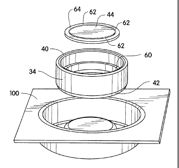
[00018] FIG. 1 illustrates a system for applying a microprotrusion
member to the stratum corneum. The system includes an impact applicator
10, a retainer 34, and a microprotrusion member 44. The applicator 10 is
preferably reusable while the retainer 34 and microprotrusion member 44 are
preferably for one time use. As shown in FIG. 1, the retainer 34 and
microprotrusion member 44 are packaged together in a preferably sterile
package 100 having a removable cover 102. After removing the cover 102, a
skin proximal end 13 of the applicator 10 is inserted in an open skin distal
end
40 of retainer 34 in order to removably mount the retainer 34 on the
applicator
10. Thus, the applicator 10 and the retainer 34 have a configuration which
allows the retainer to be mounted directly onto the applicator while still in
the
package 100.
[00019] Alternatively, the outer housing of retainer 34 can in part act as
the sealed package for microprotrusion member 44. In this embodiment the
open ends of retainer 34 are sealed by removable/peelable seals 150, as
shown in FIG. 13.
[00020] FIG. 2 is an exploded view of the microprotrusion member 44,
the retainer 34, and the package 100. The retainer 34 has a skin distal end
40 which is configured to engage the skin proximal end 14 of the applicator
10. A skin proximal end 42 of the retainer 34 provides a stratum corneum
contacting surface. The retainer 34 includes a shoulder 60, positioned
between ends 40 and 42, for mounting the microprotrusion member 44. The
7
CA 02425312 2003-04-11
WO 02/30300 PCT/US01/31837
microprotrusion member 44 is connected by frangible sections 62 to a ring 64
having an adhesive coated on a skin proximal surface thereof. Though shown
as a continuous circle, ring 64 could be configured instead as a plurality of
discontinuous tabs spaced circumferentially around member 44. The tabs
would be extensions of frangible sections 62 and partially extend peripherally
about member 44, the tabs being sufficient in number and area to properly
secure the tabs, member 44 and frangible sections 62 to retainer 34. The
microprotrusion member is shown more clearly in FIG. 7. The ring 64 having
adhesive is adhered to the shoulder 60 to secure the microprotrusion member
to the retainer 34, as shown in FIG. 6. In this manner, the patch 44 is
suspended in the retainer 34 and protected from unintentional contact by the
user.
[00021] According to one embodiment of the invention, the
microprotrusion member 44 includes a base material or web or a flexible
material having the microprotrusions mounted thereon. The web includes a
central section having the array of microprotrusions thereon. An adhesive
section of the web surrounds the central section and adheres the
microprotrusion member to the stratum corneum upon application. The web
also includes the frangible sections 62 surrounding the adhesive section and
an outer portion or ring 64 of web material located peripherally around the
frangible sections which is attached to the retainer 34. FIGS. 2 and 7
illustrate four evenly spaced frangible sections 62. However, other number
and arrangements of the frangible sections 62 may be used.
[00022] Other releasable mounting systems for mounting the
microprotrusion member 44 within the retainer 34, shown in FIGS. 8 to 10,
can be used as long as the force or energy needed to release the member 44
from the retainer 34 can be adequately provided by the energy source (in
applicator 10, the energy source is spring 20) in the applicator 10.
Alternative
means for releasably mounting microprotrusion member 44 within retainer 34
are illustrated in FIGS. 8 to 10 and include an interference fit in which the
member 44 is trapped by a pressed-in ring, friction fitting the member 44
within retainer 34, and adhering member 44 within retainer 34 using an
adhesive with a low bond strength.
8
CA 02425312 2003-04-11
WO 02/30300 PCT/US01/31837
[00023] FIG. 8 illustrates a retainer 34a having a press-in ring 154 which
traps an edge of a microprotrusion member 44a between shoulder 60a and
ring 154.
FIG. 9 shows a retainer 34b without a shoulder and a microprotrusion
member 44b which is relatively rigid and forms a press fit within the retainer
34b. FIG 9A shows retainer 34b with shoulder 60b at a point where the inner
diameter of retainer 34b has been enlarged. This is at a point slightly below
where microprotrusion member 44b has been press fit. This enlarged
diameter facilitates the release of microprotrusion member 44b once it has
been forced past the section of the narrow diameter.
FIG. 10 illustrates an alternative embodiment of a retainer 34c with an
inverted shoulder 60c having a microprotrusion member 44c attached to the
shoulder by a low bond strength adhesive which releases during application of
the microprotrusion member 44c to the stratum corneum. This embodiment
would require no frangible sections 62.
[00024] The manner in which the microprotrusion member 44 is
mounted in the retainer 34 and the location of the patch may vary. For
example, the microprotrusion member 44 may be positioned adjacent the skin
proximal end 42 of the retainer 34. In addition, the microprotrusion member
44 may be secured within the retainer 34 by trapping the ring 64 between two
cooperating parts of the retainer 34.
[00025] The retainer 34 is preferably attached to the applicator 10 after
cocking of the piston 14. The retainer 34 can be attached by a snap in
connection requiring less force to snap in than the force required to release
the piston.
[00026] The retainer 34 may also be attached to the applicator 10 by a
bayonet fitting (FIG. 14) which allows retainer 34 to twist onto the
applicator
body. Another to attached retainer 34 is a slide on fitting (FIG. 15) which
allows retainer 34 to slide onto the applicator body 12 in a direction normal
to
the axis of the applicator.
[00027] Yet another way of mounting the retainer within the applicator is
illustrated in FIG. 16. FIG. 16 illustrates another embodiment of a hand
operated spring-loaded applicator having an end 212 adapted to contact the
9
CA 02425312 2003-04-11
WO 02/30300 PCT/US01/31837
skin of the patient. Adjacent to end 212 is a slot 214 through which the
retainer 234 can be inserted. Like retainer 34, retainer 234 also has a ring-
shaped configuration. Mounted within the retainer 234 is a microprotrusion
member 244, which is connected to retainer 234 by a plurality of frangible
connects 262 which are connected to a plurality of tabs 264. Tabs 264 are
coated with adhesive on the skin proximal side which facilitates the
attachment of tabs 264 to retainer 234. A finger grip 236 is preferably
provided in one section of retainer 234 in order to provide a convenient place
for grasping retainer 234 and to help prevent inadvertent contact between the
user's fingers and the microprotrusions in member 244. After inserting the
retainer 234 into slot 214, the user places edge 212 against the skin surface
to be treated. Then, cap 216 is pressed towards the skin causing the piston
(not shown) to be released and impact the microprotrusion member 244
against the skin.
[00028] In order to apply a microprotrusion member 44 according to the
present invention, the package 100 of FIG. 1 is opened by removing the
releasable film cover 102. Then, the retainer 34 is attached to the applicator
10. An outside surface of the retainer 34 can be handled without contacting
the microprotrusion member 44. Thus, contamination of the microprotrusion
member 44 and inadvertent exposure of the physician, nurse, medical
technician or even the patient to the microprotrusions and any drugs
contained thereon, are prevented. The applicator device 10 with the retainer
34 mounted thereon is then ready for use to pierce the stratum corneum. The
skin proximal end 42 of the retainer 34 is placed against the stratum corneum
and pressed down with a force which causes piston 14 of the applicator to be
released. The microprotrusion member 44 is separated from the retainer 34
by the downward force of the piston 14 which fractures the frangible sections
62.
[00029] FIG. 3 illustrates one embodiment of a microprotrusion member
for use with the present invention. FIG. 3 shows a plurality of
microprotrusions in the form of microblades 90. The microblades 90 extend at
a substantially 90 angle from a sheet 92 having openings 94. The sheet 92
may be incorporated in an agent delivery patch or an agent sampling patch
CA 02425312 2009-02-26
which includes an agent reservoir and/or an adhesive for adhering the patch to
the stratum corneum. Examples of agent delivery and sampling patches which
incorporate a microprotrusion array are found in WO 97/48440, WO 97/48441,
WO 97/48442. The microprotrusion array of FIG. 3 without a reservoir may also
be applied alone as a skin pretreatment.
[00030] The term "microprotrusion" as used herein refers to very tiny
stratum corneum piercing elements typically having a length of about 10-500
pm,
and preferably about 50-400 pm, which make a penetration in the stratum
corneum. In order to penetrate the stratum corneum, the microprotrusions
preferably have a length of at least 10 pm, more preferably at least 50 pm.
The
microprotrusions may be formed in different shapes, such as needles, hollow
needles, blades, pins, punches, and combinations thereof.
[00031] The term "microprotrusion array" as used herein refers to a plurality
of microprotrusions arranged in an array for piercing the stratum corneum. The
microprotrusion array may be formed by cutting a plurality of blades from a
thin
sheet and folding each of the blades out of the plane of the sheet to form the
configuration shown in FIG. 3. The microprotrusion array may also be formed in
other known manners, such as by connecting multiple strips having
microprotrusions along an edge of each of the strips. The microprotrusion
array
may include hollow needles, for example hollow needles adapted to inject a
liquid
formulation.
[00032] Examples of microprotrusion arrays and methods of making same
are described in U.S. Patent Nos. 5,879,326 issued to Godshall, et al.,
3,814,097
issued to Ganderton, et al., 5,279,544 issued to Gross, et al., 5,250,023
issued to
Lee, et al., 3,964,482 issued to Gerstel, et al., Reissue 25,637 issued to
Kravitz,
et al., and PCT Publication Nos. WO 96/37155, WO 96/37256, WO 96/17648,
WO 97/03718, WO 98/11937, WO 97/48440, WO 97/48441, WO 97/48442, WO
98/00193, WO 99/64580, WO 98/28037, WO 98/29298, and WO 98/29365.
11
CA 02425312 2003-04-11
WO 02/30300 PCT/US01/31837
[00033] FIGS. 4 and 5 illustrate one exemplary embodiment of an
applicator 10 for use with the retainer 34 of the present invention. However,
other applicator configurations may also be used with the retainers which are
described herein.
[00034] The applicator 10 includes a body 12 and a piston 14 movable
within the body. A cap 16 is provided on the body 12 for activating the
applicator to impact the stratum corneum with the microprotrusion member
44. An impact spring 20 is positioned around a post 22 of the piston 14 and
biases the piston downward (i.e., towards the skin) with respect to the body
12. The piston 14 has an impact surface 18 which is substantially planar,
slightly convex, or configured to match the contours of a particular body
surface. The surface 18 of the piston 14 impacts the microprotrusion member
44 against the skin causing the microprotrusions 90 to pierce the stratum
corneum.
[00035] FIG. 4 shows the piston 14 in the cocked position. When the
applicator is cocked, the piston 14 is pressed up inside the body 12 and
locked in place by a locking mechanism. The locking mechanism includes a
stop 26 on the post 22 and a flexible finger 28 on the body 12 having a
corresponding stop 30. As the piston 14 is moved toward the body 12
compressing the impact spring 20, the stop 26 flexes the finger 28 and snaps
over the corresponding stop 30 of the flexible finger. The cocking step is
performed by a single compression motion which both cocks and locks the
piston 14 in the cocked position.
[00036] As shown in FIG. 4, in the cocked position, catch 26 and latch
30 on the piston 14 and body 12 are releasably engaged, preventing
downward motion of the piston in the body. FIG. 4 also illustrates the patch
retainer 34 mounted on the body 12.
[00037] The applicator 10 has been described for use with a
microprotrusion member 44. The microprotrusion member 44 may be a patch
which generally includes a microprotrusion array, an agent reservoir,
and a backing. However, the applicator 10 may also be used with a
microprotrusion member 44 without an agent reservoir. In this case, the
microprotrusion member is used as a pretreatment which is followed by the
12
CA 02425312 2003-04-11
WO 02/30300 PCT/US01/31837
application of an agent with a separate device. Alternatively, the
microprotrusion member 44 may incorporate the agent as a coating on the
microprotrusion array, e.g. for delivering a vaccine intradermally.
[00038] The activation of the applicator 10 by releasing the locking
mechanism is performed by downward force applied to the applicator cap 16
while the end 42 of the applicator is held against the skin. The cap 16 is
biased in a direction away from the skin by a hold down spring 24 which is
positioned between the body 12 and the cap. The cap 16 includes a pin 46
extending downward from the cap. When the cap 16 is pressed downward
against the bias of the hold down spring 24, the pin 46 contacts ramp 48 on
flexible finger 28 moving the flexible finger outward and disengaging latch 30
of the flexible finger 28 from catch 26. This releases piston 14 and the
piston
moves downward impacting the stratum corneum with the microprotrusion
member 44. The impact is applied substantially parallel to a central axis of
i5 the microprotrusion member 44.
[00039] FIG. 5 illustrates the applicator 10 after the device has been
activated and a microprotrusion member 44 has been applied to the stratum
corneum. The hold down spring 24 is selected such that a predetermined
hold down force must be achieved before the device is activated. The hold
down force causes the stratum corneum to be stretched by the surface 42 of
the retainer 34 so that the skin is under optimal tension at the time the
microprotrusion member 44 impacts the skin. The hold down force applied by
the hold down spring 24 is preferably selected to cause the surface 42 to
apply a tension to the skin in the range of about 0.01 to 10 megapascals
(MPa), more preferably about 0.05 to 2 MPa.
[00040] A balance between the hold down spring 24 and the impact
spring 20 allows the cocking of the piston 14 by pressing on the cap 16
without causing the finger 46 to release the locking mechanism. The impact
spring 20 is selected to achieve a predetermined impact which is appropriate
for a particular patch to provide the desired microprotrusion penetration. In
general, the microprotrusion member 44 is impacted against human skin with
a power of at least 0.05 joules per cm2 in 10 msec or less, preferably with
13
CA 02425312 2003-04-11
WO 02/30300 PCT/US01/31837
power of at least 0.1 joules per cm2 of microprotrusion member in 1 msec or
less.
[00041] The applicator 10 according to the present invention has been
described with respect to an orientation in which the skin proximal side of
the
device is shown at the bottom of the figures. It should be understood that the
applicator device may be used in other orientations (e.g., sideways or upside
down) from that shown in the figures.
[00042] FIGS. 11 and 12 illustrate an alternative embodiment of the
invention including a retainer 134 which is releasably mounted on a piston
122 of the impact applicator 110. The retainer 134 includes a disk shaped
head 136 and a shaft 138. The shaft 138 includes a detent 140 or projection
which allows the shaft to snap into a corresponding recess 142 in piston 122
of the applicator 110. The disk shaped head 136 has a microprotrusion
member application surface 137 with the microprotrusion member releasably
fixed to the application surface 137 by adhesive or other means. If adhesive
is used to fix the microprotrusion member 144 to the retainer 134, the
adhesive used holds the microprotrusion member less securely than an
adhesive which secures the microprotrusion member 144 to the skin. A
package 100 avoids damage to the microprotrusion member 144 during
shipping and storage and also can serve the function of a release liner.
[00043] In order to apply a microprotrusion member 144 according to the
embodiment of FIGS. 11 and 12, the package 100 is opened by removing the
releasable film cover 102. Then the retainer 134 is attached to the applicator
device 110 by inserting the shaft 138 into the recess 142 in the applicator
device 110. The package 100 is then removed leaving retainer 134
releasably engaged to applicator device 110. Applicator device 110 is now
ready for application of the microprotrusion member 144 to the stratum
corneum. The microprotrusion member 144 is then applied to the stratum
corneum by the impact applicator device 110. The applicator device 110 and
the attached retainer 134 are moved away from the stratum corneum leaving
the microprotrusion member 144 impacted on the stratum corneum.
[00044] The device of the present invention can be used in connection
with agent delivery, agent sampling, or both. In particular, the device of the
14
CA 02425312 2003-04-11
WO 02/30300 PCT/US01/31837
present invention is used in connection with transdermal drug delivery,
transdermal analyte sampling, or both. Transdermal delivery devices for use
with the present invention include, but are not limited to passive devices,
osmotic devices, pressure-driven devices, and electrotransport devices.
Transdermal sampling devices for use with the present invention include, but
are not limited to, passive devices, negative pressure driven devices, osmotic
devices, and reverse electrotransport devices. The transdermal devices of
the present invention may be used in combination with other methods of
increasing agent flux, such as skin permeation enhancers.
[00045] The device of the present invention may be used with a
microprotrusion array included in a transdermal delivery or sampling patch
having adhesive for attaching the patch to the skin. Alternatively, the
microprotrusion member and delivery or sampling patch may be two separate
elements with the microprotrusion member used for pretreatment prior to
application of the delivery or sampling patch.
[00046] While the invention has been described in detail with reference
to the preferred embodiments thereof, it will be apparent to one skilled in
the
art that various changes and modifications can be made and equivalents
employed, without departing from the present invention.