Note: Descriptions are shown in the official language in which they were submitted.
CA 02425326 2003-04-08
WO 02/36191 PCT/USO1/46203
TITLE OF THE INVENTION
HEAT AND MOISTURE EXCHANGER
ADAPTOR FOR CLOSED SUCTION CATHETER
ASSEMBLY AND SYSTEM CONTAINING THE SAME
Field of the Invention
The present invention relates generally to respiratory catheter
systems utilizing a heat and moisture exchanger, and particularly to an
adaptor for use in such systems.
Backgiround of the Invention
There are a number of different circumstances in which it is
necessary for a person to have an artificial airway, such as a
tracheostomy tube, placed in his or her respiratory tract. As used
herein, the phrase "artificial airway" includes devices such as
tracheostomy tubes, endotracheal tubes and the like. Artificial airways
keep the patient's natural airway open so that adequate lung ventilation
can be maintained. In particular situations, the artificial airway must be
left in the patient for a prolonged period of time. For example, many
persons suffering severe neck or head trauma use a tracheostomy
tube in conjunction with mechanical ventilation during extended
. recovery and rehabilitation periods.
When an artificial airway is used, it is critical that respiratory
secretions be periodically removed. This is typically accomplished by
the use of a respiratory suction catheter that is advanced into and
through the tracheostomy tube. As the suction catheter is withdrawn, a
negative pressure (or vacuum) is applied to draw mucus and other
secretions from the patient's airways and the interior of the artificial
airway. While a substantial amount of mucus and other secretions will
be withdrawn through the lumen of the suction catheter, a portion of
the mucus and other secretions will remain as a film on the outside of
the catheter.
i
In a closed suction catheter assembly (for example as set forth
in U.S. Patent Nos. 3,991,762 and 4,569,344), the catheter may be
CA 02425326 2003-04-08
WO 02/36191 PCT/USO1/46203
2
enveloped by a protective sleeve and include a valve mechanism
disposed near the vacuum source. These features reduce the risk of
contamination to both the patient and the care-giver.
In normal breathing, the structures of the nose and sinus
passages serve to heat and moisturize inhaled air. In situations where
a patient requires mechanical ventilation on a periodic basis, it is
common to place a heat and moisture exchanger (HME) on the
proximal end of the artificial airway after removal of the mechanical
ventilator. This type of placement is commonly done with patients who
are able to breathe on their own for an extended period of time. In
such systems and as used herein, "proximal" refers to the direction
toward the clinician and "distal" refers to the direction toward the
patient.
The HME is intended to replicate these functions, of heating and
moisturizing air, in patients having artificial airways. The HME is
adapted to reduce heat and moisture loss from the respiratory system
of the patient as the patient breathes. This is done by retaining within
the HME heat and moisture from air which is exhaled through the
HME, and by warming and moisturizing air that is inhaled through the
HME. The HME typically includes a material, such as porous foam,
that is enclosed within a housing or other structure.
To date, most HMEs have not been used in conjunction with a
closed suction catheter assembly. Thus, prior to suctioning respiratory
secretions from a patient, it may be necessary to remove the HME
from the proximal end of the artificial airway so that a suctioning
catheter may be advanced to the patient's natural airways. Removal
and attachment of the HME often causes discomfort to the patient and,
during the period in which the HME has been removed, the patient is
deprived of heat and moisture exchange and may be deprived of
supplemental oxygen, if used.
Thus, there is a need for an inexpensive adaptor that enables a
closed suction catheter to be easily and quickly attached to and
CA 02425326 2003-04-08
WO 02/36191 PCT/USO1/46203
3
removed from an HME that is mounted to an artificial airway while
minimizing patient discomfort.
Summary of the Invention
Various features and advantages of the invention will be set
forth in part in the following description, or may be obvious from the
description, or may be learned through practice of the invention.
The present invention is generally directed to an adaptor for
connecting a closed suction catheter assembly to an HME mounted on
an artificial airway, such as a tracheostomy tube. In addition, the
present invention is directed to a closed suction catheter system
containing the adaptor and a closed suction catheter assembly. The
adaptor of the present invention does not interfere with patient
breathing.
The adaptor has a first end that is adapted to be in
communication with the closed suction catheter assembly. The
adaptor may be removably or non-removably engaged with the
catheter assembly. The adaptor also has a second end which is
adapted to engage the heat and moisture exchanger. Further, there is
a channel formed through the adaptor. This channel allows an
aspirating catheter of the closed suction catheter assembly to be
moved through the adaptor. The aspirating catheter can then also be
moved through an aperture formed through the heat and moisture
exchanger.
An adaptor cover may also be provided for use with the closed
suction catheter system. The cover is configured to selectively isolate
the closed suction catheter assembly from the environment, and to
facilitate cleaning of the catheter after suctioning.
The present invention may also provide an alternative
embodiment of an adaptor for connecting a closed suction catheter
assembly to an HME. The adaptor includes a first end configured for
attachment to a closed suction catheter assembly, and a second end
including a retainer capable of engaging the HME. The adaptor is
CA 02425326 2003-04-08
WO 02/36191 PCT/USO1/46203
4
configured for advancement of a catheter therethrough. The retainer
may include a ring, for example a circular or elliptical ring member,
having a wall configured to encircle and releasably engage the HME.
Furthermore, if a ring retainer is included in the adaptor, the ring
may include a pair of oppositely disposed apertures located on first
and second portions of the ring. The apertures are configured to
engage the HME. Moreover, the retaining ring may also include bowed
outward third and fourth portions oppositely disposed from each other
on the ring with the bowed outward third and fourth portions disposed
between the first and second portions on the ring. These bowed third
and fourth portions may be configured such that, as they are urged
inwardly toward each other, the first and second portions are urged to
move outwardly away from the HME, thereby disengaging the first and
second portions from the HME.
The retainer of the adaptor may be formed such that the first
portion and the second portion are defined by apertures for receiving
external projections of the HME. Alternatively, the retainer may
include at least one L-shaped channel configured for receiving external
projections of the HME. In one embodiment, the adaptor may also
include an annular projection configured for engaging a valve in the top
of the HME.
The present invention may also form an adaptor assembly for
connecting a closed suction catheter assembly to an HME. The
adaptor assembly includes an adaptor having a first end configured for
attachment to a closed suction catheter assembly; and a second end
including a retainer configured for engaging the HME and positioning
the closed suction catheter assembly with respect to the HME. The
adaptor is configured for advancement of a catheter therethrough. The
adaptor assembly may also contain an annular projection defining a
channel through which a catheter of the closed suction catheter
assembly may be advanced. The adaptor assembly may also include
an adaptor cover configured for attachment to the annular projection.
CA 02425326 2003-04-08
WO 02/36191 PCT/USO1/46203
The adaptor cover can take on various configurations. For
example, the cover may have a cylindrical wall formed therein with at
least one opening formed in the wall. A cap may be provided with the
cover for covering the opening.
5 ~ In another embodiment, the adaptor assembly includes at least
one arm formed in the retainer, wherein the arm is capable of
engaging the HME. For example, the retainer may include at least two
arms oppositely disposed from each other wherein each arm is
capable of engaging the HME.
In addition, at least one arm may include an aperture capable of
receiving a projection of the HME. Furthermore, at least one arm may
include a surface member capable of engaging the HME. The adaptor
assembly may include a base formed in the retainer wherein each arm
is pivotally connected to a base.
The present invention is also directed to a closed suction
catheter system. This system includes a closed suction catheter
assembly having a catheter and a protective sleeve enveloping the
catheter. The closed suction catheter assembly includes a distal end;
and an adaptor connected to this distal end capable of engaging a
proximal end of an HME.
Brief Description of the Drawingis
FIG. 1 is a perspective view of a heat and moisture exchanger
(HME) in accordance with the teachings of the prior art;
FIG. 2 is a perspective view of another HME in accordance with
the teachings of the prior art;
FIG. 3 is a perspective view of an adaptor of the present
invention;
FIG. 4 is another perspective view of the adaptor shown in Fig.
3 in conjunction with an HME;
d FIG. 5 is a perspective view of an HME and an adaptor
positioned with respect to each other so that they may be easily
connected to one another;
CA 02425326 2003-04-08
WO 02/36191 PCT/USO1/46203
6
FIG. 6 is a perspective view of the adaptor shown in FIG. 5 with
the HME nested within the adaptor;
FIG. 7 is a partial cross-sectional view of the adaptor and HME
shown in FIG. 6 taken along line 7-7 of FIG. 6, wherein the HME is
mounted on an artificial airway, the artificial airway not being shown in
FIG. 6;
FIG. 8 is a perspective view of an HME with the cover of the
housing removed;
FIG. 9 is a perspective view of an alternate embodiment of an
adaptor made in accordance with the present invention;
FIG. 10 is a perspective view of the invention shown in FIG. 9
with the adaptor mounted on the HME;
FIG. 11 is a perspective view of yet another embodiment of an
adaptor made in accordance with the present invention;
FIG. 12 is a perspective view of another embodiment of the
invention wherein the arms of the adaptor are equipped with
projections or barbs for engaging the housing of the HME;
FIG. 13 is a perspective view of the embodiment described in
FIG. 12 mounted on an HME;
FIG. 14 is a side view of a closed suction catheter system with
an adaptor and an adaptor cover;
FIG. 15 is a perspective view of an alternate embodiment of an
adaptor cover for use with the adaptor of the present invention;
FIG. 15A is a perspective view of the adaptor cover of FIG. 15
shown attached to the adaptor of the embodiment of FIG. 11; and
FIG. 16 is a perspective view of yet another embodiment of an
adaptor cover for use with the adaptor of the present invention.
Detailed Description
Reference will now be made in detail to embodiments of the
invention, one or more examples of which are shown in the drawings.
It should be appreciated that each example is provided by way of
explaining the invention, and not as a limitation of the invention. For
CA 02425326 2003-04-08
WO 02/36191 PCT/USO1/46203
7
example, features illustrated or described with respect to one
embodiment may be used with another embodiment to yield still a
further embodiment. Such modifications and variations are within the
scope and spirit of the invention.
The invention relates to a closed suction catheter assembly. At
its distal end, which is the end nearest the patient once a closed
suction catheter is attached, the closed suction catheter may be
attached to an artificial airway via one of a variety of connectors,
including, for example, a multi-legged tracheostomy connector. One of
the legs of the tracheostomy connector may be connected to a
tracheostomy tube. With the use of the closed suction catheter
assembly, the ventilating circuit need not be detached from the patient
during suctioning, and a single catheter may be used for an extended
period, typically a 24-hour period. The patient may need to have the
air drawn in through the artificial airway heated and moistened since air
is no longer traveling through the nose, sinuses, or throat. To
accomplish this task, it is commonly the case that a heat and moisture
exchanger be placed in the respiratory system.
A representative heat and moisture exchanger (HME) is shown
in FIG. 1 at 20. As illustrated therein, the HME includes a housing 22
with a porous material 24 disposed within the housing. The porous
material 24 is designed to reduce heat and moisture loss as the patient
breathes. Heat and moisture within exhaled air is retained within the
porous material 24. The inhaled air is warmed and humidified as the
inhaled air passes through the porous material 24. The porous
material 24 is typically a foam material that has sufficient porosity to
reduce the loss of heat and moisture from the patient. The material is
sometimes treated with a hygroscopic salt to enhance performance.
The housing 22 includes a bottom port 26 for receiving an exposed
end of a tracheostomy tube or other artificial airway.
The HME 20 also includes a side port 28 that may connect to an
oxygen supply line to administer oxygen to the patient. Oxygen may
CA 02425326 2003-04-08
WO 02/36191 PCT/USO1/46203
8
be required by those, for instance, with emphysema and other
diseases that cause damage to the lung tissue.
FIG. 2 shows an additional conventional heat and moisture
exchanger that is available from Datex-Ohmeda of Helsinki, Finland.
The HME, generally indicated again at 20 , includes a housing 22
having ridges 30 , and a top surface 32 that forms the upper portion of
the housing 22. In some embodiments, the top surface 32 is
configured as a removable cover that engages the housing 22. The
ridges 30 enable a clinician to securely hold the housing while the
housing 22 is being attached to or removed from a tracheostomy tube
or other artificial airway. The housing 22 also includes an enclosure 34
into which material, such as the material 24, may be placed. The
housing 22 further includes a bottom port 26, which is used to connect
the HME 20 to a tracheostomy tube or other artificial airway. Further,
the HME 20 may include a side port 28.
Disposed in alignment with the bottom port 26 is a top port 36
that is positioned in the center of the top surface 32. The bottom port
26 and the top port 36 are ends of a control aperture. The top port 36
is covered by a plurality of triangular-shaped projections 38 which are
pivotably attach to the top surface 32 to enclose the top port 36 and
form a valve 40. During attachment of the HME to an adaptor 42
(described in greater detail below), an annular projection of the adaptor
44 (see FIGS. 3, 5, and 9) contacts the triangular-shaped projections
38 causing the projections 38 to be deflected away from the annular
projection 44 and open the valve 40. The projections 38 may be
deflected toward either the enclosure 34 of the housing 22 or away
from the housing 22. Thus, in practice, a clinician can suction a patient
using the HME 20 by advancing a catheter (not shown) through the top
port 36 and into the tracheostomy tube or artificial airway (not shown).
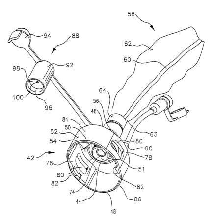
FIG. 3 shows a perspective view of an adaptor, generally
indicated at 42, made in accordance with the principles of the present
invention. The adaptor 42 has a proximal side 46 that is the side of the
CA 02425326 2003-04-08
WO 02/36191 PCT/USO1/46203
9
adaptor 42 that is attached to a closed suction catheter assembly 58.
The adaptor 42 may be an integral or non-removable component of the
catheter assembly 58 or can be configured to be releasably engaged
to the closed suction catheter assembly 58 by means commonly known
in the art. The adaptor 42 also has a distal side 48 that is configured
for attachment to an HME (not shown).
The adaptor 42 includes a base 50 and a retaining structure
configured with the base. In this embodiment, the retaining structure is
a retainer 52 attached to the base 50 by at least two arms 54. As
shown in FIG. 3, the retainer 52 takes the form of a retaining ring. The
base 50, in turn, is connected to the distal end 56 of the closed suction
catheter assembly 58. The closed suction catheter assembly 58 is
shown fully in FIG. 14 and is partially shown in FIG. 3. The assembly
includes an elongated aspirating catheter 60, an elongated protective
sleeve 62 surrounding the catheter 60, and a coupling 64 which
receives catheter 60 and secures the distal end 63 of the protective
sleeve 62, thereby sealing the protective sleeve 62 about the catheter
60. The catheter 60 can be advanced through the coupling 64 and into
an artificial airway such as a tracheostomy tube (not shown) of a
patient to suction mucus and other secretions from the patient's
respiratory system. The closed suction catheter assembly 58 also
includes, as shown in FIG. 14, a proximal end 66 and a proximal
coupling 68 which retains the proximal end 70 of the protective sleeve
62 in position. The closed suction catheter assembly 58 also includes
a valve mechanism 72 for selectively supplying suction through
elongate aspirating catheter 60.
Referring now to FIG. 3, an annular projection 44 is disposed on
the distal side 51 of base 50. The annular projection 44 surrounds a
channel 74 through which the aspirating catheter 60 is advanced. As
will be explained in more detail below, the annular projection 44
extends through the valve 40 (FIG. 2) of the HME 20 when the adaptor
42 is attached to the HME 20 . Thus, the annular projection 44 is
CA 02425326 2003-04-08
WO 02/36191 PCT/USO1/46203
configured to hold open the projections 38 (FIG. 2). Such a
configuration reduces the risk of mucus accumulating in HME 20 , as
the projections 38 are sufficiently distant from the catheter 60 so that
mucus is not removed from the catheter 60 by the projections 38. If
5 mucus accumulates in and is allowed to remain in the HME ~20 , it may
interfere with the patient's breathing.
In one embodiment, the retainer 52 may be an annular or
elliptical wall and form four sections. As shown in FIG. 3, two of the
four sections of the retainer 52, a first section 76 and a second section
10 78, are disposed on opposing sides of the retainer 52 and may be
provided with an attachment mechanism 80 for attaching the retainer
52 to the HME (not shown). In the embodiment shown in FIG. 3, the
retaining mechanism 80 is an aperture 80 that is formed in the first and
second sections 76 and 78, respectively, of the retainer 52. The
apertures 80 are sized to engage the ridges 30 of the HME 20 . In
some embodiments, a guide notch 82 (shown in FIG. 3) may be
formed in first and second sections 76 and 78, respectively, to help
guide the ridges 30 into the aperture 80. Once the ridges 30 are
retained by the apertures 80, the adaptor 42 is securely attached to the
HME 20.
The two remaining sections of the retainer 52 may include, in
selected embodiments, a third section 84 and a fourth section 86
which, as shown in FIG. 3, may be bowed outwardly and away from
first and second sections 76 and 78, respectively. The third section 84
and the fourth section 86 are situated between the first and second
sections 76 and 78, respectively. When the clinician desires to remove
the adaptor 42 from the HME 20 , he or she needs only to press the
third and fourth sections 84 and 86, respectively, toward each other.
This forces the retainer 52 to deform slightly and causes the first and
second sections 76 and 78, respectively, to move outwardly and away
from the HME 20 . Movement of the sections 76 and 78 causes the
apertures 80 to move a sufficient distance away from the ridges 30 so
CA 02425326 2003-04-08
WO 02/36191 PCT/USO1/46203
11
that the ridges 30 are no longer nested therein and engaged thereby.
Thus, the retainer 52 can be removed from the HME 20 without torque
or force being applied to the HME or the artificial airway. The ability to
remove the closed suction catheter assembly 58 without applying any
torque to the artificial airway is important, as a small amount of torque
can cause irritation and discomfort to the patient. In some instances,
the closed suction catheter assembly may be used numerous times a
day. In these instances, a small amount of irritation can lead to
increased patient discomfort.
Because the closed suction catheter assembly 58 may often be
removed, an adaptor cover 88 may be provided. When the catheter
assembly 58 is removed, it is important that the catheter assembly 58
be properly cleaned prior to removal via the lavage port 90. It is also
important that the aspirating catheter 60 be positioned within the
channel 74 when the catheter assembly 58 is removed from the
patient. Even if the aspirating catheter 60 extends out of the channel
74 and has not been cleaned properly, the use of an adaptor cover 88
can help to prevent contamination of the aspirating catheter 60.
As shown in FIG. 3, an exemplary adaptor cover 88 may be
formed to include a first portion 92 and an end cap 94. The first
portion 92 includes an elongated cylinder 96 with a wall 98 formed
through the middle of the cylinder. A small opening 100 may be
formed in the wall 98 to allow a very small amount of air into the first
portion 92. Thus, the first portion 92 may be attached to the annular
projection 44 after removal of the closed suction catheter assembly 58
after each suctioning procedure. If the adaptor 42 is fixed to the
catheter assembly 58, then cover 88 must be configured so that first
portion 92 has a sufficient length to extend into the adaptor 42. Once
the aspirating catheter 60 has been cleaned, the end cap 94 may
further be used to cover the opening 100 in the first valve portion 92.
FIG. 4 shows a perspective view of the adaptor 42 and the HME
20 from the proximal or care-giver end of the closed-suction catheter
CA 02425326 2003-04-08
WO 02/36191 PCT/USO1/46203
12
assembly 58. FIG. 5 shows a close-up side view of the orientation of
the adaptor 42 and the HME 20 . FIGS. 4 and 5 show the alignment
between the ridges 30 of the HME 20 and the apertures 80 of the
retaining ring 52 of the adaptor 42. With the ridges 30 and the
retaining ring 52 in alignment with each other, the adaptor 42 need only
be moved downwardly until the ridges 30 snap into the apertures 80
for the HME 20 to be held securely to the adaptor 42. The clinician
may assist this process by pressing the third and fourth sections 84
and 86, respectively, toward each other to enable the ridges 30 to
more easily engage the apertures 80. Alternatively, the housing 22 of
the HME 20 may be flexed to slightly deform the housing 22 to enable
the ridges 30 to more easily engage the apertures 80. Once the ridges
30 are retained within the apertures 80, the housing may be allowed to
return to its original position.
To release the adaptor 42 from the HME 20 , the third and
fourth sections 84 and 86, respectively, of the retaining ring 52 need
only be squeezed momentarily to move the first and second sections
76 and 78, respectively, outwardly. This movement releases the ridges
30 from the apertures 80 and allows HME 20 to be disengaged from
the adaptor 42.
FIG. 6 is a close-up perspective view of the HME 20 seated
within and engaged to the adaptor 42. As shown therein, the ridges 30
of the HME 20 are nested in the apertures 80 in the first and second
sections 76 and 78, respectively, so that the retaining ring 52 is held
securely to the HME 20 . Because the apertures 80 in the retaining
ring 52 are wider than the ridges 30, the adaptor 42 is able to rotate
slightly in either direction. If desired, the apertures 80 could be made
virtually the same size as the area covered by ridges 30 to reduce or
prevent such rotation. ,
FIG. 7 is a side partial cross-sectional view of the HME 20 and
the adaptor 42 taken along line 7-7 in FIG. 6 through the ridges 30 and
the apertures 80, as well as a fragmented view of the HME mounted
CA 02425326 2003-04-08
WO 02/36191 PCT/USO1/46203
13
on a tracheostomy tube 102. The adaptor cover 88 is not shown in this
view. As shown in FIG. 3, the annular projection 44 is configured to
engage the projections 38 of the valve 40 of the HME 20 so that the
projections are moved to an "open" position, which is shown in FIG. 7,
upon attachment of the adaptor 42 to the HME 20 . If the projections
38 were to engage the aspirating catheter 60 as it is retracted from the
tracheostomy tube 102, mucus and other secretions could be scraped
from the aspirating catheter 60 by the projections 38. Such secretions
would remain in the HME 20 and could drip back into the tracheostomy
tube or coat the porous material 34 in the HME 20 and potentially
interfere with the patient's breathing. By keeping the projections 38 in
the "open" position, the annular projection 44 allows the mucus to
remain on the aspirating catheter 60 until the aspirating catheter 60
engages a seal 104 of the closed suction catheter assembly 58. The
seal 104, as shown in FIG. 7, is disposed within the closed suction
catheter assembly 58 and engages the aspirating catheter 60 as the
catheter is moved through the center of the annular seal 104. Mucus
is stripped from the aspirating catheter 60 by the seal 104 as the
aspirating catheter passes through the center of the annular seal 104.
FIG. 8 shows a perspective view of an HME 20 having a
removable top surface or cover. The HME 20 shown in FIG. 8 includes
a pair of flange keys 106 that are disposed near the top opening 108 of
the HME 20, the flange keys 106 being disposed oppositely from each
other along the exterior of the HME 20. The flange keys 106 may be
offset from the ridges 30. For example and as shown in FIG. 8, the
flange keys 106 may be offset 90 degrees from the ridges 30. The
flange keys 106 may be configured to fit between the HME housing 22
and the third and fourth sections 84 and 86, respectively, of the
retaining ring 52 when the adaptor 42 is attached to the HME 20 . The
flange keys 106 help to prevent the clinician or care giver from
inadvertently orienting the adaptor 42 on the HME 20 so that the
apertures 80 of the retaining ring 52 are not aligned with the ridges 30.
CA 02425326 2003-04-08
WO 02/36191 PCT/USO1/46203
14
If the retaining ring 52 is not in the proper orientation, the first and
second sections 76 and 78, respectively, will engage the flange keys
106 and prevent improper attachment of the HME 20 to the adaptor
42.
~ While discussed with respect to FIGS. 4 through 8 as being a
retaining ring, those skilled in the art will appreciate that the retainer 52
need not be in the form of a ring. For example, the third and fourth
sections 84 and 86, respectively, could be omitted from the retainer. In
such an embodiment, the first and second sections 76 and 78,
respectively, will engage the HME 20 . In such a configuration, a
flange may be provided on each of the first and second sections 76
and 78, respectively. The flange would permit the first and second
sections 76 and 78, respectively, to be urged away from the HME 20
when the closed suction catheter assembly 58 is to be disengaged
from the HME 20.
Turning now to FIG. 9, there is shown therein a perspective view
of an alternative embodiment of an HME adaptor, generally indicated
at 42, made in accordance with the principles of the present invention.
As illustrated in FIG. 9, the retainer may be formed as a cup-shaped
housing 110, the distal portion 112 of the housing 110 forming a
retaining ring for encircling the HME 20 . An L-shaped port or channel
114 extends into the housing 110 to receive the ridges 30.
In the embodiment depicted in FIG. 9, the ridges 30 are initially
aligned with the first end 116 of the L-shaped channel 114. Once the
ridges 30 have been sufficiently advanced into the L-shaped channel
114, the cup-shaped housing 110 can be rotated to place the ridges 30
at the second end 118 of the channel 114, as shown in FIG. 10. Once
the ridges 30 are secured at the end 118 of L-shaped channel 114, the
closed suction catheter assembly 58 can be used in the conventional
manner.
The ridges 30 at the end 118 of the channel 114 may be
maintained in place in a variety of ways, including friction, or a lip 120
CA 02425326 2003-04-08
WO 02/36191 PCT/USO1/46203
(Fig. 10) or another mechanism which inhibits inadvertent counter-
rotation and thus removal of the ridges 30 from the channel 114. FIG.
10 illustrates the interlocking arrangement of the HME 20 and the
adaptor 42. Those skilled in the art will appreciate that there are
5 numerous holding mechanisms that can be used in such a channel.
These include, but are not limited to, a nonlinear path within the
channel, a skid resistant surface along some portion of the channel, as
well as a snap-fit or press-fit engagement between the channel and the
ridges 30.
10 As with the embodiments shown in FIGS. 3 and 9, adaptor 42
includes an annular projection 44 through which the aspirating catheter
60 may be advanced. The annular projection 44 holds open the
projections 38 that form the valve 40 in the HME 20 , thus preventing
mucus from being deposited in the HME 20 .
15 Turning now to FIG. 11, there is shown an alternate
embodiment of an HME adaptor 42 made in accordance with the
principles of the present invention. The adaptor 42 is disposed at the
distal end of the closed section catheter assembly 58. The adaptor 42
includes a retainer formed by first and second arms 122 and 124,
respectively, which are pivotally attached to the base 50. A distal
portion 126 and 128 of each arm 122 and 124, respectively, extends in
the distal direction (toward the patient) away from the base 50. The
distal portions 126 and 128 of each arm provides a mechanism for
holding the closed suction catheter assembly 58 to the HME 20 .
Although a wide variety of mechanisms may be used to hold the
catheter assembly 58 to the HME 20 , the embodiment shown in FIG.
11 utilizes a pair of apertures 130 formed in the first and second arms
122 and 124, respectively, to receive the ridges 30 of the HME 20 .
Other mechanisms that may be suitable include placing a high friction
material, shown at 132 in FIG. 11, such as rubber, to provide frictional
engagement between the housing 22 of the HME 20 and the adaptor
42.
CA 02425326 2003-04-08
WO 02/36191 PCT/USO1/46203
16
A pair of proximal portions 134 and 136 of the first and second
arms 122 and 124, respectively, extend away from the base 50 in the
proximal or clinician direction, and provide levers for pivoting the first
and second arms 122 and 124, respectively, away from the HME
housing 22. To ensure a secure fit between the HME 20 and the
adaptor 42, the arms 122 and 124 may be biased toward each other so
that the distance between the distal ends 128 and 126 of the arms may
be smaller than the diameter of the HME housing 22. When
configured in this manner, the arms 122 and 124 will firmly engage the
HME 20 and help to reduce accidental dislocation of the HME 20 .
FIG. 12 and FIG. 13 show a perspective view of yet another
embodiment of the HME adaptor 42 that is attached to a closed
suction catheter assembly 58 and an HME 20 . The closed suction
catheter assembly 58 is configured similarly to those shown in FIGS. 5
and 11 and is therefore numbered accordingly.
The adaptor 42 includes a retainer formed by a first arm 122
and a second arm 124 that are pivotally attached to the base 50. The
distal portion 126 and 128 of each arm 122 and 124, respectively, may
have one or more barbs or projections 138, which are configured to
engage the housing 22 of the HME 20 . The projections 138 nest in
the HME housing 22 to secure the adaptor 42 to the HME 20 .
Each arm 122 and 124 has a proximal portion 134 and 136,
respectively, which is disposed on the end which is opposite of the
distal portion of each of the respective arms. By pressing the proximal
sections 134 and 136 toward each other, the distal portions 126 and
128 of the arms 122 and 124, respectively, and the accompanying
projections 138, can be moved away from each other to enable the
adaptor 42 to move relative to the HME 20 . Each of proximal
sections 134 and 136 may have a concave portion 140 or may be
otherwise shaped to facilitate gripping by the care-giver for receiving
the fingers of the clinician. For example, the clinician may place his or
her thumb in one concave portion 140 and forefinger in the opposing
CA 02425326 2003-04-08
WO 02/36191 PCT/USO1/46203
17
concave portion. By pressing the thumb toward the forefinger, the
proximal portions 134 and 136 are moved together and the distal
portions of the arms 126 and 128 are moved apart.
To mount the adaptor 42 on the HME 20 , the arms 122 and
124 can be pivoted as described above. However, by providing an
appropriate taper to the distal end of the projections 138, the arms 122
and 124 can be made to move outwardly as the adaptor is advanced
onto the housing. Once the projections 138 pass the upper rim 23 of
the housing 22, the projections 138 will return to their original position
and secure the catheter assembly 58 to the HME 20 .
FIG. 14 shows a side view of a closed suction catheter system
containing a closed suction catheter assembly 58 with an HME adaptor
42 and an alternate embodiment of the adaptor cover 88. The cover
88 may be attached to the valve 72 of the closed suction catheter
assembly 58, but may be otherwise attached to the closed suction
catheter assembly 58. The cover 88 has a first valve portion (not
shown) which is substantially the same as the first portion 92 that is
shown in FIGS. 3-9. The cover 88 as shown in FIG. 14 allows the
closed suction catheter assembly 58 to form a loop with the adaptor
42. When the catheter assembly 58 is not being used, the ability to
form the catheter assembly 58 and the adaptor 42 into a loop allows
the catheter assembly 58 to be conveniently hung somewhere out of
the way of the care-giver and the patient, but available for immediate
use. FIG. 14 does not show such a loop, but instead shows cover 88
25' being unattached to adaptor 42.
FIG. 15 shows a perspective view of an alternate embodiment of
the adaptor cover 88. The cover 88 shown in FIG. 15 covers the
annular projection 44 and can be configured to decrease the risk of
contamination. The cover 88, as shown therein, also includes a clip
142 that allows the cover 88 to be easily and conveniently attached to
and removed from other structures, such as, for example, the
CA 02425326 2003-04-08
WO 02/36191 PCT/USO1/46203
18
protective sleeve 62, the aspirating catheter 60, or to nearby
structures, such as, for example, a stand.
FIG. 15A shows the adaptor cover 88 attached to an HME
adaptor 42. While the HME adaptor is the embodiment described in
FIG. 11, it is to be understood that the adaptor cover 88 can be
attached to any embodiment of the present invention.
Finally, FIG. 16 shows yet another embodiment of the adaptor
cover 88 which may be used in accordance with the teachings of the
present invention. The adaptor cover 88 shown therein includes a
portion that attaches to the annular projection 44 and is geometrically
configured in a manner similar to the embodiment of the adaptor cover
88 depicted in FIG. 6. The cover 88 shown in FIG. 16 includes a tube
144 that is configured at a first end 146 for attachment to a suction
canister 148. The second end 150 of the tube 144 may be capped, or
may have suction tubing or a feed line attached thereto.
While the invention has been described in detail with respect to
specific embodiments thereof, it will be appreciated that those skilled in
the art, upon attaining an understanding of the foregoing may readily
conceive of alterations to, variations of and equivalents to these
embodiments. Accordingly, the scope of the present invention should
be assessed as that of the appended claims and any equivalents
thereto.