Note: Descriptions are shown in the official language in which they were submitted.
CA 02425374 2003-04-14
ADJUSTABLE FOUR PLATE ASSEMBLY FOR A CHAIR
Field of the Invention
This invention relates in general to an assembiy that can be used for
adjusting a variety of components of a chair and more particularly to an
adjustable four plate assembly that can adjust various components of a chair
and more specifically the armrest of a chair in isolated motions or motions in
io conjunction with one another, namely, side to side in a lateral movement,
pivoting in an arc like motion and sliding forwards and backwards in a
longitudinal movement.
Background of the Invention
The ability to adjust a chair to provide maximum comfort for the user is
a primary concern for the ergonomics discipline. As users and chairs come in
all shapes and sizes, the ability to accommodate each user to each chair has
become important to the comfort and productivity of the user. This issue is of
2o particular importance for those individuals that use computers and/or spend
considerable lengths of time sitting. Therefore adjustable armrests, backs,
the height of the chair and various other positions have been addressed in a
wide variety of inventions to improve on comfort and accommodate the user's
desires.
For example, United States Patent No. 5,971,484 issued on October
26, 1999 to Lambert et al relates to an adjustable armrest for chairs that
includes a support plate that is rotatable about the main pivot to adjust the
angular orientation of the armrest construction and is laterally movable along
continuously parallel positions to adjust the width of the armrest
construction
relative to the chair.
CA 02425374 2003-04-14
-2-
Tornero is the owner of U.S. Patent No. 5,586,811 which, was issued
on December 24, 1996 and this patent relates to an adjustment device for
selectively positioning a structural member such as an office chair arm
relative
to the seat. The device includes a planar support member and a retaining
member which are joined to encase a bearing through which a slidable
structural member is adjusted. The device allows for laterally positioning the
arms of a chair to accommodate users of different body widths.
Piretti is the owner of U.S. Patent No. 6,095,598 which, was issuecl on
lo August 1, 2000, and this patent relates to a chair armrest having pivotable
front portion, and a chair including this armrest. Specifically the device
includes a front portion being rotatable between two operative positions which
are angularly spaced from each other by about 180 degrees, allowing for the
front portion to be offset laterally inwardly with respect to a rear portion.
Bujaaryn is the owner of U.S. Patent No. 5,984,408 which, was issued
on November 16, 1999 and this patent relates to compound lever and armrest
mounting assemblies, namely an armrest support that is pivotally attached to
the mounting assembly and includes a linkage for indexing movements of the
2o armrest support relative to motion of the position of an upper rail
relative to a
lower rail, so that the motion of the upper rail relative to the lower rail
produces a corresponding tilt of the armrest support
Urso is the owner of U.S. Patent No. 5,755,650 which was issued on
May 26, 1998 and this patent relates to a home and office health and fitness
chair that includes a bracket that allows for pivotal movement of the arm
support about a horizontal axis. A linear slide having an upper and lower
portion is fixed to the bracket to allow linear movement.
Thus an adjustable assembly which can adjust various components of
a chair and more specifically the armrest of the chair in isolated motions or
CA 02425374 2003-04-14
motions in conjunction with one another, namely, side to side, pivoting and
sliding front to back, is desirable.
Summary of the Invention
An object of one aspect of the present invention is to provide an
improved chair adjustment mechanism and more specifically an adjustable
four plate assembly for a chair that provides for a variety of adjustments
such
as angular pivot adjustment, width adjustment and depth adjustment.
In accordance with one aspect of the present invention there is
provided an adjustable four plate assembly for a chair including a first plate
having a top surface and a bottom surface, a second plate having a top
surface and a bottom surface adapted to receive the top surface of the first
t~ plate so as to allow for the pivoting of said second plate from side to
side. A
third plate having a top surface and a bottom surface adapted to receive the
top surface of the second plate so as to allow for the sliding of the third
plate
from side to side. A fourth plate having a top surface and a bottom surface
adapted to receive the top surface of the third plate so as to allow for the
sliding of the fourth plate forwards and backwards. The adjustable four plate
assembly allows for the second plate, the third plate and the fourth plate to
move independently of one another and or in combination with one another.
Conveniently, the adjustable four plate assembly includes spE:cific
hardware to allow for maximum adjustment range for each of the motions, as
well as providing an individual position for each of the motions within the
ranges.
Advantages of the present invention include the ability to move the four
plate assembly in a variety of ways, namely sliding forward and backward,
sliding side to side or angular pivoting side to side. These motioris or
positions may be conducted in isolation or in conjunction with one another.
CA 02425374 2003-04-14
-4-
The adjustable four plate assembly may be used in adjusting an arm rest of a
chair, or adapted for use in the back of a chair or a lumbar support.
Furthermore the present invention requires fewer components to achieve the
desired movements and does not require covers to hide the components. AII
of the components of the invention are contained within the adjustable four
plate assembly and are not exposed when the arm rest is moved to extreme
positions. Finally the components of the present invention are configureci in
such a way that a portion of the entire assembly is housed with in the arm
rest
reducing the size and bulk of the visible plates between the armrest support
io and the armrest.
Brief Description of the Drawings
A detailed description of the preferred embodiment is provided herein
below by way of example only and with reference to the following drawings, in
which:
Figure 1 in a top view, illustrates an adjustable four plate assembly for
a chair in accordance with the preferred embodiment of the present inverition
where all four plates are centered;
Figure 2 in a bottom view, illustrates the four plate assembly of Figure
1.
Figure 3 in an end view, illustrates the four plate assembly of Figure 1.
Figure 4 in a side view, illustrates the four plate assembly of Figure 1.
Figure 5 in a perspective view, illustrates the bottom of the first plate
3o allowing for pivoting motion from side to side.
CA 02425374 2003-04-14
- S -
Figure 6 in a perspective view, illustrates the top of the first plate
allowing for pivoting motion from side to side.
Figure 7 in a perspective view, illustrates the boftom of the second
plate allowing for pivoting motion from side to side.
Figure 8 in a perspective view, illustrates the top of the second plate
allowing for pivoting motion from side to side.
io Figure 9 in a perspective view, illustrates the bottom of the third plate
allowing for side to side motion.
Figure 10 in a perspective view, illustrates the top of the third plate
allowing for side to side motion.
Figure 11 in a perspective view, illustrates the bottom of the fourth
plate allowing for sliding forward and backward motion.
Figure 12 in a perspective view, illustrates the top of the fourth plate
2o allowing for sliding forward and backward motion.
Figure 13 in an exploded view, illustrates an adjustable four plate
assembly for a chair in accordance with the preferred embodiment of the
present invention.
Figure 14 in a top view, illustrates the preferred embodiment of the
present invention in the slide forward position.
Figure 15 in a side view, illustrates the preferred embodiment of the
present invention in the slide forward position.
CA 02425374 2004-12-20
-6-
Figure 16 in a top view, illustrates the preferred embodiment of the
present invention in the slide side-ways position.
Figure 17 in a top view, illustrates the preferred embodiment of the
present invention in the pivot to the side position.
Figure 18 in a top view, illustrates the preferred embodiment of the
present invention in both the slide forward and slide side-ways positions.
Figure 19 in an end view, illustrates the preferred embodiment of the
present invention in both the slide forward and slide side-ways positions.
Figure 20 in a top view, illustrates the preferred embodiment of the
present invention in the slide forward position, the slide side-ways position
and the pivot from side to side position.
Figure 21 in an end view, illustrates the preferred embodiment of the
present invention in the slide forward position, the slide side-ways position
and the pivot from side to side position.
Figure 22 in a side view, illustrates the preferred embodiment of the
present invention mounted to an arm support and arm rest.
In the drawings, preferred embodiments of the invention are illustrated
by way of example. It is to be expressly understood that the description and
drawings are only for the purpose of illustration and as an aid to
understanding, and are not intended as a definition of the limits of the
invention.
CA 02425374 2004-12-20
-7-
Detailed Description of the Preferred Embodiment
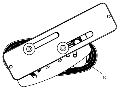
Referring to Figures 1-13, there is illustrated in various views, an
adjustable four plate assembly 10 for a chair 12 in accordance with the
preferred embodiment of the present invention. The adjustable four plate
assembly 10 includes a first plate 14, a second plate 16, third plate 18 and a
fourth plate 20.
The first plate 14 has a profile 22 having a top and a bottom surface 23
and 25 respectively and that includes at least three apertures 24, at least
two
sleeves 26 and two bosses 27. The two sleeves 26 and two bosses 27 are
located on the top surface 23, so that the bosses 27 extend beyond the top
surface 23 of the first plate 14. The apertures 24 are adapted to receive
various fastening means (not shown), for example, at least two of the
apertures 24 may be hexagonal in shape to receive two indented hex head
bolts. Furthermore at least one aperture 24 is centrally located in the first
plate 14. The sleeves 26 are adapted to each receive a spring and a bearing
ball (not shown). The first plate 14 may be made from acetal.
The second plate 16 has a profile 30 with both a top and a bottom
surface 32 and 34 respectively and includes at least two sleeves 36 on the top
surface 32. There is at least one sleeve 38 centrally located on the bottom
surface 34 of the second plate 16 and sleeve 38 is adapted to fit into
centrally
located aperture 24 of the first plate 14. The second plate 16 further
includes
at each end 40 of the second plate 16 a curved slot 41. The curved slots 41
each accommodate one of the bosses 27 when the first plate 14 and the
second plate 16 are aligned together. The curved slots 41 accommodate the
angular pivoting action or movement of the adjustable four plate assembly 10
explained herein below. The bottom surface 34 of the profile 30 of the second
plate 16 is adapted to fit the top surface 23 of the profile 22 of the first
plate
14. The second plate 16 may be made from coated steel.
CA 02425374 2004-12-20
-8-
The third plate 18 has a profile 42 with both a top and a bottom
surface, 44 and 46 respectively and includes at least two apertures 48 having
two sleeves 50 that extend beyond the top surface 44. The apertures 48 and
the sleeves 50 are adapted to receive various fastening means (not shown).
For example, the apertures 48 may be hexagonal in shape to receive two
indented hex head bolts. The bottom surface 46 further includes two sleeves
49 that are adapted to each receive a spring and a bearing ball (not shown).
The third plate 18 also includes two bosses 51 located on the top surface 44
of the third plate 18. The bosses accommodate the spring length and also act
as an additional stop for the forward-backward motion. The third plate 18
further includes a series of teeth 53 on the outside edge of the length of the
plate.
The third plate 18 further includes at each end 52 of the third plate 18,
an oblong slot 54 oriented across the width of the third plate 18. Each of the
oblong slots 54 accommodate the sleeves 36 when the second plate 16 and
the third plate 18 are aligned together. The oblong slots 54 accommodate the
sliding motion or movement from side to side (or lateral width) of the
adjustable four plate assembly 10 explained herein below. The bottom
surface 46 of the profile 42 of the third plate 18 is adapted to fit the top
surface 32 of the profile 30 of the second plate 16. The third plate 18 may be
made from acetal.
The fourth plate 20 has a profile 58 with both a top and a bottom
surface, 62 and 60 respectively. The top surface 62 is further defined as
having a wall 63 that runs around the edge of the top surface 62. The fourth
plate 20 includes at least two apertures 64 and an elongated recess 66 on the
bottom surface 60 of the fourth plate 20. The fourth plate 20 further includes
on each side, oblong slots 68 oriented along the length of the fourth plate
20.
Furthermore, the fourth plate 20 has a series of teeth 70 on the inside of the
wall 63 that engage with teeth 53 on the outside wall of the third plate 18.
CA 02425374 2008-01-28
-9-
The elongated recess 66 accommodates the two bosses 51 of the third
plate 18 and each of the oblong slots 68 accommodate the two sleeves 50 of
the third plate 18. The oblong slots 68 accommodate the sliding action or
movement forwards and backwards (or longitudinal depth) of the adjustable
four plate assembly 10 described herein below. The bottom surface 60 of the
fourth plate 20 is adapted to receive the top surface 44 of the profile 42 of
the
third plate 18. The fourth plate 20 may be made from glass-filled nylon.
The adjustable four plate assembly 10 may be assembled in the
following fashion by way of example only. The first plate 14 has two indented
hex head bolts inserted into the hex shaped apertures 24 from the top surface
23 of the first plate 14. Two springs may then be inserted into the two
circular
sleeves 26 in the first plate 14. One bearing ball may be placed on top of
each of the springs for a total of two balls. The bearing ball may be made of
chrome alloy steel.
The second plate 16 is then added to the first plate 14 so that the
bottom surface 34 of the profile 30 of the second plate 16 is aligned with the
top surface 23 of the profile 22 of the first plate 14. In this position, the
central
aperture 24 of the first plate 14 is aligned with the centrally located sleeve
38
on the bottom surface 34 of the second plate 16. In this position the
centrally
located sleeve 38 goes through the central aperture in the first plate 14.
Both the first and second plates 14 and 16 respectiveiy are then held
tightly together. A fastener, such as a truss head screw by way of example, is
then inserted through the centrally located sleeve 38 and tightened thereby
securing the first plate 14 and the second plate 16 together. Once the first
and second plates 14 and 16 respectively are assembled, this subassembly is
set aside.
The third plate 18 is positioned with the top surface 44 inverted and the
two bosses 51 pointing down. Two indented hex head bolts are inserted into
CA 02425374 2004-12-20
-10-
the hexagonal shaped apertures 48 from the bottom surface 46 of the third
plate 18 so that they extend beyond the sleeves 50 of the top surface 44 of
the third plate 18. Two springs are inserted into the two sleeves 49, followed
by a bearing ball on top of each of the springs. The bearing ball may be made
of chrome alloy steel. The subassembly of the first plate 14 and second plate
16 is then positioned over the third plate 18 so that the two sleeves 36 on
the
top surface 32 of the second plate 16 point downwards. The subassembly is
then placed on top of the third plate 18 so that the second plate 16 and the
third plate 18 are adjacent to each other. The two sleeves 36 of the second
plate 16 are therefore positioned into the two oblong slots 54 in the third
plate
18.
In this position both the second and third plates 16 and 18 are aligned
with one another and the third plate 18 is positioned in the middle of the
second plate 16. While compressing the first, second and third plates 14, 16,
and 18 together and engaging the springs, the assembly is then inverted so
that the top surface 44 of the third plate 18 is pointing upwards. A washer
(not shown) is placed on top of each of the sleeves 36 from the second plate
16 that protrude through the oblong slots 54. A fastener such as a truss head
screw is then inserted through the washer into each of the sleeves 36 and
each is tightened.
The fourth plate 20 is then placed on top of third plate 18 so that the
indented hex head bolt shafts from the third plate 18 come through the oblong
slots 68 of the fourth plate 20. A washer is then placed over each of the
indented hex head bolt shafts. A machine screw nut is placed onto each of
the hex head bolt shafts and tightened. Hardware is not shown.
The adjustable four plate assembly 10 may then be mounted by way of
example to a chair arm. The indented hex head bolts that were inserted into
the hex shaped apertures 24 of the first plate 14 may be used to mount the
adjustable four plate assembly 10 to an arm chair support and the apertures
CA 02425374 2004-12-20
-11-
64 in the fourth plate 20 may be used to attach an arm rest. The adjustable
four plate assembly 10 therefore allows for the adjustment of the individual
chair arms to a number of desired positions.
In operation, the adjustable four plate assembly 10 allows for the
movement of the second plate 16 in a pivoting action from side to side, the
movement of the third plate 18 in a sliding motion from side to side, and the
movement of the fourth plate 20 in a sliding motion forwards and backwards.
How this is achieved is explained herebelow with reference to Figures 14-21.
Figures 14 and 15 illustrate the four plate assembly 10 in the slide
forward position. In this position the user would have applied pressure in the
forward position so that the fourth plate 20 slides along the oblong slots 68
to
the desired position. Figure 16 illustrates the four plate assembly 10 in the
slide side to side position. In this position the user would have applied
pressure either to the outside or the inside of the arm rest so that the third
plate 18 slides along the oblong slots 54 oriented along the width of the
third
plate 18 to the desired position.
Figure 17 illustrates in a top view the four plate assembly 10 in the
pivoted position. In this position the user would have applied pressure either
to the left or the right allowing for the pivoting of the second plate 16
along the
curved slots 41 to the desired position.
Figures 18 and 19 in a top view and an end view illustrate the four plate
assembly 10 in both the slid forward position and the slid sideways position.
Figures 20 and 21 illustrate in a top view and an end view the four plate
assembly 10 adjusted in all three positions slide forward, slide side ways and
pivot.
The individual pivot positions are defined separately from the general
pivot motion by using a first series of slots 102 in the second plate 16 and
the
CA 02425374 2008-01-28
-12-
two spring and bearing ball assemblies in the first plate 14. When the second
plate 16 is placed on top of first plate 14, the second plate 16 compresses
the
spring and bearing ball assemblies. The series of slots 102 in the second
plate 16 define specific angular positions.
When the second plate 16 is rotated on the first plate 14, the bearing
ball is pushed down, compressing the spring, allowing second plate 16 to
move over top of the first plate 14. When the next slot 102 is reached, the
bearing ball can move upward and the spring can extend upward so that the
bearing ball engages the available slot. This motion can occur in either the
clock-wise or counter-clock-wise direction. The motion and positions are
controlled by extension and compression of springs and bearing balls into
slots 102.
The side to side movement or width adjustment is also controlled by a
second series of slots 110 in the second plate 16, springs, and bearing balls
(similar to the pivot motion) to define the width adjustment of the armrest.
In
the width adjustment motion, two springs are placed in the sleeves 49 in the
third plate 18. Two bearing balls are then placed on top of these two springs.
The second series of slots 110 are used to define the individual
positions for the width adjustment motion. The third plate 18 can be slid
across the top surface 32 of the second plate 16. When the third plate 18 is
moved, the sleeve 36 slides laterally in the oblong slot 54. The oblong slots
54 limit the amount of width adjustment available. Similarly, to the pivot
motion, the bearing balls are compressed, causing the springs to be
compressed, allowing the third plate 18 to pass over top. When the next slot
110 is reached, the ball can move upward, allowing the spring to extend, and
the ball to engage in the slot 110.
The spring properties are what define the amount of force required to
move the arm between the pivot positions. Because of this, it is possible to
CA 02425374 2004-12-20
-13-
use different springs with different properties to alter the force required to
move from angular position to angular position. By doing this, it is possible
to
adjust the feel of the motion for the desired application. Also, the pivot
motion
is independent of the other two motions, therefore the assembly can be
pivoted without having to change width or longitudinal positions.
The force required to move the plates is also a function of the
clearance between the plates. The more tightly together the plates are held,
the more force is required to move the arm to different positions. For the
pivot
and side-side motion, by holding the related plates very tightly together, the
springs can be pre-loaded (compressed initially), thus increasing the minimum
force required to move the arm in these directions. For the front-back motion,
if the hardware is tightened aggressively, the plastics can be compressed,
increasing the minimum force required to move the arm in this direction.
As described for the pivot motion, the spring is what determines the
force required to move from position to position. Because the width
movement has a separate series of position slots, separate springs, and
separate paths, the width motion can be adjusted for specific applications,
independently of the other two motions (pivot and depth). It can also be
achieved as a stand-alone motion, for example the assembly can be moved
laterally without pivoting or sliding forward or backward.
The adjustable four plate assembly 10 can be moved forward and
backward, but unlike the other two motions, this motion does not use a spring
and bearing ball combination to achieve individual positions. For depth
adjustment, the fourth plate 20 slides along the top surface 44 of the third
plate 18.
The material properties of third plate 18 and the fourth plate 20 allow
the walls of each plate to flex so that each set of teeth 53 and 70 can move
past one another into the next position (the third plate 18 is made of acetal
CA 02425374 2004-12-20
-14-
and the fourth plate is made of glass-filled nylon). These materials are
typically used in combination for wear applications. The amount of depth
adjustment available is determined by two oblong slots 68. The clearance
between the two sleeves 50 of the third plate 18 and the oblong slots 68 in
the
fourth plate 20 allow the sleeves 50 to slide freely in the oblong slots 68.
These two sleeves 50 ensure the motion is in one direction only and act as
stops at the end of the oblong slots. The individual positions are defined by
the teeth 53 on the third plate 18 and the teeth 70 of the fourth plate 20.
To adjust the force required to move the fourth plate 20 forward and
backward, the clearance between the teeth 53 and 70 can be altered. This
can be done by adjusting the sizing of the plates during the injection
moulding
process or through a change to the injection mould. Although this is not as
simple as changing a spring for the other motions, the force required for
depth
motion can still be adjusted without affecting the other motions. The amount
of depth adjustment available can be changed by altering the length of the
oblong slots 68.
As illustrated in the Figures, the adjustable four plate assembly 10 can
accommodate a variety of positions according to the user's desire for
positioning the arm rest. These movements may be achieved in isolation, or
in a variety of combinations. For example, the user may wish to have the arm
rest forward and pivoted slightly inwards, or the user might wish to have the
arm rest slid away from the user's body to allow for easier and greater access
to the chair 12 itself. The adjustable four plate assembly 10 may also be
adapted and mounted at other locations on a chair 12 for example a chair
back or lumbar support.
Other variations and modifications of the invention are possible. All
such modifications or variations are believed to be within the sphere and
scope of the invention as defined by the claims appended hereto.