Note: Descriptions are shown in the official language in which they were submitted.
CA 02425517 2003-04-07
WO 02/063983 PCT/US02/01493
1
TOKEN DISPENSING GAME APPARATUS
FOR YOUNG CHILDREN
SPECIFICATION
Field of the Invention
This invention relates generally to token
dispensing game apparatus and particularly to such
apparatus designed to meet the specific needs of very
young children.
Background of the Invention
The challenge of creating and producing games
which are appropriate for play by young children such
as young children between the ages of three and four
years old represents a substantial endeavor. Games
for such very young children must be easy to
manipulate given the limited dexterity and manual
control of such young children. Further, such games
must be easy to understand and must develop play
patters which can be readily comprehended by young
children. Furthermore, games intended for very young
children must, of necessity, be extremely to learn and
simple in their game results. In addition to these
requirements, such games must, of necessity be amusing
and interesting to engage the interest of young
children. Generally this requirement of interest and
amusement is met by providing games which are highly
centered on attention grabbing action features.
CA 02425517 2003-04-07
WO 02/063983 PCT/US02/01493
2
In addition, practitioner's in the art are often
endeavoring to provide games for young children which
enhance skill development and learning. For the most
part, such skill enhancement must be limited to
relatively basic skills such as hand/eye coordination,
color discrimination, shape and geometric
relationships, numbers or quantities as well as the
concept of sequence or sequential actions. It is well
recognized among practitioner's of the toy arts that a
particular game or toy may succeed or fail based upon
its attraction to the child user. However, commercial
success often results from skill development qualities
in a toy or game appreciated by the parents of such
children.
Faced with such challenges and somewhat
conflicting requirements and motivated by desires for
producing successful games, practitioner's in the toy
and game art have provided a virtually endless variety
of games directed toward very young children. For
example, U.S. Patent 5,480,150 issued to Weyand sets
forth a SYSTEM FOR GENERATING RANDOM OUTCOMES USING
DISC'S in which a plurality of discs bearing markings
or other indicators differentiate them one from
another are used to randomly select a number of
possible outcomes. The discs may be used to introduce
an element of chance in games. Each disc has two
sides, one of which is marked with a number. The
discs are grouped into sets and the number marked on
each disc in a set is the same within the set but is
different from all other discs. To use the discs to
randomly select an outcome, a persons stacks all of
the discs on top of one another and upsets the stack.
CA 02425517 2003-04-07
WO 02/063983 PCT/US02/01493
3
U.S. Patent 5,662,325 issued to Weyand sets forth
a SYSTEM FOR GENERATING RANDOM OUTCOMES USING DISCS
which is a continuation in part of U.S. Patent
5,480,150 adding alternative numeric indicators to the
discs.
U.S. Patent 5,634,639 issued to Tokito et al.
sets forth a BALL GAME APPARATUS WITH A PLURALITY OF
DIFFERENT BALLS AND WINNING POCKET PORTIONS in which a
game apparatus includes a spiral rail for
automatically delivering balls together with a field
portion on which the delivered balls are able to roll
with a degree of freedom. Winning pocket portions and
invalid pockets are formed in the field portion for
receiving a plurality of balls therein. A CCD camera
is provided for counting the number of balls received
in the winning pocket portion.
U.S. Patent 3,845,958 issued to Weinertsen sets
forth a LETTERS AND NUMBERS GAME for teaching children
basic letters and number concepts. A plurality of
character discs having distinct characters, letters or
numbers formed thereon cooperate with complementary
characters or the like formed on character trays
within the toy. In addition, a device is provided
which includes a housing having disc storage and
dispensing stations therein. A ramp at the storage
station is provided for supporting a plurality of
individual character discs in an aligned stack while a
pusher is provided to urge the discs toward the
dispensing station. A dispensing plate is mounted for
reciprocal movement at the dispensing station for
removing individual discs and discharging them from
the toys housing.
CA 02425517 2003-04-07
WO 02/063983 PCT/US02/01493
4
U.S. Patent 936,057 issued to Taylor; U.S. Patent
1,655,296 issued to Tapio; U.S. Patent 2,731,268
issued to Raizen; and U.S. Patent 2,721,083 issued to
Allain set forth examples of early token and ball type
chance games.
U.S. Patent 2,893,735 issued to Tranter Jr.; U.S.
Patent 3,048,402 issued to Schaper; and U.S. Patent
3,437,338 issued to Glass et al. set forth further
early examples of random chance games using objects
such as balls or tokens.
U.S. Patent 5,118,114 issued to Tucci set forth a
METHOD AND APPARATUS FOR PLAYING A POKER TYPE GAME
which includes a betting table, a random selection
device for selecting the dealer's spot or hand or
playing cards. The betting table is arranged in a
system facilitating the betting rules of a new game
known as Action Poker which automatically permits a
player to know their status from an odd or no-pay
stand point after each card.
U.S. Patent 2,792,227 issued to Auerbach; U.S.
Patent 2,003,979 issued to Skoric; and U.S. Patent
2,705,900 set forth examples of early random selection
apparatus of the type used in various games.
In a related art, U.S. Patent 2,759,632 issued to
Ussery et al. and U.S. Patent 2,979,230 issued to
Calverly set forth examples of tablet or pill
dispensing apparatus.
CA 02425517 2003-04-07
WO 02/063983 PCT/US02/01493
While the foregoing prior art devices have to
some extent improved the art and have in some
instances enjoyed commercial success, there remains
nonetheless a continuing need in the art for evermore
5 improved, interesting and amusing game apparatus for
young children.
Summary of the Invention
Accordingly, it is a general object of the
present invention to provide an improved game
apparatus. It is a more particular object of the
present invention to provide an improved game
apparatus which is particularly suited to the needs of
very young children. It is a still more particular
object of the present invention to provide an improved
game apparatus suited to the needs of young children
which aides such young children in the development of
a number of basic skills such as hand/eye
coordination, color discrimination, shape and
geometric relationships, numeric quantities and
sequence of activities.
In accordance with the present invention there is
provided a game apparatus comprising: a figure having
a head defining a slot, a torso, a moveable arm and a
torso support; a plurality of tokens received within
the head through the slot; a rotatable plate within
the head; gear drive means, coupled between the
moveable arm and the rotating plate, for rotating the
plate in response movement of the moveable arm; and a
token gate supported within the figure operative in
response to movement of the gear drive means to allow
a token to move from the figure, the moveable arm
CA 02425517 2003-04-07
WO 02/063983 PCT/US02/01493
6
being moved by a game player to rotate the rotating
plate and agitating the plurality of tokens and the
gear drive means and the token gate cooperating to
dispense a token from the figure.
Brief Description of the Drawings
The features of the present invention, which are
believed to be novel, are set forth with particularity
in the appended claims. The invention, together with
further objects and advantages thereof, may best be
understood by reference to the following description
taken in conjunction with the accompanying drawings,
in the several figures of which like reference
numerals identify like elements and in which:
Figure 1 sets forth a front view of a token
dispensing game apparatus constructed in accordance
with the present invention;
Figure 2 sets forth a partial section side
elevation view of the present invention token
dispensing game apparatus;
Figure 3 sets forth a partial section view of the
present invention token dispensing game taken along
section lines 3-3 in Figure 2;
Figure 4 sets forth a partial section view of the
present invention token dispensing game apparatus
taken along section lines 4-4 in Figure 2;
Figure 5 sets forth a partial section view of the
present invention game apparatus corresponding to the
CA 02425517 2003-04-07
WO 02/063983 PCT/US02/01493
7
section view of Figure 4 showing the completion of an
operative cycle of the game mechanism.
Description of the Preferred Embodiment
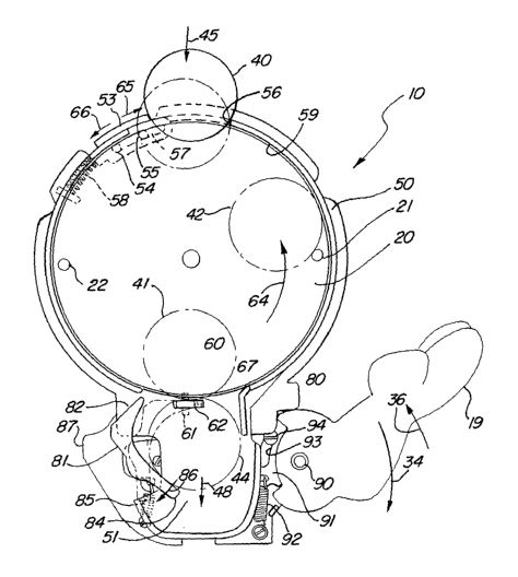
Figure 1 sets forth a partial sectioned front
view of a game apparatus constructed in accordance
with the present invention and generally referenced by
numeral 10. Game apparatus 10 is fabricated to
generally resemble a fanciful cartoon figure however,
it will be understood by those skilled in the art that
game apparatus 10 may be fabricated to present other
appearances without departing from the spirit and
scope of the present invention. Game apparatus l0
includes a body 11 preferably formed of a molded
plastic material or the like having a head 12
supporting a clear face plate 14 having a fanciful
partial face image thereon. Head 12 further supports
a cap 17 defining a slot 13 in the upper portion
thereof. Head 12 further includes a front plate 18
and a rotating plate 20. As is better seen in Figure
2, front plate 18 is positioned in front of a back
plate 50 to define an interior cavity 15 therebetween.
Rotating plate 20 includes a pair of cylindrical pegs
21 and 22 and is rotatably supported within interior
cavity 15. Body 11 further includes a torso portion
16 supported by a generally cylindrical stand 31 upon
a support base 30. Torso 16 further supports a door
32 having an upper hinge 33 allowing door 32 to pivot
outwardly from the bottom in the manner illustrated in
Figure 2. Body 11 further includes an arm 19 which is
pivotally supported in the manner set forth below in
Figure 3. Suffice it to note here, that arm 19 is
CA 02425517 2003-04-07
WO 02/063983 PCT/US02/01493
8
capable of being pivoted downwardly in the direction
indicated by arrow 34.
In further accordance with the present invention,
a plurality of generally disc-shaped tokens 40, 41,
42, 43 and 44 are utilized in playing the intended
game of the present invention game apparatus.
Accordingly, tokens such as token 40 are inserted
through slot 13 into interior cavity 15. Within
interior cavity 15, a plurality of tokens such as
tokens 41, 42 and 43 are captivated and visible behind
clear face plate 14 and clear front plate 18. While
front plate 18 and face plate 14 are preferably
fabricated of a transparent clear plastic material, it
will be apparent to those skilled in the art that
tinted or colored transparent materials may be used
without departing from the spirit and scope of the
present invention.
In operation, the child user inserts a plurality
of tokens through slot 13 to be received within
interior cavity 15. The tokens deposited through slot
13 are visible through clear face plate 14 and clear
front plate 18. The child then pivots arm 19
downwardly in the direction indicated by arrow 34. By
means set forth below in greater detail, the downward
movement of arm 19 imparts a rotation to rotating
plate 20 in the direction indicated by arrow 46. The
rotation of rotating plate 20 causes pegs 21 and 22 to
impact and move tokens within interior cavity 15 such
as tokens 41, 42 and 43. As rotating plate 20
continues to spin, the tokens within interior cavity
15 are rapidly moved and irrationally tumbled. By
means set forth below in greater detail, the mechanism
CA 02425517 2003-04-07
WO 02/063983 PCT/US02/01493
9
operative within torso 16 also operates to allow a
single one of the tokens rotating and spinning within
interior cavity 15 to be dispensed downwardly through
torso 16 and outwardly passed door 32. The mechanism
which provides this action is set forth below and
described in greater detail. However, suffice it to
note here that a token gate 60 (seen in Figure 2)
together with an escapement 81 (seen in Figure 3)
cooperate under the impetus of arm 19 movement to
randomly permit a single token to be discharged
downwardly through torso 16 and door 32. The token
discharged is randomly selected which imparts an
element of chance and excitement to the intended game.
While a variety of game play scenarios may be
utilized in combination with game apparatus 10, one
popular game scenario involves using tokens of
different colors which player attempt to accumulate by
taking their respective turns in-moving arm 19. In
such a game scenario for example, players would be
called upon to be the first to accumulate a
predetermined combination of colors such as all colors
being different or all colors being the same. The
random chance by which tokens drop through slot 13
eventually are discharged through door 32 permits the
young child to enjoy a substantial excitement in the
game play.
Figure 2 sets forth a partial section view of the
present invention game play apparatus. As described
above, game play apparatus 10 includes a body 11
having a head 12 which in turn supports a cap 17
defining a slot 13 therein. Cap 17 is pivotally
supported upon head 12 by a hinge 24. Head 12 further
CA 02425517 2003-04-07
WO 02/063983 PCT/US02/01493
includes a clear or transparent face plate 14 together
with a clear or transparent front plate 18 and a back
plate 50. Back plate 50 may be fabricated of opaque
or clear material as the user chooses. A rotating
5 plate 20 having a peg 21 extending therefrom is
rotatably supported upon back plate 50 in the manner
shown in Figure 3. Rotating plate 20 is positioned
within interior cavity 15 formed between front plate
18 and back plate 50. A slot 25 is formed between
10 front plate 18 and back plate 50 in general alignment
with slot 13 of cap 17 to facilitate the gravity
driven insertion of a token such as token 40 being
dropped in the direction indicated by arrow 45.
The lower end portions of back plate 50 and front
plate 18 are generally forwardly curved to define a
passage 51 therebetween. The end of passage 51
defines an aperture 52 which is covered by a pivotally
secured door 32. Door 32 is hinged at its upper
portion at a conventional hinge 33. Torso 16 is
supported upon stand 31 which in turn is supported by
base 30.
In the preferred fabrication of the present
invention, a token gate generally referenced by
numeral 60 is positioned above passage 51 within
interior cavity 15. Token gate 60 includes a pivoting
support pin 61, an outer end 62 and a rearward end 68.
Pivot pin 61 supports token gate 60 in a pivoting
support which allows token gate 60 to move between the
closed position shown in Figure 2 and the open
position shown in Figure 3. A spring 63 is coupled to
token gate 60 urging token gate 60 toward the position
of closure shown in Figure 2. In the closed position
CA 02425517 2003-04-07
WO 02/063983 PCT/US02/01493
11
shown in Figure 2, token gate 60 prevents tokens
within interior cavity 15 from entering passage 51.
Conversely, in its open position, token gate 60 allows
a token within interior cavity 15 to enter passage 51
for ultimate discharge through aperture 52 and door
32. By means set forth below in Figures 4 and 5, a
gear segment 70 is moveable against end 68 of token
gate 60 as arm 19 (seen in Figure 4) is pivoted
downwardly. As is also described below in greater
detail, the movement of gear segment 70 in response to
movement of arm 19 causes token gate 60 to be pivoted
about pin 61 against the force of spring 63 to its
open position thereby allowing one token to fall
downwardly from interior cavity 15 to passage 51.
Figure 3 sets forth a partial section view of
game apparatus 10 taken along section lines 3-3 in
Figure 2. Game apparatus 10 includes a back plate 50
supporting a rotating plate 20. Back plate 50 further
defines a generally cylindrical wall 59 encircling the
outer edge of rotating plate 20. Wall 59 defines a
slot 56 in the upper portion thereof. Slot 56 is
substantially greater than the diameter of a token 45.
This allows token 45 to be dropped downwardly in the
direction indicated by arrow 45 through slot 56 and
into interior cavity 15 (seen in Figure 2). Game
apparatus 10 further includes a slidably supported
shutter 53 which defines a slot 57 therein. Slot 57
receives a pair of fasteners 54. The cooperation of
slot 57 and fasteners 54 allows shutter 53 to be
moveable in the directions indicated by arrows 65 and
66 to provide closure and opening respectively of slot
56. A spring 58 is supported upon back plate 50 and
is coupled to shutter 53 urging shutter 53 toward the
CA 02425517 2003-04-07
WO 02/063983 PCT/US02/01493
12
direction indicated by arrow 65. Thus, in the absence
of a token such as token such as token 40 being
inserted into slot 56, shutter 53 remains in its
extended position partially blocking slot 56 and
preventing the exit of any tokens within interior
cavity 15 (seen in Figure 2).
A gear plate 87 is joined to the lower edge of
back plate 50 and supports a guide 80. Gear plate 87
further supports a pivot 90 upon which arm 19 is
pivotally supported for movement in the directions
indicated by arrows 34 and 36. Arm 19 includes a gear
segment 91 moveable in conjunction with arm 19 and
defining slot 93. A fastener 94 is received within
slot 93 and secured to gear plate 87. A spring 92 is
coupled between gear plate 87 and gear segment 91 to
urge arm 19 upwardly in the direction indicated by
arrow 36. The cooperation of fastener 94 and the
upper end of slot 93 provides an upward travel limit
to maintain the raised position of arm 19 at the
position shown in Figure 3.
Game apparatus 10 further includes a token gate
60 supported within a slot 67 formed in back plate 50
by a pivot pin 61. As mentioned above, token gate 60
operates to prevent tokens within interior cavity 15
(seen in Figure 1) from moving downwardly from
interior cavity 15. As is also mentioned above, token
gate 60 is pivoted from the closed position shown in
Figure 2 to the open position shown in Figure 3 by the
action of a gear segment 70 (seen in Figure 2).
Game apparatus 10 further includes an escapement
mechanism 81 pivotally supported upon back plate 50 by
CA 02425517 2003-04-07
WO 02/063983 PCT/US02/01493
13
a pivot 83. Escapement 81 includes a spring 85, a
tooth 82 and a lower end 84. Spring 85 urges
escapement 81 toward the position shown in solid line
representation in Figure 3. By means set forth below
in Figures 4 and 5, escapement 81 is pivoted against
the force of spring 85 in the direction indicated by
arrow 86 as arm 19 is pulled downwardly in the
direction indicated by arrow 34. By means also set
forth below in greater detail, the downward movement
of arm 19 causes rotating plate 20 to be spun in the
direction indicated by arrow 64.
As arm 19 is pivoted downwardly in the direction
indicated by arrow 34, gear segment 70 (seen in Figure
4) pivots token gate 60 to its open position. This in
turn allows a single token such as token 41 to move
downwardly passed guide 80 and escapement 81 to the
position occupied by token 44 in Figure 3. By means
also set forth below in greater detail in Figures 4
and 5, the completion of a downward stroke of arm 19
pivots escapement 81 to the dash line position shown.
This pivotal movement of escapement 81 prevents
further token passage from interior cavity 15 (seen in
Figure 2). Thus, in this manner, a single token
randomly aligned with token gate 60 is passed beyond
token gate 60 downwardly into passage 51 (seen in
Figure 2) to the position shown by dashed line token
44.
As arm 19 continues to move downwardly, and as
escapement 81 continues to pivot toward the dashed
line position shown, end portion 84 of escapement 81
pivots in the.directions indicated by arrow 86. At
some point, the pivotal movement of end 84 is
CA 02425517 2003-04-07
WO 02/063983 PCT/US02/01493
14
Buff icient to release token 44 allowing it to fall
downwardly in the direction indicated by arrow 48.
With temporary return to Figure 2, it will be apparent
that the downward drop of a token such as token 44
through passage 51 and aperture 52 will pivot door 32
in the direction indicated by arrow 35 allowing the
token to be ejected from the game apparatus.
In this manner, the selection of a given token
for release from head 12 of game apparatus 10 and
discharge through door 32 is entirely a matter of
random chance. This improves the excitement of the
games played with the apparatus and is compatible with
very young children where a minimum skill level is
available.
Once arm 19 is released, spring 92 pivots arm 19
upwardly in the direction indicated by arrow 36. By
means set forth below in greater detail, the upward
movement of arm 19 moves gear segment 70 (seen in
Figure 2) away from token gate 60 and allows token
gate 60 to again assume its closed position.
Concurrently, the upward pivotal movement of arm 19
returns escapement 81 to the solid line position shown
under the force of spring 85.
Figures 4 and 5 set forth identical section views
of game apparatus 10 both of which are taken along
section lines 4-4 in Figure 2. However, by way of
overview, it will be noted that Figure 4 shows a
section view of game apparatus 10 having arm 19 in its
raised position while Figure 5 sets forth the same
section view having the game apparatus in the
CA 02425517 2003-04-07
WO 02/063983 PCT/US02/01493
configuration and position resulting from downward
pivotal movement of arm 19.
More specifically, game apparatus 10 includes a
5 gear plate 87 supporting a pivot 90 which in turn
pivotally supports an arm 19. Arm 19 is joined to a
gear segment 91 having a slot 93 formed therein. A
fastener 94 is received within slot 93 and provides an
upward travel limit stop for arm 19. A spring 92 is
10 coupled between gear plate 87 and gear segment 91 to
urge arm 19 toward its fully raised position.
Gear 101 is rotatably supported upon a pivot 100
and defines a slot 103 therein. A limit stop 104
15 extends into slot 103 from gear plate 87 and limits
the travel of gear 101. Gear 101 further supports a
gear segment 70 all of which is rotatable about a pin
100. An arcuate guide 110 is positioned against gear
segment 70 to provide a bearing surface for movement
thereof.
An escapement 81 includes a pivot 83 and a cam
105. Escapement 81 further includes a tooth 82 and a
lower end 84. A spring 85 urges escapement 81 and cam
105 toward a counter-clockwise rotation about pivot
83. A post 102 is supported upon gear 101 and
interacts with cam 105 to move escapement 81.
A shaft 117 rotatably supports rotating plate 20
(seen in Figure 3) and a gear 118. Gear 118 is joined
to and rotatable with rotating plate 20 (seen in
Figure 3). A shaft 111 supports a gear 112 which in
turn is coupled to a ratchet mechanism 113. Ratchet
mechanism 113 includes an inner portion joined to gear
CA 02425517 2003-04-07
WO 02/063983 PCT/US02/01493
16
112 and an outer portion joined to gear 116. Gear 116
engages gear 118.
In the position shown in Figure 4, arm 19 is its
relaxed or raised position and is maintained in the
raised position by the force of spring 92. Also in
the position shown in Figure 4, gear segment 70 is
pivoted away from token gate 60 (seen in Figures 2 and
3) allowing token gate 60 to maintain its closed
position. The operative cycle of the present
invention game apparatus is initiated as the user
pushes arm 19 downwardly about pivot 90 in the
direction indicated by arrow 120. The resulting
movement of arm 19 and gear segment 91 produces the
sequences of movements shown in Figure 5.
By way of overview, Figure 5 shows the resulting
positions of components within game apparatus 10 as
arm 19 is pivoted downwardly about pivot 90 to the
full downward travel limit.
More specifically, game apparatus 10 includes a
gear plate 87 supporting a pivot 90 which in turn
pivotally supports an arm 19. Arm 19 is joined to a
gear segment 91 having a slot 93 formed therein. A
fastener 94 is received within slot 93 and provides an
upward travel limit stop for arm 19. A spring 92 is
coupled between gear plate 87 and gear segment 91 to
urge arm 19 toward its fully raised position.
Gear 101 is rotatably supported upon a pivot 100
and defines a slot 103 therein. A limit stop 104
extends into slot 103 from gear plate 87 and limits
the travel of gear 101. Gear 101 further supports a
CA 02425517 2003-04-07
WO 02/063983 PCT/US02/01493
17
gear segment 70 all of which is rotatable about a pin
100. An arcuate guide 110 is positioned against gear
segment 70 to provide a bearing surface for movement
thereof.
An escapement 81 includes a pivot 83 and a cam
105. Escapement 81 further includes a tooth 82 and a
lower end 84. A spring 85 urges escapement 81 and cam
105 toward a counter-clockwise rotation about pivot
83. A post 102 is supported upon gear 101 and
interacts with cam 105 to move escapement 81.
A shaft 117 rotatably supports rotating plate 20
(seen in Figure 3) and a gear 118. Gear 118 is joined
to and rotatable with rotating plate 20 (seen in
Figure 3). A shaft 111 supports a gear 112 which in
turn is coupled to a ratchet mechanism 113. Ratchet
mechanism 113 includes an inner portion joined to gear
112 and an outer portion joined to gear 116. Gear 116
engages gear 118.
As arm 19 is pivoted downwardly in the direction
indicated by arrow 120 overcoming the force of spring
92, gear segment 91 is pivoted upwardly in the
direction indicated by arrow 121. The engagement of
gear segment 91 and gear 101 rotates gear 101 about
pin 100 in the direction indicated by arrow 122. The
extent of rotation of gear 101 is limited by the
action of limit stop 104 against the end of slot 103.
As gear 101 pivots in the direction indicated by
arrow 122, gear segment 70 pivots in the direction
indicated by arrow 123 engaging gear 112.
Concurrently, the pivoting of gear 101 in the
CA 02425517 2003-04-07
WO 02/063983 PCT/US02/01493
18
direction of arrow 122 forces post 102 against cam
105. As post 102 moves against cam 105, escapement 81
is pivoted in the direction indicated by arrow 124.
This pivotal movement of escapement 81 moves tooth 82
inwardly in the direction indicated by arrow 125.
It will be recalled that gear segment 70 operates
as it is pivoted in the direction indicated by arrow
123 to move token gate 60 (seen in Figures 2 and 3)
from its normally closed position to its open
position. Thus, a period of time exists during which
token gate 60 (seen in Figures 2 and 3) is moved to
its open position and escapement 81 is in the process
of being pivoted in the direction indicated by arrow
124 by post 102 against cam 105. During this time
interval, tooth 82 has not yet moved into the blocking
position shown in Figure 5 and accordingly upon the
opening of token gate 60 (seen in Figures 2 and 3) a
single token descends downwardly passed token gate 60
in the position shown by token 44 in Figure 3.
Thereafter, as gear segment 70 continues to move in
the direction indicated by arrow 123 and tooth 182 of
escapement 81 moves in the direction indicated by
arrow 125 further dropping of any other tokens within
the game unit is prevented by the inward movement of
tooth 82. In this manner, the present invention game
apparatus operates to dispense a single token during a
downward stroke of arm 19.
As gear segment 70 moves in the direction
indicated by arrow 123, engaging gear 112 and rotating
it in the direction indicated by arrow 126, ratchet
113 engages gear 116 causing it to rotate gear 118 in
the direction indicated by arrow 127. As mentioned
CA 02425517 2003-04-07
WO 02/063983 PCT/US02/01493
19
above, the rotation of gear 127 produces a
corresponding rotation of rotating plate 20 (seen in
Figure 3). As rotating plate 20 spins in the manner
shown in Figure 1, the plurality of tokens within the
game unit are agitated and spun about for an amusing
effect.
Once the token has been dispensed and the
spinning of rotating plate 20 (seen in Figure 3) has
slowed or terminated, the user may release arm 19
allowing spring 92 to pivot arm 19 upwardly about
pivot 90 in the direction indicated by arrow 130.
This movement of arm 19 pivots gear segment 91 in the
direction indicated by arrow 131 which in turn rotates
gear 101 about pin 100 in the direction indicated by .
arrow 132. The pivoting movement of gear 101 in the
direction of arrow 132 pivots gear segment 70 in the
direction indicated by arrow 133. This in turn
rotates gear 112 in the direction indicated by arrow
136. In this reverse direction of rotation, the
engagement between gear 112 and gear 116 provided by
ratchet 113 is released and no corresponding rotation
of gear 116 or gear 118 taken place. Accordingly,
rotating plate 20 (seen in Figure 3) is not rotated in
a reverse direction as arm 19 is raised.
The pivotal movement of gear segment 70 in the
direction of arrow 133 does however return token gate
60 (seen in Figure 3) to its closed position. Thus
further token dispensing is prevented. As gear 101
rotates in the direction indicated by arrow 132, Post
102 moves away from cam 105 allowing spring 85 to
pivot escapement 81 about pivot 83 in the direction
indicated by arrow 134. This pivotal movement of
CA 02425517 2003-04-07
WO 02/063983 PCT/US02/01493
escapement 81 moves tooth 82 outwardly in the
direction indicated by arrow 135. At this point, the
mechanism has returned to the relaxed position shown
in Figure 4 in preparation for another cycle of
5 operation.
This token dispensing operation is repeated by
successive players and is maintained so long as the
supply of tokens within the game unit replenished.
While particular embodiments of the invention
have been shown and described, it will be obvious to
those skilled in the art that changes and
modifications may be made without departing from the
invention in its broader aspects. Therefore, the aim
in the appended claims is to cover all such changes
and modifications as fall within the true spirit and
scope of the invention.