Note: Descriptions are shown in the official language in which they were submitted.
CA 02425920 2003-04-16
BEhT FEED APPARATUS FOR
CONTINUOUS EXPANDED GRAPHITE; WEB
5
Field of the Invention
[0001 The present invention relates to web
handling apparatus, in particular, to belt feed
apparatus for feeding webs of expanded graphite
10 to downstream processing components.
Back round of the Invention
[0002 Electrochemical cells, such as fuel
cells, are typically employed in a stack wherein
15 multiple cells are connected together in series
and/or in parallel. Each cell in the stack is
typically disposed between two plates to form a
cell assembly. The plates act as current
collectors and provide support for the adjacent
20 electrodes. A plate can be shared between two
adjacent cell assemblies, in which case the plate
also serves as a separator to fluidly isolate
adjacent cell assemblies.
[0003 In .fuel cell assemblies, for instance,
25 plates known as flow field plates have open-faced
channels formed in one or both opposing major
surfaces for directing reactants and/or coolant
fluids to specific portions of such major
surfaces. The open-f aced channels also provide
30 passages for the removal of reaction products,
depleted reactant streams, and/or heated coolant
streams. For an illustration of a fluid flow
CA 02425920 2003-04-16
,. 2
field plate, see, for example, U.S. Patent No.
4,988,583, issued January 29, 1991.
[0004] Flow field plates can be made from an
electrically conductive, substantially fluid
5 impermeable material that is sufficiently
compressible or moldable so as to permit
embossing. Expanded graphite sheet is generally
suitable for this purpose because it is
relatively impervious to typical fuel cell
10 reactants and coolants and thus is capable of
fluidly isolating the fuel, oxidant, and coolant
fluid streams from each other; it is also
compressible and embossing processes can be
employed to form channels in one or both major
15 surfaces . 7E'o,r example, U. S . Patent No .
5,527,363, issued June 18, 1996, describes flow
field plates comprising a metal foil or sheet
interposed between two expanded graphite sheets
having flow c3kaannels embossed on a major surface
20 thereof.
[0005] Flow field plates can be manufactured
in volume by embossing a continuous web of
expanded graphite. Suitable methods and
apparatus for roller embossing a continuous web
25 of expanded graphite to from such plates is
described in U.S. Patent Application Serial No.
09/039,701, published November 1.5, 2001.
Embossing flow field plates from a continuous web
of expanded graphite, however, poses some web
CA 02425920 2003-04-16
- 3 -
handling problems that do not normally arise with
other web materials.
[0006] Unlike most web materials employed in
continuous processes, expanded graphite has a
5 very low tensile strength. However, some form of
tension control is recommended. Uncontrolled
tension can cause centering problems during
embossing and/or result in web breaks due to high
tensile loads developed.
10 [0007] At the same time, expanded graphite is
also very soft, so the web can easily be crushed
and/or the surface can be easily damaged. In
addition, the embossing process can elongate the
plate, with the die causing varying tension in
15 the web due to the complex features of the flow
field plate. Without adequate tension control,
this can result in stretching or other damage to
embossed features in the plate. Because of these
material limitations, conventional tension
20 control equipment, such as multiple-roller
tensioners, braked feed spools and/or braked nip
rollers cannot be employed without damaging the
expanded graphito web.
[0008] It would be desirable to have a
25 tensioning and feeding system for supplying a
continuous expanded graphite web to an embosser
that provided an adequate degree of tension
control whale avoiding damage to the web.
CA 02425920 2003-04-16
Summary of the Invention
[0009] A belt feed apparatus is provided for
receiving and feeding a continuous web of
expanded graphite. In one embodiment the
5 apparatus comprises a frame, at least one pair of
belts connected to the frame for receiving the
web of expanded graphite therebetween, a first
drive motor operably connected to the first pair
of belts for driving same at a drive speed, a
10 controller for varying the drive speed, and a
first moveable pressure plate operably connected
to the frame and adapted. to contact a. portion of
the inner surface of the first belt for applying
a variable friction force to the web.
15 [0010] In another embodiment, the present belt
feed apparatus comprises at least one pair of
endless belts for receiving the web of expanded
graphite therebetween, a drive motor operably
connected to the first pair of belts for driving
20 the first pair of belts at a drive speed, a
controller for varying the drive speed, and a
first load means for varying a friction force
applied to the web by the first pair of belts.
25 Brief Description of the Drawings
[0011] In the drawings, identical reference
numbers identify similar elements or acts. The
sizes and relative positions of elements in the
drawings are nat necessarily drawn to scale. For
CA 02425920 2003-04-16
example, the shapes of various elements and
angles are not drawn to scale, and same of these
elements are arbitrarily enlarged and positioned
to improve drawing legibility. Further, the
5 particular shapes of the elements as drawn, are
not intended to convey particular information
regarding the actual shape of the particular
elements, and have been selected for ease of
recognition in the drawings.
10 [0012] FIG. 1 is a schematic illustration of
an embossing line employing an embodiment of the
present belt feed apparatus.
[0013] FIG. 2 is a schematic elevation view of
the belt feed apparatus of FIG. 1.
15 [001] FIG. 3 is a schematic top view of the
belt feed apparatus of FIG. 1.
Detailed Description of Preferred Embodiments)
[0015] In the following description, certain
20 specific details are set forth i:n order to
provide a thorough understanding of the various
embodiments of the present apparatus. However,
one skilled in the art will understand that the
present apparatus care be practiced without these
25 details. In other instances, well-known
structures associated with roller embossing
equipment, drive motors, control systems and the
like have not been shown or described in detail
CA 02425920 2003-04-16
to avoid unnecessarily obscuring' descriptions of
the embodiments of the present apparatus.
[0016] As used in this description and in the
appended clai~~ns , "expanded graphite web" and '°web
5 of expanded graphite" means web materials
comprising expanded graphite, including
composites thereof such as, for example, the
composite described in U.S. Patent No. 5,885,728,
issued March 23, 1999. The terms also include
10 laminates that include one or more layers
comprising expanded graphite.
[0017] The present belt feed apparatus
comprises a pair of endless belts directly
opposed to each other for receiving an expanded
15 graphite web :9~etween them. The ;pair of belts is
driven by a motor at a drive speed synchronized
to the line speed of a downstream processing
component, such as a roller embosser, for
example.
20 [0018] FIG. 1 is a schematic illustration of
an embossing line employing an embodiment of the
present belt feed apparatus. A web of expanded
graphite 2 is fed from spool 4 to belt feed
apparatus 10. felt feed apparatus ZO then feeds
25 Web 2 to roller embossers 50.
[0019] The embossing line of FIG. 1 can also
comprise other equipment, as desired. For
example, pre-calendaring rolls, car apparatus for
embossing under reduced pressure, such as those
CA 02425920 2003-04-16
described in the published '701 application,
mentioned above, can be employed. Also, slitting
and cutting equipment can be employed downstream
of the embossing rollers in the manuf aeture of
5 flow field plates. As a further example, a
station employing a laser beam partially obscured
by the end of the manufactured plate could be
employed to measure the length of the plates, by
the quantity of light blocked by the plate
10 end(s), as a dimensional quality check. Other
suitable equipment will be apparent to persons
skilled in the art.
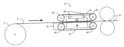
[0020 FIGS. 2 and 3 are further illustrations
(elevation and top views, respectively) of belt
15 feed apparatus 10. Guide 12 assists in feeding
web 2 to pairs of belts 14, 14' and 16, 16'. The
belts are driven around drive pulleys 18, 18' and
idler pulleys 20, 20' by motor 2;2. Drive pulleys
18, 18' are connected by common axles 24, 26,
20 respectively. Motor 22 is operatively connected
to axle 24 via sprockets 28, 30 and chain 32.
Motor 22 is also operatively connected to axle 26
via gears 34, 36. During operation, opposing
portions of the belts apply friction to web 2 and
25 feed it to embossing rollers 50. A controller
(not shown) controls motor 22 in order to vary
the drive speed of the belts and thus control the
line speed of the web as it is fed to embossing
rollers 50.
CA 02425920 2003-04-16
[0021] The pairs of belts in apparatus 10 can
be the same length or of clifferent lengths, and
can be directly opposed to each other, or offset
from each other, as desired.
5 [0022] Pistoxas 38 attached to frame 40 apply a
load to pressure plate 42. Pressure plate 42
contacts an inner portion of belts 14, 16,
applying a friction Force on web 2. Plate 44
supports a portion of belts 14', 16' and helps t~
10 ensure good contact between the belts and web 2.
The friction force applied to web 2 can be varied
by increasing the load exerted by pressure plate
42.
[0023] Instead of a single pressure plate 42,
15 individual pressure plates can be employed for
each pair of belts, if desired. Similarly,
individual support plates can be employed with
each pair of belts instead of single plate 44.
Pistons 38 can be mechanically, pneumatically or
20 hydraulically activated, and can be commonly or
independently controlled.
[0024] The gap between the pairs of belts can
be adjusted to accommodate expanded graphite webs
of different grades and/ar thickness, if desired.
25 For example, belts 14, 16 could be moveable
within frame 40 to vary the gap between the pairs
of belts. Of course, belts 14', 16' could
alternatively or additionally be moveable within
frame 40 for the same purpose.
CA 02425920 2003-04-16
_ g _
[0025] In the embodiment of FIGS. 1-3, two
pairs of belts are shown, with each pair of belts
configured to contact an edge portion of the
expanded graphite web. In applications where it
is desired to avoid contact with the belts in a
central portion of the web is to be embossed,
this configur tion can be employed. Generally
though, the number of pairs of belts employed is
not essential to the present apparatus. For
10 example, 1n other applications t'he web could be
notionally divided into a number of regions to be
embossed, eac:~ flanked by portio:r~s of the web
that are not: in such applications multiple pairs
of belts could be employed to co:ratact the web in
the unembossed portions. Alternatively, in
applications where contact between the belts and
the surface of the web does not adversely affect
the embossing process, one or mo:ge pairs of wider
belts could be employed.
[0026] Similarly, the number of drive motors
employed, and the means for operably connecting
them to the belts , are not essential to the
present apparatus.
[0027] The type and composition of the belts
is likewise not essential. to the present
apparatus , and persons o.f ardina:ry skill in the
art will be readily able to determine suitable
belts for a given application. Iaor example,
timing belts or flat belts can beg employed. The
CA 02425920 2003-04-16
- 10 -
belts should provide sufficient friction to move
the web; typically, belts with a substantially
flat Web-contacting surface can provide adequate
friction. In this context, a substantially flat
web-contacting surface includes flat, knurled,
checked and otherwise patterned belt surfaces
with sufficient flat surface area to provide
adequate contact with the web. Appropriate
surface materials include natural and synthetic
10 rubbers, and polymers such as urethane, nylon,
polyvinyl chloride (P~TC) and sila~cone .
[0028] During operation, the drive speed of
the present apparatus can be varied to match the
feed rate of downstream embossing equipment. The
15 degree to which the embossing process elongates
the embossed portion of the web depends on such
factors as the thickness and grade of expanded
graphite web employed and the pattern to be
embossed. This can also cause the effective line
20 speed of the web to be different from the drive
speed of the <embossing rollers . If the drive
speed of the belt feed apparatus and embossing
rollers are synchronized, as is 'typically the
case in conventional web handling systems, the
25 difference between the effective line speed of
tyre web and the drive speed of the embossing
rollers can result in excessive tension in the
web. To avoid damage to the web, therefore, the
drive speed of the present belt feed apparatus is
CA 02425920 2003-04-16
- 11 -
desirably controlled to substantially match the
line speed of the web, not the drive speed of the
embossing rollers.
[0029] Manual and/or automated controllers can
5 be employed with the present apparatus. The
particulars of the drive speed control system are
not essential to the present appars.tu,s; persons
skilled in the art can select suitable
conventional speed control systems for a given
application. For example, a two--axis servo
controller cowld receive input from a line
encoder and a speed trim potentiometer and
control the speed of the drive motor in response.
Alternatively, the speed or gearing of the motor
could be set manually.
[0030] While pistons are shown in FIGs. 1 and
2, the means .for applying a load to the belts are
not essential to the present apparatus, and
persons of ordinary skill in the art can select
20 suitable such means for a given <~,pplication. for
example, springs or expandable bladders
(pneumatic or hydraulic) can be employed ,in place
of the illustrated pistons. Alternatively,
expandable bladders could also b<_ employed to
directly contact the inner surface of the belts,
without the need for a pressure plate. Other
suitable load. means will be apparent to persons
skilled a.n the art. If desired, such means could
also be employed in place of plate 44 to apply a
CA 02425920 2003-04-16
- ~. 2 -
load to the inner surface of each of the pairs)
of opposed belts.
[0031] Although specific embodiments of and
examples for the belt feed apparatus are
5 described herein for illustrative purposes,
various equivalent modifications can be made
without departing from the scope of the invention
in light of the above-detailed description, as
will be recognized by those skilled in the
relevant art. In general, in the following
claims, the terms used should not be construed to
limit the invention to the specific embodiments
disclosed in the specification and claims, but
should be construed to generally include belt
feed systems :for expanded graphite Webs that
operate in accordance with the claims.
[0032] While particular steps, elements,
embodiments and applications of 'the present
invention have been shown and described, it will
20 be understood, of course, that the invention is
not limited thereto since modifications can be
made by persons skilled in the art, particularly
in light o~ the foregoing teachings . Tt is
therefore contemplated by the appended claims to
cover such modifications as incorporate those
steps or elements that come within the scope of
the invention.