Note: Descriptions are shown in the official language in which they were submitted.
CA 02426211 2003-04-18
21-12-2001 . DK000062~
P 415 FcQO ~ ° ~ ' ,
r
1 ,
Instrument for the parallel installation of dental implants
The. present invention relates to a dental device and a dental system that
functions
to assist in inserting implants in the jaw in particular in placing implants
parallel with
each other or parallel with a non-implant appliance supported in the mouth,
and to a
- method of installing implants in parallelism.
Background
Implants are now commonly used for providing anchor points in the jaw to which
supports are made far a single tooth, for multiple teeth, for bridges andlor
for .
4
prosthetic devices. If more than one implant is to be installed in the jaw or
if implants
are to be used in combination with existing non-implant appliances, it is
highly
desirable that all the implants be parallel with each other. This parallelism
makes for
precise and uniform angulation of implants in the jaw and also provides
precise
abutments in anchor teeth for bridges and the like. . - °
Several attempts have been made in the prior art for obtaining. a paralleling
device.
For example a device consisting of two arms, wherein one arm is attachable to
an
anchor means whereas the other arm is used to guide the burr for drilling the
necessary holes. The burr is typically led through a bore in the other arm. it
is
however difficult to obtain a precise parallel alignment with the anchor means
when
the burr is led through a bore in the arm since some tolerance is necessary
for the
burr to be able to perform the relevant drilling action. Furthermore, the
device
' requires that only burrs of a certain diameter are acceptable, namely those
fitting
into the bore of the arm.
US 5,302,122 discloses a dentistry implant paralleling device consisting of
several
identical shaped links capable of being pivotably connected for forming a
chain.
Furthermore, ons of the links may be connected to a dentist handpiece and
a'link at
the other end of the chain may be attached to an anchor means~in the jaw. By
the
use it is possible to drill a hole in the jaw paratlel to the anchor means. It
is however
. not possible to correct for the different height levels in the jawbone when
drilling.
Furthermore, due to the several links necessary to provide the relevant
movements
AMENDED SHEET
CA 02426211 2003-04-18
r . ._ . - , ~ DK00006~G
2 ~ -12-2001
P 415 PG00
some uncertainty with respect to the parallelism of the hotes~ remains, since
it is not
possible to design the releasable links without marginal tolerances. This is
also the
case in DE 37 30 055 describing an instrument for paralielly directing a
dentist's
burr. The instrument consists of three links, connected so that the links
cannot be
vertically moved in relation to each other during use of the instrument, and
in DE 19
60 394 describing an instrument for parallelly directing a dentist's burr. The
instrument consists of two telescopic anus connected through a cordon joint.
in
another reference, US 5,741,133, an instrument for paralleliy drilling holes
for dental
' implants, wherein the instrument has one arm, is described. This provides a
better
stability, but does also lead to an undesirably low mobility of the instrument
in use.
Summary of the irwention
The present invention relates to an apparatus for insertion of dental implants
in a
predetermined angle with respect to another implant, existing teeth or the
like. In
particular the invention relates to an apparatus for parallel insertion of
dental
implants comprising a paralleling apparatus and a denfal handpiece.
The invention will be described by reference to parallel insertion.
~0
In another embodiment the present invention relates to a system for parallel
insertion of dental Implants comprising a paralleling device and a dental hand
piece,
- wherein the paralleling device comprises at least a first arm and a second
arm, said
arms having a proximal end and a distal end, said first amp comprising means
for
pivotably connecting an anchor member thereby defining a first axis of
rotation, said
second arm comprising means for pivotably connecting attachment means of a
dental handpiece thereby defining a second axis of rotation, said arms being
pivatably connected by hinging means defiining a least a third axis of
rotation, said
first and second axes of rotation being substantially parallel,
wherein the dental handpiece further comprises means for securing a burr, the
attachment means and the burr securing means being so arranged that when the.
dental handpiece is pivotably connected to the second arm, the drilling axis
of the
burr is at a distance to the second arm and at a direction substantially
parallel to the
second axis of rotation, and .- --
AMENDEC7 SHEET
-__
r CA 02426211 2003-04-18
21-12-2001 ~ DI'f0~0062a
P 415 D1~01
- 2a . .
wherein the second arm andlor the attachment means of the dental handpiece .
comprises means for determining the level of position of the handpiece in
relation to
the second arm.
In another embodiment the present invention relates to a system for parallel
insertion of dental implants comprising a paralleling device and a dental
handpiece,
wherein the paralleling device comprises at least a first arrn and a second
arm, said
arms having a proximal end and a distal end, said first arm comprising means
for
pivotably connecting an anchor member thereby defcning a frrst axis of
rotation, said
AMENDED SHEET
CA 02426211 2003-04-17
WO 01/34055 PCT/DK00/00622
3
second arm comprising means for pivotably connecting attachment means of a
dental handpiece thereby defining a second axis of rotation, said arms being
pivotably connected by hinging means defining a least a third axis of
rotation, said
first and second axes of rotation being substantially parallel, wherein the
dental
handpiece further comprises means for securing a burr, the attachment means
and
the burr securing means being so arranged that when the dental handpiece is
pivotably connected to the second arm, the drilling axis of the burr is at a
distance to
the second arm and at a direction substantially parallel to the second axis of
rotation, and wherein the first arm and/or the anchor member comprises means
for
determining the level of position of the first arm in relation to the anchor
member.
In a further embodiment the present invention relates to an apparatus or
paralleling
device for parallel insertion of dental implants, said apparatus comprising:
at least a first arm and a second arm, said arms having a proximal end and a
distal
end, said first arm comprising means for pivotably connecting an anchor member
thereby defining a first axis of rotation, said second arm comprising means
for
pivotably connecting attachment means of a dental handpiece thereby defining a
second axis of rotation, said proximal ends of the first and second arms being
pivotably connected by hinging means defining a third axis of rotation, said
first,
second and third axes of rotation being substantially parallel,
wherein, for both the first and the second arms, the proximal end of an arm
has a
contact surface with the width of said contact surface being larger than the
height or
thickness of the proximal end of the corresponding arm, said hinging means
comprising an axle or shaft connecting the proximal ends with the two contact
surfaces laying flat up to each other in a supportive way.
In yet another embodiment the present invention relates to an apparatus or
paralleling device for parallel insertion of dental implants, said apparatus
comprising:
at least a first arm and a second arm, said arms having a proximal end and a
distal
end, said first arm comprising means for pivotably connecting an anchor member
thereby defining a first axis of rotation, said second arm comprising means
for
pivotably connecting attachment means of a dental handpieoe thereby defining a
second axis of rotation, said arms being pivotably connected by hinging means
defining a least a third axis of rotation, said first and second axes of
rotation being
substantially parallel,
SUBTITUTE SHEET (RULE 26)
CA 02426211 2003-04-17
WO 01/34055 PCT/DK00/00622
4
wherein the hinging means and/or at least one arm comprise fixation means for
locking two pivotably connected arms at a fixed angle.
When the instrument is adapted for being used for insertion in angles
different from
parallellity, at least one of the arms comprises means for receiving
attachment
means andlor anchor member at another angle than parallel with the third axis
of
rotation
By use of the present invention it is possible to drill holes for providing
parallel
anchor points in the jaw while at the same time securing that the system may
adjust
for the various height levels in the jaw. In the present context the term "non-
releasably, pivotably connected" is intended to mean that at least during the
drilling
performance the proximal ends of the two arms are secured in the same plane,
preferably the horizontal plane and cannot be disengaged.
Because the drilling axis does not pass any of the arms, the system may be
used in
connection with burrs of a wide variety of diameters.
A further object of the invention is a method for parallel insertion of a
dental implant
in a jaw bone comprising
establishing a first hole in the jaw bone,
arranging an anchor means in the hole,
using said anchor means as a pivot guide for an arm of a system as defined
above,
guiding a handpiece attached to the system said handpiece comprising a burr
for
drilling second holes) in the jaw bone that are parallel with the first hole,
and
inserting the implant.
Drawings
Fig. 1 is an exploded view of the system according to the invention.
SUBTITUTE SHEET (RULE 26)
CA 02426211 2003-04-17
WO 01/34055 PCT/DK00/00622
Fig. 2 is an elevated side view of the paralleling apparatus according to the
invention.
5 Fig. 3 is an elevated side view of the dental handpiece including a burr.
Fig. 4a and 4b shows a bush with a stopper mechanism and a bush without
stopper
mechanism, respectively.
Fig. 5 shows the system according to the invention during drilling a hole in
the jaw.
Fig. 6 is a plane view of the system of Fig. 5.
Fig. 7 shows an anchor member according to the invention.
Fig. 8 shows staircase formed distance piece according to the invention.
Detailed description of the invention
The invention is described in detail in relation to parallel insertion
apparatus.
When inserting implants in the jaw of an individual it is of importance to
secure that
the holes drilled in the jaw are parallel in order to provide parallel anchor
points for
the implants. Furthermore, it is of importance that it is possible to adjust
for the
various height levels in the jaw of the individual when drilling the holes.
The present
invention describes the solution to these problems which is described in
relation to
the system and the individual parts of the system for parallel insertion of
dental
implants is described in greater details, as well as the method for using the
system.
A major part of the system is a paralleling apparatus comprising at least two
arms, a
first arm and a second arm pivotably connected through a hinging means whereby
the arms may rotate in relation to each other. The first arm and the second
arm are
preferably of an elongated form having increased width in the proximal end for
forming the hinging means. The two arms have substantially identical
dimensions.
The arms may appear as straight arms or may be curved. Furthermore, the arms
SUBTITUTE SHEET (RULE 26)
CA 02426211 2003-04-18
21-12-2001 . ~i~C000062a
p 415 DK01
6
t may be provided with one or more recesses for allowing the burr an increased
radius of action and/or for decreasing the weight of the apparatus.
in a preferred embodiment the proximal end-of each arm is formed as an
essential
circufar extension of the arm provided with a bore through.which.a pin of the
hinging
means may be. inserted.
The first arm comprises means for pivotably connecting said arm to an anchor
member which anchor member is secured in the jaw of the individual to be
treated.
9 Q Thereby the anchor means serves as a pivot guide foe the first arm. in a
preferred
embodiment the means for pivotably connecting the anchor means is a bore in
the
distal end of the first arm. More preferred the means is a .bore through the
arm, said
bore being dimensioned to.receive the anchor means without leaving any
tolerances
that would otherwise disturb the ability of securing parallel holes.
. .
The anchor means of the jaw may be any suitable means normally used when
inserting implarits, such as a first burr also called the pilot burr, said
first burr being
used solely for drilling .a pilot hole in the jaw bone. The pilot hole is used
for securing
the parallelism of all. the other holes to be used for the implants. In
another
embodiment the anchor means is an anchor pin inserted into the pilot hole. The
dimensions of a pilot burr are often from 2 to 3 mm in diameter, mostly about
2.35
mm.
The anchor means may also be a hinge or a cap on one or more teeth, whereby it
is
possible to obtain paralleility with existing teeth.
In order to adjust for the various height levels in the jawbone, a bush is
preferably
incorporated in the bore of the distal end of the first arm for receiving the
anchor
. member. The bush is preferably comprising a stopping mechanism whereby the
3Q anchor means may be received ~ in the bush until a certain stop. Thereby
the
paralleling apparatus may be height adjusted in relation to the anchor means,
by
using bushes having a stopping mechanism in different heights. Preferably a
collar
is arranged on the bush for determining the positioning level of the fist arm
in
relation to the anchor member.
AMENDED SHEET
CA 02426211 2003-04-17
WO 01/34055 PCT/DK00/00622
7
Alternatively, a set of anchor members may also be adapted for varying the
height
level of the first arm in relation to the jawbone. Thus, in a preferred
embodiment an
anchor member comprises a shaft having a lower portion being insertable into a
hole or bore in the jaw bone, an upper portion being insertable into the bore
in the
distal end of the first arm, and a butt or a flange therebetween. Here the
butt has a
height or longitudinal extension along the direction of the shaft, and the
butt has a
diameter being greater than a diameter of the lower portion of the shaft,
whereby the
butt abuts a surface of the jaw when the lower portion is inserted into the
hole or
bore in the jaw.
The diameter of the butt is greater than a diameter of the upper portion of
the shaft
and greater than a diameter of the bore in the distal end of the first arm,
whereby the
level of position of the first arm in relation to the anchor member and in
relation to a
surface of the jaw when the lower portion is inserted into the hole or bore in
the jaw
is determined by the height or longitudinal extension of said butt. Thus, by
using
anchor members having different butt heights, various height level of the
first arm in
relation to the jawbone can be obtained. However, the height level of the
first arm
may also be varied by using the same anchor member and then using spacers of
different heights, where a selected spacer may be arranged on top of the butt.
The dental handpiece may be any conventional handpiece for drilling action,
said
handpiece being provided with attachment means for attaching the second arm of
the paralleling apparatus.
The attachment means may be any means capable of pivotably linking the
handpiece to the second arm during the drilling action, said attachment means
being
arranged in order to secure that the drilling axis of the burr does not pass
any of the
arms during drilling.
In a preferred embodiment the attachment means consists of a leading pin fixed
to
either the handpiece or the second arm and received in a bore on the other
part of
the system said leading pin being arranged in parallel with the drilling
action of the
burr. More preferred the leading pin is fixed to the handpiece and received in
a bore
of the second arm. The leading pin is suitably fixed to an adapter means of
the
handpiece. The adapter means must be fixed to the handpiece, or even more
SUBTITUTE SHEET (RULE 26)
p I
_ - CA 02426211 2003-04-18
DK000062~
21.-12-2001
. . P 416 DK01
_. , 8
preferred integrated I with the head of the handpiece. The leading pin may be
permanently fixed .to the adapter means. However in order to adjust for
different
height levels in the jaw it is preferred that it is possible to height adjust
the leading
pin. Said function may be obtainable by using a frxation screw or the tike for
fxation
of the leading pin.
In particular, the Leading pin may have a rounded free end, in order to allow
an easy
sliding of the pin.
Many burrs are provided with a scale whereby the proceeding of the burr into
the
jaw may be monitored, if is however difficult to observe the scale during the
drilling
function. In one embodiment of the present invention, it is possible to
monitor the
proceeding of the burr, in that the leading pin is preferably provided with a
scale
such as a mm-scale. Thereby the proceeding of the leading pin in relation to
the
second arm and/or corresponding bush is observable as an indication of the
proceeding of the burr into the jawbone.
The means for pivotably connecting the second arm to a dental handpiece
' comprising a burr is preferably a bore in the distaff end of the second arm.
More
preferred the means is a bore through the arm, said bore being dimensioned to
receive the leading pin on the handpiece without leaving any tolerances that
would
otherwise disturb the ability of securing parallel holes.
Aitematively .or combined with height adjustments of the leading, in order to
adjust
for the various height levels in the jaw bone, a bush is preferably
incorporated in the
bore of the distal end of the second arm for receiving the leading pin. The
bush is
preferably comprising -a stopping mechanism whereby the leading pin may be
received in the bush until a certain stop. Thereby the handpiece may be height
. adjusted in relation to the .anchor means, by using bushes having a stopping
mechanism in different heights. Preferably a collar is arranged on the bush
for
determining the positioning level of the handpiece in .relation to the second
arm. .
The hinging means of the invention is preferably a permanent non-releasable
hinge,
consisting of a bore of each arm said bore having identical dimensions for the
fwo
arms and a pin precisely driven through the two bores, whereby the two arms
may
AMENDED SHEET
CA 02426211 2003-04-17
WO 01/34055 PCT/DK00/00622
9
rotate around an axis through the centre of the pin while any other movement
is
prevented. The hinging means is preferably formed so that the arms are
arranged in
the same horizontal plane. More preferably the first arm, the second arm and
the
hinging means are arranged in the same horizontal level.
Hinging means must provide a rigid connection between the two arms except of
course in relation to the rotational movements, whereby no play is occurring
between the arms. It is preferred that the proximal end of each arm has a
contact
surface with the width of said contact surface being larger than the height or
thickness of the proximal end of said arm, said hinging means comprising an
axle or
shaft connecting the proximal ends with the two contact surfaces laying flat
up to
each other in a supportive way, the width being a dimension which is not
parallel
with the third axis of rotation. Preferably the width is substantially
perpendicular to
the third axis of rotation.
The hinging means providing the rotational movements of one arm in relation to
the
other is preferably designed to allow a movement wherein the first arm is
capable of
rotating in an angle in the range between 0 ° (arms parallely aligned)
and 250 ° in
relation to the second arm about an axis through the hinging means. These
movements allow for drilling actions in most positions in the jawbones of a
human
being. For further improving the ability of the system to reach for all
possible
positions in the jawbones the paralleling apparatus is preferably constructed
to be
inverted whereby the first arm is being attached to the handpiece and the
second
arm is attached to the anchor means.
In the situation of inversion as described above it is preferred that the
diameter of
the bore of the first arm is identical with the diameter of the bore of the
second arm.
Even more preferred is an apparatus that is symmetrical about an axis parallel
with
the arms through the hinging means.
With respect to many applications of the system according to the invention it
is
advantageous to interlock the arms during the drilling action. Thus a fixation
means
is preferably arranged on one arm, said fixation means being provided for
temporarily maintaining the angle between the first arm and the second arm
during
SUBTITUTE SHEET (RULE 26)
CA 02426211 2003-04-17
WO 01/34055 PCT/DK00/00622
drilling. Any suitable fixation means may be used, but preferably the fixation
means
is a fixation screw positioned adjacent the hinging means is used.
For further adjustments, in particular for very irregular jawbones, it may be
5 advantageous to be able to further adjust the height of the first arm in
relation to the
jawbone. Thus, the system of the present invention may further comprise a
distance
piece or distance arm having a staircase form. This distance arm may be used
for
insertion between the anchor member and the first arm. Here, the distance arm
has
a first end and a second end, with the first end adapted for being pivotably
10 connected to the distal end of the first arm thereby defining the first
axis of rotation,
and with the second end adapted for being pivotably connected to the anchor
member thereby defining an anchor member axis of rotation. The distance arm is
formed so that the first axis of rotation is substantially parallel to the
anchor member
axis of rotation.
Preferably, the distance arm is formed as a two-step staircase, where an upper
surface of the first end or first step of the distance arm is below a lower
surface of
the second end or second step of the distance arm. Thus, the distal end of the
first
arm is positioned at a lower level when being connected to the distance arm
than
when being connected directly to the anchor member. It is further preferred
that the
system comprises fastening or locking means for locking the position of the
distance
arm in relation to the anchor member.
The paralleling device may be constructed of any material which may be auto
claved. The material is preferably titanium or acid-resisting steel.
In order to reduce the friction between anchor member/ leading pin and bore
during
attachment and releasing it is preferred that a friction reducing material is
applied to
other or both of the surfaces. In particular it is preferred that a teflon
layer is applied
to the inner surface of the bore or the other surface of the anchor member
and/or
the leading pin.
In the following the invention is discussed in greater detail in relation to
the
drawings.
SUBTITUTE SHEET (RULE 26)
.. ' ~~- ~ CA 02426211 2003-04-18
21-12-2001 ~ ~ DK000062a
P 415 DKO1 ,
11
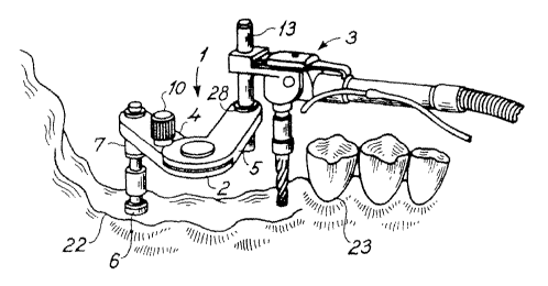
in Fig. 1 the system according to the invention is denoted 9 comprising a
paralleling
apparatus 2 and a dental handpiece 3. !n Fig. 1 the paralleling apparatus 2 is
consisting of a first arm 4 and a second arm 5 each having. a proximal end 24,
26
and a distal end 25, 27. The arms 4 and 5 are pivotably connected through a
hinging
means having a pin T8. The arms 4 and 5 are pivotable around an axis~through
the
centre of the pin 18.
In the distal end 25 of the first arm 4 a bare 9 is located as a means for
pivotably
connecting an anchor means 6. Said anchor means 6 may be a burr, such as a
pilot
burr or an anchor pin secured in the jaw, the 'use of which is designed as an
alignment tool for drilling second holes in the jaw. Thus in use the
paralleling
apparatus 2 is arranged in relation to the anchor means 6 so that attachment
means
9 slides over anchor means 6. It is preferred that the anchor means fi is
provided
with a collar, in order to determin~ the final position of paralleling
apparatus 2 in
~ relation to the anchor means 6.
In another embodiment a bush 7 is arranged in _the attachment means 9, said
bush
7 then being constructed to receive the free end of the anchor means 6. The
bush 7
is preferably provided with a collar 8 as well as a stopper mechanism so that
the
anchor means 6 cannot protrude further than to a predetermined level through
the
2o bore 9. Ttie outer diameter of the bush 7 is corresponding the inner
diameter of the
bore 9, leading to substantially no tolerance between the attachment means 9
and
the bush in the plane perpendicular to the axis of the anchor means fi. The
inner
diameter of the bush 7 is corresponding to the outer diameter of the anchor
means
6. In particular when the anchor means 6 is a burr, such as a pilot burr, it
is of
importance that various bushes 7 having different inner diameter are available
for
receiving various burrs.
Another embodiment of an anchor member according to the invention is shown in
Fig. 7. Here the anchor member 71 has a shaft 72 which consists of a lower
portion
73, an upper portion 74 and a butt 75. The diameter of the butt 75 is greater
than
the diameter of the lower portion 73, the diameter of the upper portion 74,
and the
diameter of the bore 9 in 'the distal end 25 of the first arm 4. When the
lower portion
73 of the anchor member 71 inserted in the hole in the jaw, the butt 75 rests
on the
surface of the jaw, and when the first arm 4 is arranged on the anchor member
75
by having the upper portion 74 inserted into the bore 9, the position level or
height of
AMENDED SHEET
CA 02426211 2003-04-18 ,
Df-C000062~
21-12-200'1
P 415 DK01
" . 12
' ~ ' the firsts arm may be determined by the height of the butt 75. By using
anchor
members with different butt heights, the position level of the first arm may
be varied.
Turning back to Fig. 1, in the distal end 27 of the arm 5 a bore 28 is located
as the
attachment means for pivotabiy attaching a leading pin 13 of .the adapter
means 14
of the dental handpiece 3. The leading pin 13 is designed to fit slidingly in
the bore
28. In preferred embodiment a bush 11 is arranged in the bore 28 for receiving
the
leading pin 13. The bush 11 is preferably provided with a collar 12.for
determining
an end position of.the bush 11. The bush 11 may be an open-ended bush whereby
1t7 the leading pin 13 is capable of sliding through the bush 11. In another
embodiment
the bush ,11 is provided with a stopping mechanism so that the leading pin 13
is
forced to stop at a predetermined paint when entered into the bush 11. By
using
bushes of the latter type in combination with corresponding bushes for the
anchor
. means it is possible to correct for the different heights in the jawbone and
thereby
determine the precise depth of the hole to be drilled.
As may be seen fram Fig. 1 the burr 16 does not pass through any of the arms 4
and 5 during the drilling function, thus the drilling axis of the burr is at a
distance to
the second arm.
A fixation screw 10 is located adjacent the hinging means for cocking the arm
4, 5 in
a predetermined angle in relation to each other. The fixation screw 10 may be
activated before the paralleling apparatus 2 is arranged in situ, this being
particularly
relevant if the drilling action is performed on a model prior to being
performed in situ.
Alternatively, the frxation screw 10 maybe activated after the paralleling
apparatus 2
has been arranged In situ prior to the drilling action.
In Fig. 2 each of the arms 4, 5 of the paralleling apparatus ~ are provided
with a
recess 19, 20 providing a greater range of movement of the burr while at the
same
time providing a lighter instrument.
Fig. 3 shows a dental handpcece 3 according to the invention. The handpiece 3
is
provided with a means 17 for connection to a rotating energy source, a burr
attachment means 21 for releasably receiving the burr and an adapter means 14
for
~ attaching the paralleling apparatus 2. In Fig. 3 the adapter means 14 is an
AMENDED SHEET
~ -'- CA 02426211 2003-04-18 _
Di~0000t72a
v 21-12-2001 p 415 DK01 ' ~ '
13
integrated part of the head of the dental handpiece whereby the risk of
tolerances,at
this point is eliminated. The adapter means 14 is provided with a bore 15 for
receiving the leading pin 13. During the drilling function the leading pin 13
is fixed in
the bore 15. 1n one embodiment of the invention it is possible to adjust the
position
of the leading pin 13 prior to drilling, it is however often preferred that
the leading pin
13 is permanently fixed and any height adjustments are carried out by use of
various
bushesll.
Fig. 4 a shows a partially cross-section view of a bush, such as a bush 11 for
receiving the leading pin 13'. The bush 11 is provided with a stopping
mechanism 29
serving as a stopping mechanism for the leading pin 13' in order to
predetermine the
drilling depth possible. The bush 13' is furthermore provided with a costar
12'. Fig. 4
b shows a partially cross-section view of a bush, such as a bush 11 for
receiving the
leading pin 13". The bush 11, is not provided with a stopping mechanism
whereby
the leading pin 13° may be entered through the bush 11. The bush 11 is
furthermore
provided with a collar 12'".
In Fig. 5 and Fig. 8 the system 1 according to the invention is arranged in
situ for
drilling a second hole in the jaw bone 22 adjacent the existing teeth ~3 of
the jaw. A
first hole has been drilled in the jawbone, a so-called pilot hole, wherein
the anchor
means 6 is arranged. Then the paralleling apparatus 2 is arranged by sliding
arm 4
including a bush 7 over the free end of the anchor means 6 situated in the jaw
bone.
After having decided the required angle between the arms 4, S the fixation
screw 10
is activated to interlock the two arms 4, 5. Thereafter the dental handpiece 3
is
positioned with the leading pin 13 into the bore 28. The final adjustments
before
drilling are carried out by rotating the paralleling apparatus 2 about an axis
through
the centre of the anchor means 6 and rotating the dental handpiece 3 about an
axis
through the leading pin 13. The longitudinal axis of the hole drilled is
parallel with the
longitudinal axis through the anchor means. The next hole to be drifted .may
be
pertormed by simply releasing the fixation screw, rotating the paralleling
apparatus'2
into a new position, interlocking the two arms 4,5 and perform the drifting
action.
In case the position of the next hole is not reachable by rotating arm 5 in
relation to
arm 4, it is possible to invert the paralleling apparatus 2 as discussed
above.
Thereby another range is reachable for drilling the necessary hofe~for the
implant.
AMENDED SHEET
CA 02426211 2003-04-17
WO 01/34055 PCT/DK00/00622
14
In some cases a further distance piece or arm may be used. In Fig. 8 is shown
a
distance piece or distance arm formed as a two -step staircase. The distance
arm
80 has a first end or first step 81, a connecting part 82 and a second end or
second
step 83. Here the upper surface 84 of the first step 81 is positioned below
the lower
surface 85 of the second step 83. The attachment means 9 of the first arm 25
can
be pivotably connected to the first step 81, where pivot means corresponding
to the
upper part of the anchor means 6 inserted in the jaw may be provided. The
second
step 83 is provided with a bore for being pivotably connected to anchor means
6
inserted in the jaw. Furthermore locking means may be provided for securing
the
second step 83 to the anchor means 6 in the jaw.
The invention further relates to a method for parallel insertion of a dental
implant in a
jawbone comprising establishing a first hole in the jawbone,
arranging an anchor means in the hole,
using said anchor means as a pivot guide for an arm of a system as defined
above,
guiding a handpiece attached to the system said handpiece comprising a burr
for drilling second holes) in the jaw bone that are parallel with the first
hole, and
inserting the implant.
In the present context the jawbone is intended to include jawbone as such, a
tooth
root and/or an existing tooth. Also the method is useful for providing holes
in the
jawbone being parallel with attachments on existing teeth. In the latter the
anchor
member may be inserted in the attachment.
The handpiece may be provided with a direction indicated, in particular as a
guidance for the dentist when making the first hole, i.e. before the
parallelling device
is introduced.
Before carrying out the method positioning of the apparatus may be examined in
a
model of the jaw. In this case it is advantageous to fix the arms of the
system in
SUBTITUTE SHEET (RULE 26)
w CA 02426211 2003-04-18
DK000062~
21-'12-2001 . '
P 415 DICOi
relation to each,other in a predetermined angle prior to the system being
attached to
the anchor means, because the predetermined angle may be determined in the jaw
model.
5 When the height Level of the second hole differs from that of the first hole
a bush for
receiving the anchor means is preferably arranged in the frst arm, and a bush
for
receiving a leading pin of the handpiece is preferably arranged~in the second
arm,
said bushes bearing collars in different levels providing far drilling the
second hole in
another height than the first hole.
During the drilling function it is preferred that the burr is cooled. In
normal dental
practice the burrs a preferably water cooled during drilling. Due to the
arrangement
of the burr, whereby the drilling axis does not pass any of the arms it is
possible to
water coot the burr during drilling. As a further advantage of the present
invention it
is possible to observe the burr during the drilling function. Thereby the
function may
be monitored in particular with respect to the actual water coating and/or the
proceeding of the burr and the appearance of jaw chips.
lPet an advantage of the present invention is the ability of inserting the
implants
themselves by use of the system. Some implants are to be inserted by means of
a
drilling means, such as the dental handpiece, and these implants are mostly
provided with a maridritl fitting into the burr securing means. of the dental
handpiece.
Accordingly, in one embodiment the invention relates to a method wherein the
insert
is inserted by arranging the mandrill in the securing means of the dental
handpiece
~5 attaching the handpiece to the paralielfng system and rotating the implant
into the
second hose in the jaw. In case the implant does not require a pre-drilled
hole, it is
also possible to use the present system for inserting the implant, by
replacing the
step of drilling the second hole with a step of rotating the implant into the
jaw. The
implants may be any implants used for providing anchor points in the jaw to
which
supports are made for a single tooth, several teeth, bridges and/or prosthetic
devices, such as partially or total prosthetic devices. ,
A further object of the present invention is the use of the system described
above for
drilling implant holes for inserting dental implants. Since the system may be
used
with burrs of any diameters the system may be used for inserting a wide
variety of
AMENDED SHEET
CA 02426211 2003-04-17
WO 01/34055 PCT/DK00/00622
16
implants. Thus, the system may be used to insert implants of any fabricate,
such as
ITI, Branemark, Astra, 3i, and Frialith.
SUBTITUTE SHEET (RULE 26)