Note: Descriptions are shown in the official language in which they were submitted.
CA 02426714 2003-04-09
WO 02/37075 PCT/DKO1/00721
1
Optical amplification in coherent. optical frequency modulated continuous
wave reflectometry
The present invention relates to an apparatus for optical coherence
reflectometry, in
particular for optical coherence tomography.
Background
Optical low-coherence reflectometry (OLCR) is used for example for analyzing
in-
homogeneities in optical waveguides and optical devices. In this method light
is
transmitted down the optical fibre and light resulting from the interaction
with an in
homogeneity in the optical fibre is back-scattered. The light is split into
two arms, a
sample arm and a reference arm. When the optical pathlength in the sample arm
matches time delay in the reference arm coherent interFerence occurs and the
dis
tance the light has travelled in the sample arm may be determined.
Most known devices, use broadband light sources eg. superluminescent diodes,
with a short coherence time, and they need a scanning mirror to record the
depth
resolved backscattered signal. In other systems a tunable laser is used as the
light
source, whereby, instead of moving the mirror, the wavelength of the laser can
be
varied to record the backscattered signal. This principle is discussed in
Haberland,
U.H.P. et a(., "Chirp Optical Coherence Tomography of Layered Scattering
Media"
as well as in US 5,956,355 (Swanson et al.). The method is often referred to
as co-
herent optical frequency modulated continuous wave (FMCW) reflectometry.
OLCR can be extended through the use of polarized light. The light field
towards the
reference and sample is then polarized. After combining the light field
reflected from
the reference and the sample, the combined light field is split up again into
two new
light fields with perpendicular polarization states. Through this method the
birefrin-
gent properties of the sample can be investigated in addition to the
information ob-
tainable with ordinary OLCR adding to the systems ability to discriminate
between
certain types of materials within the sample. This method also applies to OCT
often
referred to as polarization sensitive OCT (PS-OCT), as well ~as coherenfi
optical
FMCW reflectometry.
CA 02426714 2003-04-09
WO 02/37075 PCT/DKO1/00721
2
Optical low-coherence reflectometry is also used in the imaging of 2-
dimensional
and 3 dimensional structures, eg. biological tissues, in this respect often
referred to
as optical coherence tomography (OCT). OCT can be used to perform high-
resolution cross-sectional in vivo and in situ imaging of microstructures,
such as in
transparent as well as non-transparent biological tissue or other absorbing
and/or
random media in generel. There are a number of applications for OCT, such as
non-
invasive medical diagnostic tests also called optical biopsies. For example
cancer
tissue and healthy tissue can be distinguished by means of different optical
proper-
ties. Coherent optical FMCW reflectomefiry also applies to the above-mentioned
cases.
In order to optimize optical low-coherence reflectometry measurements and
imaging
various suggestions to increase signal-to-noise ratio (SNR) have been
discussed in
the art.
US 5,291,267 (Sorin et al.) discloses optical reflectometry for analyzing
inhomoge-
neities in optical fibres. In US 5,291,267 amplification of the light
reflected from the
optical fibre is conducted. In particular US 5,291,267 suggests to use the
light
source as an amplifier in order to save costs.
WO 99/46557 (Optical Biopsies Technologies) discusses SNR in a system wherein
a reference beam is routed into a long arm of an interferometer by a
polarizing
beamsplitter. In general the reference suggest to include an attenuator in the
refer
ence arm to increase SNR. In a balanced setup the reference on the other hand
.
suggests to increase the power of the reference arm in order to increase SNR.
In "Unbalanced versus balanced operation in an optical coherence tomography
system" Podoleanu, A.G., Vol. 39, No. 1, Applied optics, discussed various,
methods
of increasing SNR in unbalanced and balanced systems, respectively. Reduction
of
power in the reference arm was suggested as well as reduction of fibre end
reflec
tions to increase the SNR.
Optical low-coherence tomography reflectometry and coherent optical FMCW re-
flectometry obtain the same information about the sample being investigated,
and, in
this respect, they may be considered similar.
CA 02426714 2003-04-09
WO 02/37075 PCT/DKO1/00721
3
The present invention relates to an optimisation coherent optical FMCW
reflectome-
try whereby an increase of the SNR is obtained leading to a better result of
the
measurements, in particular in relation to penetration depth of the system, so
that
the penetration depth increases, when the SNR increases.
Summary of the invention
Thus, the present invention relates to an apparatus for optical coherence
reflecto-
metry comprising
- a wavelength scanning laser source for providing a light signal
- splitting means for dividing said light signal into a first light field and
a second
light field,
- means for directing the first light field to a sample, and means for
directing a first
reflected light field from the sample, wherein' an optical amplifier is
inserted in
the first reflected light field, said optical amplifier being different from
the light
source, and means for directing the amplified first reflected light field to a
com-
bining means, so that the amplified first reflected light field is directed to
the
combining means through another route than a route through the splitting means
for dividing the fight signal,
- means for directing the second light field to the combining means,
- combining means for receiving said amplified first reflected light field and
said
second light field to generate a combined light signal, and
- at least one detecting means for detecting the combined light signal and out-
putting detection signals.
In the present context the term "optical coherence reflectometry" is used in
its nor-
mal meaning, and in particular the term means optical coherence FMCW reflecto-
metry.
CA 02426714 2003-04-09
WO 02/37075 PCT/DKO1/00721
4
Furthermore, the term "wavelength scanning laser source" means a frequency-
tuned
laser having a tunable longitudinal cavity mode and a center tunable
wavelength, for
example as described in US 5,956,355:
The present apparatus offers a better signal-to-noise ratio (SNR) whereby an
in-
crease of the maximal penetration depth is obtained. Thereby, the apparatus ac-
cording to the present invention is especially useful for obtaining optical
biopsies of
transparent as well as non-transparent tissues.
In particular a combination of the arrangement of amplification discussed
above and
reduction of fibre end reflections increases the signal-to-noise ratio leading
to an
improved system.
The term "sample path" or "sample arm" is used to define the route travelled
by the
light from the light source to the sample and reflected from the sample to the
com-
bining means. In the present context the light field and routes relating to
the sample
arm is denoted the first light field and the first light route, respectively.
Correspondingly the term "reference path" or "reference arm" is used to define
the
route travelled by the light from the light source to the combining means. In
the pre-
sent context the light field and routes relating to the reference arm is
denoted the
second light field and the second light route, respectively. It is often
convenient to be
able to alter the optical length of the second light route. This may be
accomplished
by insertion of reflection means where the position of these may be scanned or
by
using a so-called fiber-stretcher well known in the art.
In another aspect the present invention relates to a method for providing a
result of
a sample comprising
- . establishing a wavelength scanning laser source for providing a light
signal,
- splitting said light signal into a first light field and a second light
field,
- directing the first light field to a sample, and the second light field to a
reference
path,
CA 02426714 2003-04-09
WO 02/37075 PCT/DKO1/00721
- receiving the first reflected light field from the sample, optically
amplifying the
first reflected light field, and directing the first reflected light field in
a combining
means,
5 - receiving the second light field,
- combining said amplified first reflected light field and said second light
field to
generate a combined light signal,
- detecting the combined light signal obtaining detection signals, and
- processing the detection signals obtaining the result of the sample.
In the present context the term "result of the sample" may refer in coherent
optical
FMCW reflectometry to the image of the sample obtained. When using the present
invention in coherent optical FMCW reflectometry in optical fibres used for
example
in the communication technology the result relates to the signal obtained,
such as a
signal relating to the distance to an inhomogeneity in the device under test.
Drawings
Fig. 1 shows an unbalanced conventional coherent optical FMCW reflectometry
system according to prior art, wherein an attenuator has been inserted in the
refer-
ence arm.
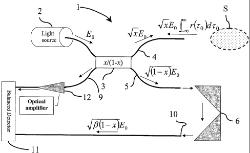
Fig: 2 shows a balanced apparatus according to the invention, wherein the
amplified
first reflected light field is directed to the combining means through another
route
than a route through the splitting means. A y-coupler is inserted in the
sample arm
to receive the reflected light field from the sample.
Fig 3 shows the balanced detection means of Fig. 2 in detail.
Fig. 4 shows a balanced apparatus as in Fig. 2 wherein an optical circulator
has
been inserted instead of the beam splitting means in the sample.
CA 02426714 2003-04-09
WO 02/37075 PCT/DKO1/00721
6
Fig. 5 shows a balanced system chosen as reference system. The system is
similar
to the system shown in Fig. (2) except for omittion of the optical amplifier
and the y-
coupler in the sample part. The y-coupler is omitted since it is no longer
necessary
for the light to follow a different path to and from the sample.
Fig. 6 shows the optimum splitter ratio for the system shown in Fig. (2)
investigated
in the absence of an optical amplifier, i.e. the amplification factor is set
to 1 and the
optical noise added from the amplifier is set to zero. The SNR of the system
is com-
pared to the reference system, where both systems are used in the uncoated
case.
Fig. 7 shows the optimum splitter ratio for the system shown in Fig. (2)
investigated
in the absence of an optical amplifier, i.e. the amplification factor is set
to 1 and the
optical noise added from the amplifier is set to zero. The SNR of the system
is com-
pared to the reference system, where both systems are used in the coated case.
Fig. 8 shows the effect of including an optical amplifier on the novel system
shown in
Fig. (2). The SNR of the novel system is compared to that of the reference
system
Fig(5), i.e. SNR~o~e~ / SNR~eference~ where both systems are used in the
uncoated
case.
Fig. 9 shows the effect of including an optical amplifier on the novel system
shown in
Fig. (2). The SNR of the novel system is compared to that of the reference
system
Fig(5), i.e. SNR~ove~ / SNRrefere~ce~ where both systems are used in the
coated case.
Fig. 10 shows the optimum splitting ratio for the novel system shown in Fig.
(2), with
the optical amplifier set at a fixed amplification factor of 20dB. The SNR of
the novel
system is compared to the reference system Fig(5), where both systems are used
in
the uncoated case.
Fig. 11 shows the optimum splitting ratio for the novel system shown in Fig.
(2), with
the optical amplifier set at a fixed amplification factor of 20dB. The SNR of
the novel
system is compared to the reference system Fig(5), where both systems are used
in
the coated case.
Fig. 12 shows the relative SNR shown as function of the thermal noise for the
sys-
tem shown in Fig. (4), where the splitting ratio is set to the optimum setting
and r"~d
CA 02426714 2003-04-09
WO 02/37075 PCT/DKO1/00721
7
is taken as the coated case.
Fig. 13 shows a balanced apparatus according to the invention, wherein only
the
first reflected light field is amplified by the optical amplifier and
hereafter directed to
the combining means.
Fig. 14 shows the optimum splitter ratio for the system shown in Fig. (-13)
investi-
gated in the absence of an optical amplifier, i.e. the amplification factor is
set to 1
and the optical noise added from the amplifier is set to zero. The SNR of the
system
is compared to the reference system, where both systems are used in the
uncoated
case.
Fig. 15 shows the optimum splitter ratio for the system shown in Fig. (13)
investi-
gated in the absence of an optical amplifier, i.e. the amplification factor is
set to 1
and the optical noise added from the amplifier is set to zero. The SNR of the
system
is compared to the reference system, where both systems are used in the coated
case
Fig. 16 shows the effect of including an optical amplifier on the novel system
shown
in Fig. (13). The SNR of the novel system is compared to that of the reference
sys-
item Fig(5), i.e. SNR~o~e~ / SNR~eference~ where both systems are used in the
un-
coated case.
Fig. 17 shows the effect of including an optical amplifier on the novel system
shown
in Fig. (13). The SNR of the novel system is compared to that of the reference
sys-
tem Fig(5), i.e. SNRnove~ / SNRrefere~~e, where both systems are used in the
coated
case.
Fig. 18 shows the optimum splitting ratio for the novel system shown in Fig.
(13),
with the optical amplifier set at a fixed amplification factor of 20dB. The
SNR of the
novel system is compared to the reference system Fig(5), where both systems
are
used in the uncoated case.
Fig. 19 shows the optimum splitting ratio for the novel system shown in Fig.
(13),
with the optical amplifier set at a fixed amplification factor of 20dB. The
SNR of the
novel system is compared to the reference system Fig(5), where both systems
are
used in the coated case.
CA 02426714 2003-04-09
WO 02/37075 PCT/DKO1/00721
8
Fig. 20 shows the SNR of the novel system shown in Fig. (4), relative to the
opti-
mum reference system, as a function of the splitting ratio x/(1-x) in the
uncoated
case. The optical amplifier is set at a fixed amplification factor of 20 dB.
The opti-
mum splitting ratio for the set of parameter values chosen as an example is
found to
be 75.21 /24. 79.
Fig. 21 shows the SNR of the novel system shown in Fig. (4), relative to the
opti-
mum reference system, as a function of the splitting ratio x/(1-x) in the
coated case.
The optical amplifier is set at a fixed amplification factor of 20 dB. The
optimum
splitting ratio for the set of parameter values chosen as an example is found
to be
7559/24.41.
Description of the drawings
In Fig. 1 an unbalanced detection scheme, not according to the invention, is
shown
for comparison reasons. The optical coherence system is denoted 1. A light
source ,
2 provides a light signal that is directed to a splitting means 3 for dividing
said light .
signal into a first light field 4 and a second light field 5. The splitting
ratio in Fig. 1 is
set to 50/50. The first reflected light 9 and the second light 10 is combined
by the
splitter means 3 and a combined signal is directed to the detector 8. The
second
light field reflected from the reflection means 6 is attenuated by attenuator
7.
In Fig. 2 a detection scheme according to the invention is depicted. The
optical co-
herence system is denoted 1. A light source 2 provides a light signal that is
directed
to a splitting means 3 for dividing said light signal-into a first light field
4 and a sec-
ond light field 5. The splitting ratio may be set to any suitable ratio,
exemplified by
the ratio x/1-x. The first reflected light field 9 is directed back fihrough
another route
than to the splitting means 3, and amplified in the optical amplifier 12, and
thereafter
directed to the balanced detection means 11 comprising a combining means. The
second light field 10 reflected from the reflection means 6 is also directed
to the bal-
anced detection means 11. The reflection means 6 is shown as a so-called
corner
cube configuration.
CA 02426714 2003-04-09
WO 02/37075 PCT/DKO1/00721
9
The balanced detection means 11 is shown in detail in Fig. 3 comprising a
combin-
ing means 13, exemplified by a splitter having a splitting ratio of 50/50,
capable of
splitting the combined signal into first split signal 14 and second split
signal 14'. The
split signals 14, 14' are directed to the detectors 8, 8' respectively. The
two detected
split signals are subtracted to obtain an output signal. The output signal may
be out-
put via 15 to a printing means, a display and/or a storage means.
In Fig. 4, a refinement of the system 1 shown in Fig. 2 is shown. To avoid the
reduc-
tion of the first reflected light field 9 by the splitting means 3, an optical
circulator 16
is inserted to direct substantially all the light power in the first reflected
light field 9 to
the optical amplifier 12.
In Fig. 13 a preferred detection scheme according to the invention is
depicted. The
optical coherence system is denoted 1. A light source 2 provides a light
signal,that is
directed to a splitting means 3 for dividing said light signal into a first
light field 4 and
a second light field 5. The splitting ratio may be set to any suitable ratio,
exemplified
by the ratio x/1-x. The first reflected light field 9 is directed back to the
splitting
means 3. After the splitter, the first reflected light filed 9 is - due to the
nature of the
splitter used - reduced by the factor (1-x) and directed to the optical
amplifier 12,
and thereafter to the balanced detection means 11 comprising a combining
means.
The second light field 10 reflected from the reflection means 6 is also
directed to the
balanced detection means 11. The reflection means 6 is shown as a so-called
cor-
ner cube configuration.
Detailed description
The present invention relates to an apparatus for coherent optical FMCW
reflecto-
metry, in particular optical coherence tomography.
One important aspect of the present invention is the route of the light field
in the
sample arm. The first reflected light field is amplified before being received
by a
combining means, said combining means being capable of receiving the first re-
fleeted light field from the sample arm as well as the second light field from
the ref-
erence arm. The amplified first reflected light field is directed to the
combining
CA 02426714 2003-04-09
WO 02/37075 PCT/DKO1/00721
means through another route than a route through the splitting means for
dividing
the light signal from the light source into the sample arm and the reference
arm,
respectively. Thereby, it is possible to direct substantially all light energy
from the
first reflected light field to the combining means, and to obtain fully the
utilisation of
5 the amplification of the first reflected light field. In other words by the
present inven-
tion the amplified first reflected light field is directed to the combining
means, so that
only the reflected light field is amplified by the optical amplifier.
Another important aspect of the invention is that the optical amplifier
inserted in the
10 first reflected light field is different from the light source so that the
effect of the light
source may be regulated independent of the degree of amplification. In
particular
when using the apparatus in coherent optical FMCW reflectometry certain safety
regulations for the power density towards the sample has to be observed to
reduce
the risk of damages to the sample under examination, such as biological
tissue.
Light Source
The wavelength scanning laser source provides the light signal for use in the
method and system.
The wavelengths scanned are adjusted to the purpose of the analysis performed
with the apparatus. The wavelengths are mostly selected in the range from 500
nm
to 2000 nm. For non-transparent solid tissue the wavelength is normally
selected in
the range from 1250 nm to 2000 nm.
For retinal examinations the wavelength is mostly selected in the range from
600 nm
to 1100 nm.
Balancedlunbalanced system
In general the system or apparatus according to the invention may be
constructed
as either an unbalanced system or a balanced system. The terms unbalanced and
balanced are used in the normal meaning, ie. an unbalanced system refers to a
system having one detecting means, whereas a balanced system refers to a
system
having two detecting means, wherein each detector receives signals from the
sam-
CA 02426714 2003-04-09
WO 02/37075 PCT/DKO1/00721
11
ple arm as well as from the reference arm. In a balanced system the signals
from
the two detectors are subtracted from each other in order to obtain the
result.
Also a double balanced system may be used in the apparatus according to the in-
vention, a double balanced system referring to a system comprising four
detecting
means.
Noise
The noise in the apparatus or system according to the invention is the total
sum of
noise sources in the following parts:
~ Optical noise, such as noise from the light source and noise from the
optical
amplifier.
~ Receiver noise, such as thermal fluctuations in the electronic parts and
shot
noise.
The optical noise from the light source is manifested as the phase noise
relating to
the first reflected light and phase noise relating to the second light as well
as phase
noise from a mixture of both.
In the following calculations, a specific configuration for the balanced
detection
scheme applied to low coherent reflectometry has been chosen. However, the
added benefit of introducing an optical amplifier with respect to the signal-
to-noise-
ratio also applies to other realizations of balanced detection and double
balanced
detection schemes.
For the following calculation a balanced detector system is assumed comprising
of
two detectors and a fiber-optic splitter as shown in Fig. 3.
The receiving device is assumed to receive two light fields, see Fig. 3: From
the
reference arm the field is E,~~(t) having the intensity I~e~(t) from the
sample the field is
Esam(t) with intensity Isam(t).
CA 02426714 2003-04-09
WO 02/37075 PCT/DKO1/00721
12
Assuming that the coupler used in the balanced detector, see Fig. 3, is
symmetric,
the field incident on each detector 1 and detector 2 respectively can be
written as
r~
El (t) = elw, a be E am (t)
Ea (t) be;~ a E,~.t (t)
(1)
where ~p~ and ~p expresses phase changes due to the coupler, t the time,
j =and a and b are coupling constants. It is known from the art that if the
cou-
pier is assumed lossless this constraint will mean that a2 + b2 = 1 and ~p =
~~r12. For a
50/50 coupler a = b = 1/~2. Thus for the balanced detector the incident fields
are:
E, (t) 1 1 e~m2 ESa"~ (t) .
E2 (t) - ~ e«~a 1 ~ Eref (t)
(2)
where the common phase change ~p ~ has been assumed zero without loss of gen-
15, erality. Using this it is straight forward to calculate the electrical
current i~ and i~ in
each detector due to a square law detection of the incident light power:
i,(t) _ 1 a Isu~»(t)+I~~f(t)+Esa,~(t)Eref(t)e m2+E_a~n(t)Er~f(t)emz
l2 (t) ~' jsam (t) + I ref (t) -~- Esam (t)Eref (t)ema + Esarn (t)Eref (t)e
i~t~2
(3)
a = rielhv is the responsivity of the photodetectors used in a balanced system
setup
where a is the electron charge, h Planck's constant, v the average wavelength
of the
light source, ri the quantum efficiency of the photodetectors. Since the
balanced
detector detects the difference between the two currents, the received
electrical sig-
nai i(t) becomes:
i(t) _ -ai(Esan= (t)E ~f (t) - Esa,~ (t)Er~f (t))
(4)
CA 02426714 2003-04-09
WO 02/37075 PCT/DKO1/00721
13
FMCW spectrum
The signal. in a FMCW system is obtained through a narrow line width light
source
where the frequency is scanned, and the resulting signal current is Fourier-
transformed to obtain the desired information. If the optical frequency is
scanned
linearly and the source is assumed to only exhibit phase noise, the field from
the
source can be written as
Esot~r~~ {t~) = Eo eXp~J Wt~~~ + (Pr~ )~
=Eo exp~(~ot~+~yt~z +~Pr)~
(5)
where colt) is the angular frequency as a function of time, c~ the angular
frequency
offset, y the frequency scan speed Eo is the amplitude and cpt is the random
fluctua-
tion phase at time t'. The reference field and the field from the sample arm
originate
from the same source and can be written as:
Er~f(t)=E,. exp~Wot+~cytz +cpr)J
(6)
E.sa~n~t)_~ j".Uo)ESeXP~~~o~t-I-2o)+TIY~t+2o~z+(Pt+zo)~zo~
{7)
where zo is the time delay due to difference in optical path length between
the sam-
ple and reference arm, E~ and ES the respective amplitudes and r(zo) is a
function
describing the intensity reflectivity profile of the sample arm. This
reflectivity profile
includes the reflectivity profile of the sample and any undesired reflections
in the
sam,ple'arm e.g. from lenses, fiber ends, etc. Next, we investigate the
received sig-
nal due to a single reflection in the sample arm i.e. the case where r(~o)
=8(zo),
where 8 is the Dirac delta function. Adapting the calculation of the spectrum
of the
received photocurrent given by S. Venkatesh and W. Sorin ("Phase Noise Consid-
erations in Coherent Optical FMCW Reflectometry", J. of Lightw. Tech., VOL 11,
No.
CA 02426714 2003-04-09
WO 02/37075 PCT/DKO1/00721
14
10, 1993) to a balanced system the single sided spectrum of the signal current
is
found to be
a EZ -2ex -I f/.' Y ~~ f~)
s
+ 4z~ 1-ex -2°z cos~2~cI2°I(f-.fU))+sin~2~I2°I(f-fv))
1+ ZTCZ 2Tt2~(f-fa)
°Icf-f>>~
($)
where fb=yso is the beat frequency due to path length difference between the
refer-
ence and sample fields, z~ 1/2~y is the coherence time of the light source and
0y
is the full width half max (FWHM) of the line width of the source.
The first term of Eq.(8) is the signal due to the reflection in the sample
arm, and the
second term is a broadband noise contribution due to the phase noise of the
light
source. Inspecting Eq.(4) it is clear that since there is no mixing terms of
the sample
field with itself the current resulting from multiple reflections in the
sample will be a
superposition of the current resulting from each reflection had it been alone.
Thus,
the single sided spectrum of the signal current is found to be
-I
aZEY E,s = 2ex z~Y YC Y
+~ 42~Y'(2°) 2 .1_ex -2°2
co~~Iz°I(f_fb))+sinL2~Iz°I(f'-fb))
1+ 2~zz 2~z~(f-f~)
( I °I~-f~))
(9)
Optical Amplification
In this calculation an optical amplifier is modeled to amplify the incoming
light and
add optical noise due to intrinsic amplifier noise. Hence, the light intensity
emitted
from an optical amplifier is given by
. . ~I our ~ WT \I r" J + ~1 ~,~~.~~ ~~
(10)
CA 02426714 2003-04-09
WO 02/37075 PCT/DKO1/00721
where G is the amplification factor, I;" the intensity of he incident light,
and (noise the
intensity due to intrinsic amplifier noise.
The term (noise added by the optical amplifier contributes to the system
noise in two ways. Firstly, through a mixing term with the reference field in
the art
5 known as signal-local oscillator noise, and secondly through adding to the
shot
noise. According to the art (see e.g. N.A. Olsson, " Lightwave Systems with
optical
Amplifiers", AT&T Bell Laboratories, J. of Lightwave Tech., Vol. 7, No. 7,
1983) the
optical noise power emitted by the optical amplifier is given by
~I no~s~ ~ = Nsp (G -1)h vBo ,
10 ~ , (11)
where NsP.is the spontaneous emission factor, v the center frequency of the
optical
bandwidth .of the amplifier Bo, and h Planck's constant. The bandwidth Bo
should be
chosen to span over the wavelengths scanned by the light source.
Noise Contributions
The noise contributions are all expressed as the received noise power after
electri-
cal subtraction of the two signals received by each photodetector per unit
band-
width.
Phase noise
In Eq.(9) the second term represents the noise contribution due to phase
noise. To
estimate this contribution a realistic reflectivity profile, r(zo), of the
sample arm is
constructed where the sample is, without loss of generality, chosen to be.a
highly
scattering tissue. This profile consists of three elements: an undesired
reflection
from the optics before the sample e.g. a fiber end or a lens, the desired
reflections
inside the sample and a distributed reflectivity exponentially decreasing due
to'
backscattering within the highly scattering tissue. r(zo) is written as
~"(20) =yu»~S~Zo -2und )+~Yr exp. 2~za~zo -z~ )u'r'n exp. 2,uzo~
( 12)
CA 02426714 2003-04-09
WO 02/37075 PCT/DKO1/00721
16
where p, is the damping coefficient of the medium, r""a is the reflectivity of
the unde-
sired reflection, r; is the reflectivity of the respective discrete
reflection, and r6 is the
fraction of the light lost due to damping which goes to backscattering. The
noise
contribution from phase noise is thus
2 ~ 2 2 2
~Znhase = a Er E' S Sn
( 13)
where S"(f) is given by
1-exp[-z° z, cos(2~tlz°I( f -.fb)~+ si ~~2'~2°~(f ~.fb))
z°.
1+(2~cla°I(f-.f~)~ ' '(f-fh)
(14)
Amplifier noise
Since the system utilizes a balanced detection scheme the noise emitted by the
am-
plifier, (noise, can only contribute to the noise of the system through mixing
with the
reference field. This contribution is given by (see e.g. N.A. Olsson,
"Lightwave
Systems v~rith optical Amplifiers", AT\&T Bell Laboratories, J. of Lightwave
Tech.,
Vol. 7, No. 7, 1983):
~di o,.s~~=4azhv~I,~f~Nsp(G-I).
(15)
Shot noise
It is common knowledge within the art that the so-called shot-noise due to the
parti-
cle nature of the photon-Yo-electron conversion in the photodetectors is given
by
2
(~Zshor > = 2BaCItotal >
- tea (G~Isam ~ + ~I r~f J'+' ~1 »~a~ J)
CA 02426714 2003-04-09
WO 02/37075 PCT/DKO1/00721
17
(16)
where Itofa~ is the total light intensity entering the splitter of the
balanced detector
(see Fig. (3)).
Receiver noise
The photodetectors also have an inherent noise contribution, which is
independent
of the incident light power. There are two contributions to this noise:
Thermal noise
in the electrical circuit of the detectors and shot-noise due to dark current
in photo-
detector. The receiver noise is:
(17)
~i ~orev~Y ~._ ~~l! ermal > + ~~i~ark > = 2 4 RT Fn + 2e ~i~ark
where kb is Boltzman's constant, R the load resistance of each of the
detectors, T
the temperature, F~ the noise figure of the electrical circuit of the
detectors normally
dominated by the preamplifier, (Idark) the dark current in each detector and
the factor
of 2 is due to having two independent detectors. However, this receiver noise,
inde-
pendent of the incident light, is often more conveniently measured
experimentally.
Thermal fluctuations in the electronic parts are independent of the amount of
light
used, and 'furthermore, the thermal fluctuations may be reduced by cooling of
the
detectors, and also by optimising the construction.
Shot noise relates to the particle nature of the light. The shot noise is
proportional to
the amount of light received.
When inserting an optical amplifier in the apparatus it is inherent that in
addition to
the amplification of the signal desired the optical noise will inevitably also
be ampli-
fied.
Received signal power
From Eq.(8) is can be seen that the signal power due to a single reflection
with the
time delay to the reference zo is given by
CA 02426714 2003-04-09
WO 02/37075 PCT/DKO1/00721
18
~is~rtar~=eXP[-~°z ]azErEs~~j'(zo)dzo~
c o
(18)
when one measures the signal over a finite bandwidth: y(zo+-zo ).
Signal-to-Noise Ratio
Using the above equations it is straightforward to derive the signal-to-noise
ratio
(SNR):
2
SNR = / Zsisrtar
B ~~12 ) -I- COZ Z I -F- 'OZ Z ~'~-' ~~12
' receiver' sJtot \ arrrp l \ phase
(19)
where 8 is the bandwidth over which a signal is detected i.e. the resolution
of the
Fourier-transform of the signal current. However, as the light source is
scanned
over a finite interval, a time window is imposed upon the signal current
leading to a
convolution of the signal spectrum with the Fourier-transform of the this time
win-
dow. The width of this transform determines the resolution of the system
together
with the bandwidth of the detection system, which determines the smallest fre-
quency increment detectable. Notice, that this bandwidth is decided by ttie
scanning
of the light source and the electrical detection system, so in a comparison of
the
performance of different systems, which uses the same light source and
electrical
detector system, the bandwidth involved will be a common factor, and is thus
ig
nored for the rest of this analysis.
For a given light source, sample and electrical detector system the field
amplitudes
E~ and ES must be found according to the chosen system configuration. For this
analysis the system shown in Fig.(2) has been' chosen. From inspection it is
straightforward to see that if the light source emits the light intensity
Iso~,~e is then
Er =.J(1-x)/3~Isattree~
_ (20)
and
CA 02426714 2003-04-09
WO 02/37075 PCT/DKO1/00721
19
1
~'s - 4 a'Clsour-ce>
(21 )
where x is the coupling ratio towards the sample of the first coupler from the
source,
and ~3 is a factor describing the loss of power due to an inserted device for
altering
the optical path length of the second light field, such as a mirror, retro-
reflector or
fiber-stretcher. For simplicity, and without loss of generality, the factor ~3
is set to
unity. This leads to the light intensities
~1 rej > _ \1 -'x) ~ CI source
(22)
and
1
(I Barn > - 4 x~I source > f ~ 2 ~ZO ) d20
(23)
Combining Eq.(20), Eq. (21), Eq. (22), and Eq.(23) with Eq. (13), Eq.(15), Eq.
(16),
Eq. (17) and Eq.(18) it is straight forward to calculate Eq.(19) which can be
used for
comparison of system performance between different configurations.
In analogy with this derivation, the SNR can.be derived for a wide variety of
low-coherent reflectometer systems with balanced detection and thus the
performance of such systems can be easily compared.
Splitting means
The general principle of coherent optical FMCW reflectometry is that distance
trav-
elled by the light in the sample arm is correlated to the distance travelled
by the light
in reference arm.
The light is emitted from a light source as discussed above and divided into a
first
light field and a second light field by a splitting means. The splitting means
may be
any means suitable for splitting a light signal into two light fields. The
splitting means
CA 02426714 2003-04-09
WO 02/37075 PCT/DKO1/00721
may be selected from any suitable splitting means, such as a bulk optic
splitting
means, a fibre optic splitting means, a holographic optical element or a
diffractive
optical element.
5 In one embodiment the apparatus according to the invention comprises a
splitting
means capable of dividing the light signal into the sample arm and the
reference
arm with a splitting ratio of the splitting means being substantially 50 %/50
%.
However the present inventors have found due to the location of the amplifier
as
10 well as the route of the first reflected light field that a further
increase in SNR may be
obtained when using a changeable splitting ratio, so that from 1 % to 99 % of
the
light energy from the light source is directed to the sample arm. It is
preferred that
more than 50 % of the light energy is directed to the sample, such as from 50
% to
99 % of the light energy from the light source is directed to the sample arm,
such as
15 from 55 % to 90 % of the light energy from the light source is directed to
the sample
arm, such as from 60 % to 85 % of the light energy from the light source is
directed
to the sample arm, such as from 65 % to 85 % of the light energy from the
light
source is directed to the sample arm.
20 In another embodiment it is more preferred that from 1 % to 60 % of the
fight energy
from the light source is directed to the sample arm, such as from 20 % to 55 %
of
the light energy from the light source is directed to the sample arm, such as
from
% to 50 % of the light energy from the light source is directed to the sample
arm,
such as from 40 % to 50 % of the light energy from the light source is
directed to the
25 sample arm.
Sample arm - first light field route
The apparatus according to the invention comprises means for directing the
first
30 light field to the sample. In a preferred embodiment at least a part of the
means for
directing the first light field to the sample comprises an optical fibre, so
that the
means in total comprises an optical fibre and an optical system. An optical
system
may be included for focusing the first light field to the sample. The optical
system for
example being one or more lenses.
CA 02426714 2003-04-09
WO 02/37075 PCT/DKO1/00721
21
It is preferred that the first light field is directed to the sample without
being ampli-
fied. Thereby the intensity of the first light field onto the sample is
exclusively deter-
mined by the light source. This leads to a better control of the light
intensity in the
sample arm, since the light directed to the sample conforms to the practical
limits for
sample light, such as an upper limit for the intensity to avoid damages to the
sam-
ple, and the light reflected from the sample may be amplified to the degree
neces-
sary for the SNR to be suitably increased. Thus, the amplifier is preferably
located
in a part of the sample arm by which only the reflected light is travelling.
This may be
accomplished by inserting a splitting means or a circulator to receive the
reflected
first light field from the sample, or by inserting the optical amplifier after
the first re-
flected light field has passed the splitting means used to split the light
into the first
and second light fields
In a preferred embodiment a circulator is inserted whereby substantially all
light en-
ergy reflected from the sample is directed as the first reflected light field
to the opti-
cal amplifier.
The term light field as used herein means light field as normally used for the
light in
optical fibres, but does also include a light beam as normally used in bulk
systems
and in the optical system.
Scanning head
The sample is scanned by means known in the art, such as galvanometer
scanners,
polygon mirrors, resonant scanners, a scanning head.
Amplifier
Any optical amplifier suitable for amplifying the reflected first light field
may be inter-
posed in the light route from the sample to the combining means. The amplifier
may
thus be a semiconductor, a resonant amplifier or a fibre and/or Raman
amplifier.
The amplification factor may be in the range from 1.5 to 1,000,000 times, such
as
from 20 to 500,000 times, for example from 20 to 100,000 times, such as from
20 to
50,000 times, such as from 20 to 10,000 times, such as from 20 to 1000 times,
such
as from 20 to 100 times.
CA 02426714 2003-04-09
WO 02/37075 PCT/DKO1/00721
22
Reference arm - second light route
The apparatus according to the invention also comprises means for directing
the
second light field to the combining means. In a preferred embodiment a device
is
included so that the optical path length of the second light route may be
altered. In a
preferred embodiment hereof at least a part of the directing means is
comprised of
an optical fiber and an optical fiber,stretcher. In another preferred
embodiment the
device is a reflecting means such as a mirror setup. In this embodiment at
least a
part of the means for directing the second light field to the reflecting means
com-
prises an optical fibre, so that the directing means in total comprises an
optical fibre
and an optical system. The optical system may be used for directing the second
light
field to the reflecting means, such as any kind of lenses, gratings etc. known
to the
person skilled in the art.
Attenuation of the reflected second light field may be useful when using an
unbal-
anced system, whereas attenuation of the reference arm does not add anything
further to the SNR in a balanced system.
In a preferred embodiment the reflected second light field does not pass any
splitting
means for dividing the light signal when travelling towards the combining
means. It
is an advantage to maintain as much as possible of the second light field on
the
route to the combining means. This may be accomplished by directing the second
lighf field from the splitting means to the combining means in an optical
fiber and if it
is desired to alter the optical path length of the second light route to
modulate the
properties of the fiber. This may be done through a fiber stretcher to
modulate the
physical length of the fiber or by e.g. applying heat to alter the refractive
index of the
fiber. If a reflecting means is applied to alter the optical path length the
light power
may substantially be preserved by inserting a, circulator to receive the
second light
field from the reflection means to direct the second light field directly to
the combin-
ing means.
In a preferred embodiment a circulator is inserted to receive the second light
field
whereby substantially all light energy reflected from the reflecting means is
directed
as the second light field to the combining means.
CA 02426714 2003-04-09
WO 02/37075 PCT/DKO1/00721
23
In another preferred embodiment a fiber stretcher is inserted as described
above.
The reflecting means may be any means suitable for reflecting the light in the
refer-
ence arm. The reflecting means may be a mirror or another structure having
reflec-
tive properties.
Combining means
The combining means is any suitable means capable of receiving two light
fields
and combining the light fields into at least one light signal. In a preferred
embodi
ment the combiriing means is a coupler. .
In an unbalanced system the combining means may be identical to the detecting
means.
Detecting means
The system comprises conventional detecting means. The detecting means is es-
sentially a photodetector chosen accordingly to match the source wavelength, a
combination of photodetectors arranged to make up a balanced scheme, or a com
bination of photodetectors arranged to make up a double-balanced scheme.
Furthermore, the detecting means may be a linear array of photodetectors
without or
combined with a dispersive element arranged so that the array provides depth
and
spectral information. The detecting means may also be a linear charge-coupled
de-
vice (CCD) array without or combined with a dispersive element arranged so
that
the array provides depth and spectral information.
Finally, the detecting means may be a two-dimensional array of photodetectors
without or combined with a dispersive element arranged so that the array
provides
depth and spectral information. The detecting means may also be a two-
dimensional
CCD array without or combined with a dispersive element arranged so that the
array
provides depth and spectral information.
For example, the dispersive element may be a diffraction grating (reflection
or
transmission), a prism or a combination of prisms.
End reflections
CA 02426714 2003-04-09
WO 02/37075 PCT/DKO1/00721
24
In a preferred embodiment the SNR is further increased by reducing non-sample
reflections, such as the fibre end reflections in the sample arm. By reducing
the non-
sample reflections in combination with amplification of the first light field
an increase
of the relative SNR is increased up to for example about 10 dB, such as up to
about
15 dB, for example up to about 20 dB. It has been shown that the amplification
of
the light field in the sample arm is improved additionally when reducing
reflections.
The end reflections may be reduced by anti-reflex coating the fibre ends of
the fibres
in one or both of the arms.
Also the fibre ends may be cleaved at an angle to reduce reflections, such an
angle
being at least 5 degrees, such as preferably at least 7 degrees.
The anti-reflex coating and the cleaving of the fibre ends may be used as
alterna-
tives or in combination.
Processing/displaying
The result obtained may be further processed to obtain relevant information
based
on the detection signal relating to the distance/coherence. In one embodiment
the
detection signal is sent to a computer for analysis. Depending on the object
scanned, the computer may provide an image relating to for example the tissue
scanned.
In relation to detection of inhomogeneities in for example optical waveguides,
the
computer may provide information relating to the distance to the inhomogeity
and for
example also an image of the inhomogeneity.
The result may be sent from the computer to a display and/or a printer and/or
stored
in a storage means.
Penetration depth
The parameters that govern coherent optical FMCW reflectometry performance are
longitudinal and transverse resolution, dynamic range, measurement speed, and
the
centre wavelength of the light source.
CA 02426714 2003-04-09
WO 02/37075 PCT/DKO1/00721
The depth to which an illumination field of light penetrates within turbid
media, such
biological tissue or the like, is determined by the amount of scattering and
absorp-
tion present in the media.
5
In tissue scattering diminishes rapidly with increasing wavelength throughout
the
visible and infrared wavelength regions. Absorption in tissue is dominated by
reso-
nant absorption features, and no simple scaling can be assumed. For hear-
infrared
light (~0.8 p.m), where absorption is relatively week, scattering is the
dominant
10 mechanism of attenuation. At longer wavelengths, such as 1.3 p,m, 1.55 p.m
or
1.9 p,m, scattering is minimal, and water absorption becomes increasingly
important.
The longitudinal resolution governed by the coherence length is inversely
propor-
tional to the optical bandwidth of the light source.
By the present invention the penetration depths may be increased or even
doubled
due to the increased SNR depending on the optical properties of the medium.
The transversal resolution is essentially given by the well-known diffraction
limit, i.e.
the minimum focal spot, which is the resolving power. The diffraction limit is
deter-
mined by the wavelength, the effective aperture of the beam and the focal
length of
the lens as known from the art.
The measurement speed, i.e. the time to perform a single a-scan and capture
the
interference signal, may be defined in different ways, and therefore a unique
meas-
ure for this quantity cannot be given. However, increasing the scan speed
implies
increasing the electrical bandwidth of the detecting means and this may
ultimately
lead to an increase of the receiver noise. As shown by the analysis above, the
intro-
duction of the optical amplifier amplifying the reflected light from the
sample may be
even more advantageous if the noise in the detecting means increases. In other
words, the optical amplifier may to a certain extent aid to overcome receiver
noise.
Thus, due to the amplification system according to.the present invention it is
possi-
ble to conduct a faster scanning than with state-of-the-art systems.
CA 02426714 2003-04-09
WO 02/37075 PCT/DKO1/00721
26
Transverse scanning
The light path preferably includes a transverse scanning mechanism for
scanning
the probe beam within the sample, for example an actuator for moving the
appara-
tus in a direction substantially perpendicular to the sample. Such a scanning
mechanism can have a micro-machined scanning mirror. A longitudinal scanning
mechanism can also be provided to scan in a direction parallel to the probe
beam.
Scanning allows the apparatus to create images. Longitudinal scanning in the
direc-
tion of the probe beam axis, along with scanning in a direction perpendicular
to the
axis, provides the possibility of obtaining an image of a vertical cross
section of the
sample.
It is of course understood that although it is preferred to scan the sample
apparatus
in relation to the sample, the sample may also be scanned with respect to a
station-
ary sample probe or a combination of these.
Applications
The apparatus and method according to the.present invention may be used in any
application normally applying OCT scanning as well new technical fields
wherein the
increased SNR allows the use of the present apparatus. Thus, the apparatus may
be used for so-called optical biopsies, wherein a segment of tissue, such as
the
skin, mucosa or any other solid tissue is examined by OCT to diagnose any
cellular
abnormalities, such as cancer or cancer in situ. Furthermore, any malignant
growth
may be detected by the present apparatus.
Due to the optical amplification conducted as discussed herein it is possible
to in-
crease the relative SNR, for example up to about 20 dB, such as about 17 dB,
such
as about 14 dB, drastically increasing the penetration depth of the system.
Thus,
malignacies in the skin or mucosa may be detected directly by using the
present
invention. Furthermore, the apparatus may be coupled to catheters or the like
to
scan internal body parts, such as the gastro-intestinal tract, a vessel or the
heart or
any body cavity. Also, the apparatus may be used for scanning during a
surgical
operation.
CA 02426714 2003-04-09
WO 02/37075 PCT/DKO1/00721
27
Also, the present apparatus has improved the use of OCT in ophthalmic
application
due to the increased penetration depth, such as in corneal topography measure-
ments and as an aid in ophthalmic surgery, for example for focusing on the
posterior
intraocular lens capsule-for use in cataract surgery.
The present invention may also be applied in conventional OLCR applications,
such
as detection or imaging of inhomogeneities in optical waveguides or devices,
i.e.
wherein the sample is an optical waveguide or an integrated optical device.
In another embodiment the sample may be a polymer or like structure.
In yet another embodiment the sample may be silicon-based integrated circuit.
Examples
Here follows a comparison of a coherent optical FMCW reflectometry system ac-
cording to prior art and two coherent optical FMCW reflectometry systems
according
to the present invention exemplifying the added benefit of introducing an
optical am-
plifier. The effect of using a system where all undesired reflections has been
re-
duced as much as possible e.g. through coating of all surfaces, as well as the
effect
of changing the splitting ratio on the splitter from the source, is
demonstrated. The
former case in which all surfaces are coated is referred to as the coated
case,
whereas not coating the surfaces is referred to as the uncoated case.
The system parameters used are
~I Sou,~~~ ~ =1 OmW
Scan length of the light source =100nm
2~t2 - 20MHz
Center wavelength = ~ = l OSOnm
v
_ y=2.72727~10'$Hz/s
Bo =vm~ ~vmin = 27.2727 THz
Nsn = 2
q = 0.8
Receiver noise density =-155dBinlHz
CA 02426714 2003-04-09
WO 02/37075 PCT/DKO1/00721
28
and the reflectivity profile of the sample arm is chosen to be
4
~(ZO) = juncl~~2o -Zvnd ~+~ji eXhL 21u2i J" \Z0 -2i ~+~b exh~ 21"'ZO.b
i=I
(24)
where
0.04 in the uncoated case
10-5 in the coated case
Y, =O.OOland2l =0
~Z =0.004 and z, =~~.O.Smm)
f3 =0.004and21 =~~.lmm)
f4 =0.004 and z, =~~,l,Smm)
~b =10-6 and ,u = Smm~'
and the Signal-to-noise ratio is inspected for the measurement of the
reflectivity r3
and position z3. Here an attenuation coefficient ,ut=5 mrri', a probing depth
z--2mm,
and a reflection coefficient within the sample of 0.4% have been chosen.
Example 1a
a) Choice of reference system
First, a reference system against which to compare the performance is decided.
This system can be seen in Fig. 5. Through a similar analysis as to the one
used to
derive Eq. (19), the SNR of the reference system may be found. By doing so, it
is
found that the optimum splitting ratio toward the sample is approximately 35%
and
65% towards the reference both for a system with and without coated surfaces.
A
system with this splitting ratio is chosen as reference system. This is shown
in Fig.
14 and 15 where r";,dis in the uncoated and coated case, respectively. A
system with
this splitting ratio is chosen as reference system.
CA 02426714 2003-04-09
WO 02/37075 PCT/DKO1/00721
29
In the graphs in Fig. 6 - Fig. 11, relative SNR implies that the system under
investi-
gation is compared to the corresponding reference system, which experiences
the
same conditions in terms of reflectivity, receiver noise etc. The novel system
in Fig.
2 is compared to the reference system.
b) Optimum splitting ratio in the absence of amplification
First, the splitting ratio x is investigated in the absence of an amplifier
for both the
coated and uncoated case. The SNR for this system is found from Eq. (19) by
letting
G=9 and Nsp=0. Figures 6 and 7 shows the SNR of the system shown in Fig. 2 as
a
function of the splitter ratio x relative to the reference system Fig. 3 when
rU~d is in
the uncoated and coated case, respectively.
From figures 6 and 7 it is concluded that when an optical amplifier is not
present in
the system adjusting the splitting ratio away from 50/50 is a disadvantage.
c) Effect of amplification for a constant splitting ratio
Next, the effect of the amplifier is investigated over a wide range of
amplification
factors and the splitting ratio is set to 50/50. Fig. 8 shows the increase in
SNR due
to the use of an optical amplifier in the novel system shown in Fig. 2 for the
un-
coated case and Fig. 9 shows the increase in SNR in the coated case. It is
noted
that the relative SNR is less than unity for low amplification factors. This
is due to
the amplifier having to compensate for the loss of optical signal power due to
the
extra coupler in the system under investigation and added amplifier noise.
d) Optimum splitting ratio for a fixed amplification
A conservative amplification factor of 100 (20 dB) is chosen and the effect of
choosing a different splitting ratio than 50/50 is investigated again. Fig. 10
and Fig.
11 shows the uncoated and the coated case, respectively. These graphs demon-
strate that in both cases it is an advantage to select a different splitting
ratio then
50/50 for a system using optical amplification, and that the advantage of
doing this is
highest in the coated case. In this case the SNR is imprived with about 9 dB.
e) Optical circulators and fixed amplification
CA 02426714 2003-04-09
WO 02/37075 PCT/DKO1/00721
Another realization of the novel coherent optical FMCW reflectometry system is
shown in Fig. 4, where the y-coupler in the sample part has been replaced with
a so-
called optical circulator known from the art. Obviously, the signal light
power is in-
s creased by a factor of four. Using the same parameters as above in d) for
the
coated case, the improvement in relative SNR for the realization in Fig. 4 is
31 com-
pared to 10 for the realization in Fig. 2 when both realizations are compared
to the
same reference system. ,
10 Finally, in Fig. 12 the sensitivity of the relative SNR on the receiver
noise is demon-
strated for the realization in Fig. 4. For a low thermal noise the optical
amplifier may
be a disadvantage since the noise is dominated by the noise added by the
optical
amplifier. As the thermal noise in the receiver is increased the optical
amplifier be-
comes an increased advantage because the optical noise added is gradually
15 masked by the thermal noise. For high values of the thermal noise the
advantage of
the optical amplifier is constant since the thermal noise is the dominant
noise term.
Example 1 b
20 a) Choice of reference system
The reference system chosen for this example is identical to that of example 1
a.
In the graphs in Fig. 16 - Fig. 21, relative SNR implies that the system under
inves-
25 tigation is compared to the corresponding reference system, which
experiences the
same conditions in terms of reflectivity, receiver noise etc. The novel system
in Fig.
13 is compared to the reference system. The SNR for the system shown in Fig.
13 is
easily found by replacing Eq. 21 and Eq. 23 in the substitution into Eq. 19
with
30 ES = (1-.7C~.x(Isource>
(25)
and
CA 02426714 2003-04-09
WO 02/37075 PCT/DKO1/00721
31
2
CI sam > - ~1- x~x~l source >~ ~ ~20 ~dZO
(26)
respectively.
c) Effect of amplification for a constant splitting ratio
Next, the effect of the amplifier is investigated over a wide range of
amplification
factors and the splitting ratio is set to 50/50. Fig. 16 shows the modest
increase in
SNR due to the use of the optical amplifier in the uncoated case. This is due
to the
increase in amplifier noise through mixing of the light due to the undesired
reflection
r"nd and the spontaneous noise power emitted by the amplifier. Fig. 17 show
the
increase in SNR due to the use of the optical amplifier in the coated case.
For both
cases it is noted that the relative SNR is less than unity for very low
amplification
factors. This is due to the amplifier having to compensate for the extra noise
added
by the amplifier.
d) Optimum splitting ratio for a fixed amplification
A conservative amplification factor of 100 (20 dB) is chosen and the effect of
choosing a different splitting ratio than 50/50 is investigated again. Fig. 18
and Fig.
19 shows the uncoated and coated case, respectively. These graphs demonstrate
that in both cases it is an advantage to select a different splitting ratio
than 50/50 for
a system using optical amplification although for chosen system parameters,
the
advantage is only slight and the optimum splitting ratio is 45/55. It is seen
that the
relative increase in SNR by inclusion of an optical amplifier is approximately
a factor
25 higher in the coated case compared to the uncoated case, and there is
little ad-
vantage in the uncoated case.
The system realisations analyzed above should be considered typical examples.
However, the advantage of introducing an optical. amplifier is clearly pointed
out.
Firstly, it is demonstrated that the optical amplifier may aid to overcome
receiver
noise leading to improved system performance in terms increased SNR. The
impact
CA 02426714 2003-04-09
WO 02/37075 PCT/DKO1/00721
32
of optical amplification on an coherent optical FMCW reflectometry system is
highly
dependent on the noise contribution from the receiving system, which comprises
all
components involved in obtaining an electrical signal from the optical output
e.g.
electrical amplifiers, computer data collection system etc. This sensitivity
is illus-
trated through Fig. 12, where the system with optical amplifier and optical
circulator
(shown in Fig. 4) is compared to the reference system in the coated case.
Secondly,
an optimum splitting ratio different from 50/50 has been demonstrated.
Finally, add-
ing an optical amplifier will be an increased advantage as the electrical
bandwidth of
the receiver is increased, which may lead to an increase of the receiver
noise. In
other words, the optical amplifier may to a certain extent aid to overcome the
in-
crease in receiver noise. An increase in electrical detection bandwidth is
necessary
when fast acquisition of measurement data desired e.g. for real-time imaging.