Note: Descriptions are shown in the official language in which they were submitted.
CA 02426726 2003-04-22
WO 02/068905 PCT/USO1/50311
GRAPHIC CLOSURE INDICATOR FOR COCKPIT TRAFFIC DISPLAY
TECHNICAL FIELD
This invention relates to displays of traffic in the cockpit of an aircraft
and,
more particularly, relates to displaying an indication of closure between an
Own Ship
aircraft and a selected target aircraft in response to the flight
characteristics of the
selected target aircraft satisfying certain specified criteria.
BACKGROUND OF THE INVENTION
A primary task for pilots is to be aware of nearby air traffic by maintaining
a
constant visual scan. If traffic is sighted, the pilot must first assess the
threat posed by
the intruder aircraft, then, if necessary, maneuver to avoid the aircraft.
This strategy
is termed "see-and-avoid." The effectiveness of see-and-avoid depends on the
ability
of a pilot to visually acquire an intruder aircraft early enough in the
encounter to
enable threat assessment and avoidance. A Cockpit Display of Traffic
Information
(CDTI) assists the pilot with see-and-avoid by providing a display of nearby
traffic.
A CDTI display typically displays nearby target aircraft and information about
the target aircraft, such as altitude, track, and identification information.
This
information may be received from one or more sources, including Traffic
Information
Service (TIS) from a ground-based air traffic control center, and Automatic
Dependent Surveillance-Broadcast (ADS-B) from transponders on other aircraft,
or
vehicles
The ability to easily determine from the display the movement of nearby
aircraft relative to the aircraft containing the display is especially
desirable for
effective threat assessment and avoidance. Additionally, aircraft operations
can
benefit from the timely and effective presentation of traffic information that
can assist
in decision making for the flight crew. Thus, there is a need for enhancements
to
CDTI units to provide easily-readable graphic indications of the relative
movement
and status of nearby aircraft.
SUMMARY OF THE INVENTION
The present invention is an improvement in displaying traffic information on
an aircraft display, such as a CDTI. More specifically, the invention provides
a
method and system for graphically displaying on a cockpit display a graphical
1
CA 02426726 2003-04-22
WO 02/068905 PCT/USO1/50311
indication of the rate at which an Own Ship aircraft is closing in on, or
receding from,
a selected target aircraft. This rate, which is generally referred to as a
"closure rate",
has a positive value if the Own Ship aircraft is closing in on the selected
target
aircraft, and a negative value if the Own Ship aircraft is receding from the
selected
target aircraft. The graphical indication of the rate at which the Own Ship
aircraft is
closing in on, or receding from, the selected target aircraft is generally
referred to as a
"closure indicator."
In a preferred embodiment of the invention, the system displays a closure
indicator in response, at least in part, to both of the following requirements
being
satisfied:. (1) the selected target aircraft is within a pre-determined
monitoring zone;
and (2) the track of the selected target aircraft is within a pre-determined
variation
angle of the track of the Own Ship aircraft. In an alternative embodiment of
the
invention, the system also displays the closure indicator, at least in part,
in response to
(3) the rate of closure between the selected target aircraft and the Own Ship
aircraft
being within a predetermined range of values. In a preferred embodiment of the
invention, the system is configured to display no closure indicator, at least
partially in
response to the system failing to meet one or more of the above requirements.
As noted above, a system according to a preferred embodiment of the
invention only displays a closure indicator if the first two of the above
requirements
are satisfied. However, in various alternative embodiments of the invention,
the
system is configured to display a closure indicator only if a different pre-
determined
two of the above requirements are satisfied. For example, in one embodiment of
the
invention, the system only displays a closure indicator if requirements 1 and
3, above,
are satisfied. Such a system only displays a closure indicator i~ (1) the
selected target
aircraft is within a pre-determined monitoring zone; and (2) the rate of
closure
between the selected target aircraft and the Own Ship aircraft is within a
predetermined range of values. In another embodiment of the invention, the
system
only displays a closure indicator if requirements 2 and 3, above, are
satisfied. Such a
system only displays a closure indicator i~ (1) the track of the selected
target aircraft
is within a pre-determined variation angle of the track of the Own Ship
aircraft, and
(2) the rate of closure between the selected target aircraft and the Own Ship
aircraft is
within a predetermined range of values.
In another alternative embodiment of the invention, the system only displays a
closure indicator if each of requirements 1-3 is satisfied. Such a system only
displays
2
CA 02426726 2003-04-22
WO 02/068905 PCT/USO1/50311
a closure indicator if (1) the selected target aircraft is within a pre-
determined
monitoring zone; (2) the track of the selected target aircraft is within a pre-
determined
variation angle of the track of the Own Ship aircraft; and (3) the rate of
closure
between the selected target aircraft and the Own Ship aircraft is within a
predetermined range of values.
In a further alternative embodiment of the invention, the system displays a
closure indicator if a pre-determined one of the above requirements is
satisfied. In an
additional alternative embodiment of the invention, the system constantly
displays a
closure indicator on the display screen while the aircraft is in flight.
The system is preferably configured to remove a closure indicator from
display on the display screen in response to either the Own Ship aircraft
landing or the
selected target aircraft landing.
In a preferred embodiment of the invention, the pre-determined monitoring
zone referenced above is positioned adjacent to a front portion of the Own
Ship
aircraft. This pre-determined monitoring zone is preferably a substantially
cone
shaped segment of airspace. Additionally, the cone-shaped segment of airspace
is
preferably positioned so that the apex of the cone-shaped segment of airspace
is
adjacent a front portion of the Own Ship aircraft. Furthermore, the cone-
shaped
segment of airspace is preferably oriented so that the axis of the cone-shaped
segment
of airspace is substantially co-linear with the track of the Own Ship
aircraft. In one
embodiment of the invention, the apex of the cone-shaped segment of airspace
is
immediately adjacent a front portion of the Own Ship aircraft and the axis of
the
cone-shaped segment of airspace is oriented in substantially the same
direction as the
track of the Own Ship aircraft. The vertex angle of the cone-shaped segment of
airspace is preferably about 40 degrees. In a preferred embodiment of the
invention,
the system is configured for allowing a user to at least partially modify at
least one
boundary of the monitoring zone.
Turning now to the requirement that the track of the selected target aircraft
be
within a predetermined variation angle of the Own Ship aircraft's track, the
predetermined variation angle is preferably about 20 degrees. In a preferred
embodiment of the invention, the system is configured to allow a pilot or
other user to
modify the pre-determined variation angle to account for current flying
conditions.
The closure indicator displayed by the system preferably comprises an
alphanumeric value indicating the current rate at which the Own Ship aircraft
is
3
CA 02426726 2003-04-22
WO 02/068905 PCT/USO1/50311
closing in on, or receding from, the selected target aircraft. The closure
indicator also
preferably includes a plus or minus sign immediately adjacent to the
alphanumeric
value to indicate whether the Own Ship aircraft is closing in on, or receding
from, the
selected target aircraft. The closure indicator preferably includes a plus
sign if the
Own Ship aircraft is closing in on the selected target aircraft. Similarly,
the closure
indicator preferably includes a minus sign if the Own Ship aircraft is
receding from
the selected target aircraft.
In a preferred embodiment of the invention, if the rate of closure between the
selected target aircraft and the Own Ship aircraft is within a predetermined
range of
values, the closure indicator also comprises a closing/receding indicia that
further
indicates whether the Own Ship aircraft is closing in on, or receding from,
the
selected target aircraft. In a preferred embodiment of the invention, the
closing/receding indicia comprises an upwardly-directed arrow if the Own Ship
aircraft is closing in on the selected target aircraft, and a downwardly-
directed arrow
if the Own Ship aircraft is receding from the selected target aircraft.
More particularly, the system is preferably configured to display, at least in
part in response to the closure rate being above a predetermined upper
threshold
value, a closure indicator that includes a closing/receding indicia that
indicates that
the Own Ship aircraft is closing in on the selected target aircraft.
Similarly, the
system is also preferably configured to display, at least in part in response
to the
closure rate being below a predetermined lower threshold value, a closure
indicator
that includes a closing/receding indicia that indicates that the Own Ship
aircraft is
receding from the selected target aircraft. Furthermore, in this embodiment of
the
invention, the system is configured to display a closure indicator that
includes no
closing/receding indicia if the closure rate is both: (1) equal to or above
the
predetermined lower threshold value; and (2) equal to or below the
predetermined
upper threshold value.
In a preferred embodiment of the invention, if the closure rate is above a
predetermined upper threshold value, the system displays the closure indicator
above
a symbol representing the Own Ship aircraft. Similarly, if the closure rate is
below a
predetermined lower threshold value, the system displays the closure indicator
below
a symbol representing the Own Ship aircraft. In this embodiment of the
invention, the
system is configured to display the closure indicator to one side of a symbol
representing the Own Ship aircraft if the closure rate is both: (1) equal to
or above the
4
CA 02426726 2003-04-22
WO 02/068905 PCT/USO1/50311
predetermined lower threshold value; and (2) equal to or below the
predetermined
upper threshold value.
In a preferred embodiment of the invention, the predetermined upper threshold
value is about 5 knots and the predetermined lower threshold value is about -5
knots.
The system is preferably configured to allow a user to modify either the
predetermined upper threshold value, the predetermined lower threshold value,
or
both the predetermined upper threshold value and the predetermined lower
threshold
value to accommodate current flying conditions.
In an alternative embodiment of the invention, the system is configured to
only display a rate of closure on the display screen if the rate of closure
between the
selected target aircraft and the Own Ship aircraft is within a predetermined
range of
values. In this embodiment of the invention, the system is configured to
display a
closure indicator in response, at least in part, to the closure rate being
above a
predetermined upper threshold value. Furthermore, the system is also
preferably
configured to display a closure indicator in response, at least in part, to
the closure
rate being below a predetermined lower threshold value. In this embodiment of
the
invention, the system is further configured to display no closure indicator on
the
system's display screen if the closure rate is both: (1) equal to or above the
predetermined lower threshold value; and (2) equal to or below the
predetermined
upper threshold value.
BRIEF DESCRIPTION OF THE DRAWINGS
Having thus described the invention in general terms, reference will now be
made to the accompanying drawings, which are not necessarily drawn to scale,
and
wherein:
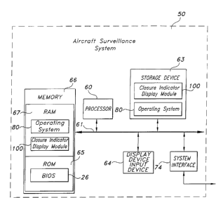
FIG. 1 is a block diagram of an aircraft surveillance system according to a
preferred embodiment of the invention.
FIG. 2 is a pictorial view of a CDTI display showing a closure indicator that
is
displayed by an aircraft surveillance system according to a preferred
embodiment of
the invention when the Own Ship aircraft is closing in on a selected target
aircraft at a
rate of 40 knots.
FIG. 3 is a pictorial view of a CDTI display showing a closure indicator that
is
displayed by an aircraft surveillance system according to a preferred
embodiment of
5
CA 02426726 2003-04-22
WO 02/068905 PCT/USO1/50311
the invention when the Own Ship aircraft is receding from a selected target
aircraft at
a rate of 60 knots.
FIG. 4 is a pictorial view of a CDTI display showing a closure indicator that
is
displayed by an aircraft surveillance system according to a preferred
embodiment of
the invention when the Own Ship aircraft is receding from a selected target
aircraft at
a rate of 4 knots.
FIG. 5 is a pictorial view of a keypad used in an aircraft surveillance system
according to a preferred embodiment of the invention.
FIG. 6 is a graphically depicted top view of a monitoring zone according to a
preferred embodiment of the invention in an example in which there is no wind
so
that the heading and track of the Own Ship aircraft are the same.
FIG. 7 is a graphical depiction of an example in which a system according to a
preferred embodiment of the invention only displays a closure indicator on the
CDTI
display screen if the selected target aircraft's track is within a variation
of 20 degrees
of the Own Ship aircraft's track.
FIGS. 8A and 8B depict a flowchart that generally describes the logical
operation of a closure indicator display module according to the current
invention.
FIG. 9 is a graphical depiction that is useful in demonstrating the method
used
by the system to determine, based on the track and position of a currently-
selected
target aircraft, whether to display a closure indicator.
DETAILED DESCRIPTION OF THE PREFERRED EMBODIMENT
The present invention will now be described in greater detail with reference
to
the accompanying drawings, which depict various preferred embodiments of the
invention. Many modifications and other embodiments of the invention will come
to
mind to an individual who is skilled in the pertinent art as that individual
reviews the
description below and the associated drawings. Therefore, it is to be
understood that
the invention is not to be limited to the specific embodiments disclosed, and
that
modifications and other embodiments are intended to be included within the
scope of
the invention. Although specific terms are employed in this description, they
are used
in a generic and descriptive sense only and not for purposes of limitation.
Like
numbers refer to like elements throughout.
As will be appreciated by one skilled in the art, the present invention may be
embodied as a method, a data processing system, or a computer program product.
6
CA 02426726 2003-04-22
WO 02/068905 PCT/USO1/50311
Accordingly, the present invention may take the form of an entirely hardware
embodiment, an entirely software embodiment or an embodiment combining
software
and hardware aspects. Furthermore, the present invention may take the form of
a
computer program product on a computer-readable storage medium having computer-
s readable program code means embodied in the storage medium. Any suitable
computer-readable storage medium may be utilized including hard disks, CD-
ROMs,
optical storage devices, or magnetic storage devices.
The present invention is described below with reference to block diagrams and
flowchart illustrations of methods, apparatuses (i.e., systems) and computer
program
products according to an embodiment of the invention. It will be understood
that each
block of the block diagrams and flowchart illustrations, and combinations of
blocks in
the block diagrams and flowchart illustrations, respectively, can be
implemented by
computer program instructions. These computer program instructions may be
loaded
onto a general purpose computer, special purpose computer, or other
programmable
data processing apparatus to produce a machine, such that the instructions
which
execute on the computer or other programmable data processing apparatus create
means for implementing the functions specified in the flowchart block or
blocks.
These computer program instructions may also be stored in a computer
readable memory that can direct a computer or other programmable data
processing
apparatus to function in a particular manner, such that the instructions
stored in the
computer-readable memory produce an article of manufacture including
instruction
means that implement the function specified in the flowchart block or blocks.
The
computer program instructions may also be loaded onto a computer or other
programmable data processing apparatus to cause a series of operational steps
to be
performed on the computer or other programmable apparatus to produce a
computer
implemented process such that the instructions that execute on the computer or
other
programmable apparatus provide steps for implementing the functions specified
in the
flowchart block or blocks.
Accordingly, blocks of the block diagrams and flowchart illustrations support
combinations of means for performing the specified functions, combinations of
steps
for performing the specified functions and program instruction means for
performing
the specified functions. It will also be understood that each block of the
block
diagrams and flowchart illustrations, and combinations of blocks in the block
diagrams and flowchart illustrations, can be implemented by special purpose
7
CA 02426726 2003-04-22
WO 02/068905 PCT/USO1/50311
hardware-based computer systems that perform the specified functions or steps,
or
combinations of special purpose hardware and computer instructions.
I. System Architecture
FIG. 1 shows a block diagram of an exemplary embodiment of an aircraft
surveillance system 50 according to a preferred embodiment of the invention.
As will
be understood by one skilled in the relevant technical field, the aircraft
surveillance
system 50 is preferably configured for use within the cockpit of the aircraft
for which
the surveillance system is being used (i.e. the "Own Ship" aircraft). However,
in
alternative embodiments of the invention, the aircraft surveillance system 50
may be
configured to operate in a location that is remote from the Own Ship aircraft.
For
example, the aircraft surveillance system 50 may be positioned at a ground
station,
and may be configured to transmit information for display on a display screen
within
the cockpit of the Own Ship aircraft.
The aircraft surveillance system 50 includes a processor 60 that communicates
with other elements within the aircraft surveillance system 50 via a system
interface
or bus 61. Also included in the aircraft surveillance system 50 is a display
device/input device 64 for receiving and displaying data. This display
device/input
device 64 may be, for example, a keypad (such as the keypad 500 shown in
Figure 5)
or pointing device that is used in combination with a display screen. The
aircraft
surveillance system 50 further includes memory 66, which preferably includes
both
read only memory (ROM) 65 and random access memory (RAM) 67. The server's
ROM 65 is used to store a basic input/output system 26 (BIOS), containing the
basic
routines that help to transfer information between elements within the
aircraft
surveillance system 50.
In addition, the aircraft surveillance system 50 includes at least one storage
device 63, such as a hard disk drive, a floppy disk drive, a CD-ROM drive, or
optical
disk drive, for storing information on various computer-readable media, such
as a
hard disk, a removable magnetic disk, or a CD-ROM disk. As will be appreciated
by
one of ordinary skill in the art, each of these storage devices 63 is
connected to the
system bus 61 by an appropriate interface. The storage devices 63 and their
associated computer-readable media provide nonvolatile storage for the
aircraft
surveillance system 50. It is important to note that the computer-readable
media
described above could be replaced by any other type of computer-readable media
8
CA 02426726 2003-04-22
WO 02/068905 PCT/USO1/50311
known in the art. Such media include, for example, magnetic cassettes, flash
memory
cards, digital video disks, and Bernoulli cartridges.
A number of program modules may be stored by the various storage devices
and within RAM 67. Such program modules include an operating system 80, and a
closure indicator display module 100. The closure indicator display module 100
controls certain aspects of the operation of the aircraft surveillance system
50, as is
described in more detail below, with the assistance of the processor 60 and an
operating system 80.
Also located within the aircraft surveillance system 50 is a system interface
74, for interfacing and communicating with other elements of the aircraft's
navigational system. It will be appreciated by one of ordinary skill in the
art that one
or more of the aircraft surveillance system's components may be located
geographically remotely from other aircraft surveillance system 50 components.
Furthermore, one or more of the components may be combined, and additional
components performing functions described herein may be included in the
aircraft
surveillance system 50.
II. System Overview
A system according to a preferred embodiment of the present invention
includes a CDTI display for graphically displaying traffic information to a
pilot within
the cockpit of an aircraft. Figures 2, 3, and 4 are pictorial representations
of such a
CDTI display. As may be understood from these figures, a typical CDTI display
200,
300, 400 includes a graphical depiction of an Own Ship aircraft 202, 302, 402
and
various aircraft (such as aircraft 205, 305, 405) that are flying in the
general vicinity
of the Own Ship aircraft 202, 302, 402. Such aircraft are generally referred
to as
"target" aircraft 205, 305, 405. The CDTI further includes a keypad, such as
the
keypad 500 shown in Figure 5, for allowing a pilot of the Own Ship aircraft
202, 302,
402 to change various display parameters on the CDTI display. This keypad 500
preferably includes a TGT button 520 that is configured to allow a user to
turn a
"target selection mode" on or off. When the target selection mode is turned
on, the
user may use the T'f button 521 and the TJ. button 522 to select a current
target
aircraft by toggling between the various target aircraft 205, 305, 405. The Tf
button
521 selects, as the next selected target aircraft, the next farthest target
aircraft from the
Own Ship aircraft 202, 302, 402. Similarly, the TJ. button 522, selects, as
the next
9
CA 02426726 2003-04-22
WO 02/068905 PCT/USO1/50311
selected target aircraft, the next nearest target aircraft from the Own Ship
aircraft 202,
302, 402.
As shown in Figure 2, once the pilot designates a particular aircraft as the
selected target aircraft, the system visually distinguishes the selected
aircraft 205 from
other target aircraft by displaying a thin line 207 around the outer perimeter
of the
symbol representing the selected target aircraft 205, and by changing the
color of the
symbol representing the selected target aircraft 205. The system also
preferably
displays additional information regarding the selected target aircraft 205.
For
example, as shown in Figure 2, the system displays the ground speed 215 of the
selected target aircraft in the lower left hand corner of the CDTI display
screen 200.
The present invention provides an enhanced CDTI display that alerts pilots to
changes in the relative positions, tracks, and movement of the Own Ship
aircraft 202,
302, 402 and the selected target aircraft 205, 305, 405. In a preferred
embodiment of
the invention, when the relative positions, tracks, and rates of closure of
the Own Ship
aircraft 202, 302, 402 and the selected target aircraft 205, 305, 405 meet
certain
conditions, the system displays, in an easily-readable, graphical manner, an
indication
of closure 220, 320, 420 between the Own Ship aircraft 202, 302, 402 and the
selected
target aircraft 205, 305, 405. A graphic closure indicator according to a
preferred
embodiment of the invention is described in greater detail below.
III. Disulay of Closure Indicator
In a preferred embodiment of the invention, the system is configured to
display a closure indicator 220, 320, 420 on the display screen 200, 300, 400
of an
aircraft surveillance system (such as a CDTI) when certain conditions are
satisfied.
As may be understood from Figures 2 and 3, the system preferably displays the
closure indicator 220, 320, 420 adjacent a symbol that represents the Own Ship
aircraft 202, 302, 402.
In a preferred embodiment of the invention, the closure indicator 220, 320,
420 includes a closure rate indicator 224, 324, 424 that indicates the current
rate at
which the Own Ship aircraft 202, 302, 402 is closing in on, or receding from,
the
selected target aircraft 205, 305, 405. This closure rate indicator 224, 324,
424
preferably comprises an alphanumeric closure rate value 226, 326, 426 and a
positive
or negative symbol 228, 328, 428 to indicate whether the Own Ship aircraft
202, 302,
402 is closing in on, or receding from, the selected target aircraft 205, 305,
405. In
CA 02426726 2003-04-22
WO 02/068905 PCT/USO1/50311
this embodiment of the invention, the closure rate indicator 224, 324, 424
includes a
positive sign immediately to the left of the alphanumeric closure rate value
226, 326,
426 if the Own Ship aircraft 202, 302 is closing in on the selected target
aircraft 205,
305, 405. By the same token, the closure rate indicator 224 includes a
negative sign
immediately to the left of the alphanumeric closure rate value 226, 326, 426
if the
Own Ship aircraft 202, 302, 402 is receding from the selected target aircraft
205, 305,
405. In a preferred embodiment of the invention, the closure rate indicator
224, 324,
424 displays the closure rate in knots.
In a preferred embodiment of the invention, the closure indicator 220, 320,
420 may also comprise a closing/receding indicia 222, 322 that further
indicates
whether the Own Ship aircraft 202, 302, 402 is closing in on, or receding
from, the
selected target aircraft 205, 305, 405. This closing/receding indicia 222, 322
is
preferably a directional symbol that indicates by its orientation whether the
Own Ship
aircraft 202, 302, 402 is closing in on, or receding from, the selected target
aircraft
205, 305, 405. In a preferred embodiment of the invention, the
closing/receding
indicia 222, 322 is displayed (as shown in Figure 2) as an upwardly-directed
arrow if
the Own Ship aircraft 202, 302, 402 is closing in on the selected target
aircraft 205,
305, 405. Similarly, in this embodiment of the invention, the closing/receding
indicia
222, 322 is displayed as a downwardly-directed arrow (as shown in Figure 3) if
the
Own Ship aircraft 202, 302, 402 is receding from the selected target aircraft
205, 305,
405.
The system is preferably configured so that the closure indicator 220, 320,
420
only includes a closing/receding indicia 222, 322 if the rate of closure
between the
Own Ship aircraft 202, 302, 402 and the selected target aircraft 205, 305, 405
is
within a pre-determined range. In a preferred embodiment of the invention, the
closure indicator 220, 320, 420 only includes a closing/receding indicia 222,
322 if
the rate of closure between the Own Ship aircraft 202, 302, 402 and the
selected target
aircraft 205, 305, 405 is: (1) greater than a pre-determined upper threshold
value; or
(2) less than a pre-determined lower threshold value. Otherwise, as shown in
Figure
4, the system preferably displays a closure indicator 220, 320, 420 that does
not
include a closing/receding indicia 222, 322. In a preferred embodiment of the
invention, the pre-determined upper threshold value is 5 knots, and the pre-
determined lower threshold value is -5 knots.
11
CA 02426726 2003-04-22
WO 02/068905 PCT/USO1/50311
It should be understood that the pre-determined range (or ranges) of closure
rates for which the closure indicator 220, 330 will include a closing/receding
indicia
222, 322 can be defined according to any desired set of display rules. For
example,
the system may be configured so that the closure indicator 220, 330 will only
include
a closing/receding indicia 222, 322 if the current rate of closure between the
Own
Ship aircraft 202, 302, 402 and the selected target aircraft 205, 305, 405 is
greater
than a pre-determined upper threshold value. Alternatively, the system may be
configured so that the closure indicator 220, 330 will only include a
closing/receding
indicia 222, 322 if the current rate of closure between the Own Ship aircraft
202, 302,
402 and the selected target aircraft 205, 305, 405 is less than a pre-
determined lower
threshold value. In an alternative embodiment of the invention, the system may
be
configured so that the closure indicator 220, 330 always includes a
closing/receding
indicia 222, 322.
In a preferred embodiment of the invention, the system is configured to allow
a pilot, or other user, to define (preferably while the aircraft is in flight)
the pre
determined range (or ranges) of closure rates for which the closure indicator
220, 330
will include a closing/receding indicia 222, 322. For example, the system may
allow
a pilot or other user to modify the pre-determined upper threshold value
and/or the
pre-determined lower threshold value as desired. This feature is advantageous
because it allows a pilot to set the pre-determined range for closing/receding
indicia
display in response to current flying conditions.
To enhance the readability of the display screen 200, 300, 400, the system is
preferably configured to position the closure indicator 220, 320, 420 on the
display
screen 200, 300, 400 in response to the closure rate between the Own Ship
aircraft
202, 302, 402 and the selected target aircraft 205, 305, 405 satisfying
certain criteria.
For example, in a preferred embodiment of the invention, the system is
configured to
display the closure indicator 220, 320, 420 immediately adjacent the front end
203,
303 of the symbol representing the Own Ship aircraft 202, 302, 402 (as shown
in
Figure 2) if the rate of closure between the Own Ship aircraft 202, 302, 402
and the
selected target aircraft 205, 305, 405 is greater than the pre-determined
upper
threshold value. In this embodiment of the invention, the system is further
configured
to display the closure indicator 220, 320, 420 immediately adjacent the rear
end 204,
304 of the Own Ship symbol 202, 302, 402 (as shown in Figure 3) if the rate of
closure between the Own Ship aircraft 202, 302, 402 and the selected target
aircraft
12
CA 02426726 2003-04-22
WO 02/068905 PCT/USO1/50311
205, 305, 405 is less than the pre-determined lower threshold value. The
system is
further preferably configured to display the closure indicator 220, 320 to one
side of a
symbol representing the Own Ship aircraft 202, 302, 402 (as shown in Figure 4)
if the
closure rate is both: (1) equal to or above the predetermined lower threshold
value;
S and (2) equal to or below the predetermined upper threshold value.
Figures 2, 3, and 4 provide two examples of closure indicators 220, 320, 420
according to a preferred embodiment of the invention. Figure 2 depicts a
situation in
which an Own Ship aircraft 202 is closing in on the selected target aircraft
205, at a
rate of 40 knots. As shown in this figure, because the Own Ship aircraft 202
is
closing in on the selected target aircraft 205, the closure indicator 220
includes a plus
sign 228 immediately to the left of the closure rate indicator 226.
Furthermore,
because the Own Ship aircraft 202 is closing in on the selected target
aircraft 205 at a
rate that is greater than a predetermined upper threshold value of 5 knots,
the closure
indicator 220 includes an upwardly-directed arrow 222 and the closure
indicator 220
is positioned immediately adjacent a front end 203 of the symbol representing
the
Own Ship aircraft 202.
Figure 3 depicts a situation in which an Own Ship aircraft 302 is receding
from the selected target aircraft 305 at a rate of 60 knots. As shown in this
figure,
because the Own Ship aircraft 302 is receding from the selected target
aircraft 305,
the closure indicator 320 includes a minus sign 328 immediately to the left of
the
closure rate indicator 326. Furthermore, because the Own Ship aircraft 302 is
receding from the selected target aircraft 305 at a rate that is less than a
predetermined
lower threshold value of -5 knots, the closure indicator 320 includes a
downwardly
directed arrow 322 and the closure indicator 320 is positioned immediately
adjacent a
rear end 303 of the symbol representing the Own Ship aircraft 302.
Figure 4 depicts a situation in which an Own Ship aircraft 402 is receding
from the selected target aircraft 405 at a rate of 4 knots. As shown in this
figure,
because the Own Ship aircraft 402 is receding from the selected target
aircraft 405,
the closure indicator 420 includes a minus sign 428 immediately to the left of
the
closure rate indicator 426. Furthermore, because the closure rate between the
Own
Ship aircraft 402 and the selected target aircraft 405 is less than a
predetermined
upper threshold value of 5 knots, and greater than a predetermined lower
threshold
value of -5 knots, the closure indicator 420 includes no closing/receding
indicia 222,
13
CA 02426726 2003-04-22
WO 02/068905 PCT/USO1/50311
322 and the closure indicator 420 is positioned to one side of the symbol
representing
the Own Ship aircraft 402.
It should be understood that the preferred embodiment of the invention
described above conveys, in three different ways, whether the Own Ship
aircraft 202,
302, 402 is closing in on or receding from the selected target aircraft 205,
305, 405.
More particularly, the system conveys this information via: (1) a plus or
minus sign
228, 328, 428 displayed immediately to the left of the alphanumeric closure
rate value
226, 326, 426; (2) the orientation of the closing/receding indicia 222, 322;
and (3) the
position of the closure indicator 220, 320 relative to the Own Ship symbol
202, 302,
402.
It should be understood that alternative embodiments of the invention may be
configured to use any two of the above methods to indicate wither the Own Ship
aircraft is closing in on, or receding from, the selected target aircraft. For
example,
the system may be configured to indicate whether the Own Ship is closing in
on, or
receding from the selected target aircraft by displaying a positive or
negative sign
228, 328, 428 immediately to the left of the alphanumeric closure rate value
226, 326,
426, and by displaying a properly-oriented closing/receding indicia 222, 322,
but not
by varying the position of the closure indicator 220, 320 relative to the Own
Ship
symbol 202, 302, 402. Similarly, the system may be configured to display a
positive
or negative sign 228, 328, 428 immediately to the left of the alphanumeric
closure rate
value 226, 326, 426 and to vary the position of the closure indicator 220, 320
relative
to the Own Ship symbol 202, 302, 402 according to whether the Own Ship
aircraft is
closing in on or receding from the selected target aircraft 205, 305, 405, but
not to
include a closing/receding indicia 222, 322 for indicating the relative
movement of
the Own Ship aircraft 202, 302, 402 and the selected target aircraft 205, 305,
405.
By the same token, the system may be configured to display only one of the
three indicators of closing/receding discussed above. For example, in an
alternative
embodiment of the invention, the system may be configured to vary the position
of
the closure indicator 320 relative to the Own Ship symbol 202, 302, 402
according to
whether the Own Ship aircraft 202, 302, 402 is closing in on or receding from
the
selected target aircraft 205, 305, 405, but not to include a positive or
negative sign
228, 328, 428 or a closing/receding indicia 222, 322 to indicate the relative
movement
of the Own Ship aircraft 202, 302, 402 and the selected target aircraft 205,
305, 405.
14
CA 02426726 2003-04-22
WO 02/068905 PCT/USO1/50311
IV. Conditions For Closure Indicator Display
As noted above, in a preferred embodiment of the invention, the system only
displays the closure indicator 220, 320, 420 on the display screen 200, 300,
400 under
certain pre-determined conditions. More specifically, the system preferably
only
displays the closure indicator 220, 320, 420 if (1) the selected target
aircraft 205, 305,
405 is within a pre-determined monitoring zone; and (2) the track of the
selected
target aircraft 205, 305, 405 is within a specified variance angle of the
track of the
Own Ship aircraft 202, 302, 402. In an alternative embodiment of the
invention, the
system will only display a closure indicator 223, 320, 420 if the above two
requirements are satisfied and: (3) the closure rate between the Own Ship
aircraft 202,
302, 402 and the selected target aircraft 205, 305, 405 is within a certain
pre-
determined range. These conditions are discussed in greater detail below.
A. Requirement 1- The Selected Target Aircraft is within a Pre-determined
Monitoring Zone.
As noted above, the system preferably only displays a closure indicator 220,
320, 420 on the display screen 200, 300, 400 if the selected target aircraft
205, 305,
405 is within a pre-determined monitoring zone 604, 904. In a preferred
embodiment
of the invention depicted in Figure 6, this monitoring zone 604 is a three-
dimensional,
substantially cone-shaped segment of airspace having an axis 610 that is
substantially
co-linear with the track 615 of the Own Ship aircraft 602. The apex 630 of
this cone
is preferably immediately adjacent a front end 620 of the Own Ship aircraft
602 and
extends outwardly from the front of the Own Ship aircraft 602. In a preferred
embodiment of the invention, the cone-shaped segment of airspace is in the
form of a
right cone and the vertex angle 635 of the cone-shaped segment of airspace is
about
40 degrees. Note: For the sake of simplifying Figures 6, 7, and 9, these
figures each
depict examples in which there is no wind so that the track of the Own Ship
aircraft
602, 702, 902 is the same as the heading of the Own Ship aircraft 602, 702,
902, and
so that the track of each target aircraft is the same as its heading.)
As will be understood by one skilled in the art, while the monitoring zone 604
is preferably a cone-shaped segment of airspace extending outwardly from the
front
portion 620 of the Own Ship aircraft 602, the monitoring zone 604 can be in
any other
shape or orientation. For example, the monitoring zone 604 could be in the
form of
an elongated cylinder that has a major axis that is substantially co-linear
with the
CA 02426726 2003-04-22
WO 02/068905 PCT/USO1/50311
major axis 615 of the Own Ship aircraft 602. Alternatively, the monitoring
zone 604
could be in the form of a cone that is not a right cone, or a right cone that
has its apex
adjacent the rear end 625 of the Own Ship aircraft 602 rather than the front
end 620 of
the Own Ship aircraft 602. In a preferred embodiment of the invention, to
accommodate current flying conditions, the system is configured to allow a
pilot or
other user to select a current monitoring zone from several different
monitoring zones
having different shapes and orientations. In a further preferred embodiment of
the
invention, the system is configured to allow a user to modify at least one
boundary of
the current monitoring zone 604 as desired. For example, the system may allow
a
user to specify a different apex angle 635 for current a cone-shaped
monitoring zone.
This, in turn, would redefine the boundaries of the current monitoring zone
604.
B. Requirement 2 - The Selected Target Aircraft's Track is Within a Selected
Variation Angle of the Own Ship Aircraft's Track
As noted above, the system preferably only displays a closure indicator 220,
320, 420 on the CDTI display screen 200, 300, 400 if the selected target
aircraft's
track is within a selected variation angle of the Own Ship aircraft's track.
To
determine the variation angle between the selected target aircraft's track and
the track
of the Own Ship aircraft 202, 302, 402, the system first determines the two-
dimensional horizontal track of the Own Ship aircraft 202, 302, 402. Next, the
system
determines the two-dimensional horizontal track of the selected target
aircraft 205,
305, 405. The system then determines a "variation angle" between the track of
the
Own Ship aircraft 202, 302, 402 and the track of the selected target aircraft
205, 305,
405. This variation angle is simply the angular difference between the track
of the
selected target aircraft 205, 305, 405 and the track of the Own Ship aircraft
202, 302,
402. If this angle is greater than a pre-determined threshold variation angle,
the
system does not display a closure indicator 220, 320, 420 on the display
screen 200,
300, 400.
Figure 7 graphically illustrates an example in which there is no wind so that
the track of the Own Ship aircraft 702 is the same as the heading of the Own
Ship
aircraft 702, and so that the track of each target aircraft is the same as its
heading. In
this example, the system only displays a closure indicator 220, 320, 420 on
the CDTI
display screen 200, 300, 400 if the selected target aircraft's track is within
a variation
16
CA 02426726 2003-04-22
WO 02/068905 PCT/USO1/50311
angle of 20 degrees of the Own Ship aircraft's track. More particularly, this
figure
depicts an Own Ship aircraft 702, a first group of aircraft 705-730, 750-760
("Group
A") that have tracks that would not result in a closure indicator 220, 320,
420 being
displayed on the Own Ship aircraft's display screen 200, 300, 400. This figure
also
includes a second group of aircraft 735-745 ("Group B") that have tracks that
would
result in a closure indicator 220, 320, 420 being displayed on the Own Ship
aircraft's
display screen 200, 300, 400.
Turning to Group A, target aircraft 705, 710, 715, 720, 725, 730, 750, 755,
and 760 have tracks that are offset from the track of the Own Ship aircraft
702 in a
clockwise direction by 25 degrees, 90 degrees, 155 degrees, 205 degrees, 270
degrees,
335 degrees, 165 degrees, 180 degrees, and 195 degrees, respectively.
Accordingly,
the variation angle between the track of the Own Ship aircraft 702 and the
tracks of
target aircraft 705 and 730 is 25 degrees. Similarly, the variation angle
between the
track of the Own Ship aircraft 702 and the tracks of target aircraft 715, 720
is 155
degrees. By the same token, the variation angle between the track of the Own
Ship
aircraft 702 and the tracks of target aircraft 710, 725 is 90 degrees. Also,
the variation
angle between the track of Own Ship aircraft 702 and the tracks of target
aircraft 750
and 760 is 165 degrees. The variation angle between the track of the Own Ship
aircraft 702 and the track of target aircraft 755 is 180 degrees. Because, in
this
example, the system will only display a closure indicator 220, 320, 420 if the
variation angle between the Own Ship aircraft 702 and the selected target
aircraft is
20 degrees or less, the system will not display a closure indicator 220, 320,
420 if any
of the aircraft in Group A (i.e. aircraft 705, 710, 715, 720, 725, 730, 750,
755, 760) is
designated as the selected target aircraft.
Focusing now on Group B, target aircraft 740, 745, 735 have tracks that are
offset from the track of the Own Ship aircraft 702 in a clockwise direction by
0
degrees, 15 degrees, and 345 degrees, respectively. Accordingly, the variation
angle
between the track of the Own Ship aircraft 702 and the tracks of target
aircraft 745
and 735 is 15 degrees. Similarly, the variation angle between the track of the
Own
Ship aircraft 702 and the track of target aircraft 740 is 0 degrees. Because,
in this
example, the system will display a closure indicator 220, 320, 420 if the
selected
target aircraft's track diverges from the track of the Own Ship aircraft by a
threshold
variation angle of 20 degrees or less, the system will display a closure
indicator 220,
320, 420 if any of the aircraft in Group B is designated as the selected
target aircraft.
17
CA 02426726 2003-04-22
WO 02/068905 PCT/USO1/50311
While, in a preferred embodiment of the invention, the threshold variation
angle is 20 degrees, the system may be configured to have a larger or smaller
variation angle. In a preferred embodiment of the invention, the system is
configured
to allow a pilot or other user to modify the variation angle during flight to
accommodate current flying conditions or user preferences.
C. Requirement 3 - The Rate of Closure is within a Pre-Determined Range.
As noted above, in an alternative embodiment of the invention, the system
preferably only displays a closure indicator 220, 320, 420 on the CDTI display
screen
200, 300, 400 if the rate of closure between the Own Ship aircraft 202, 302,
402 and
the selected target aircraft 205, 305, 405 is within a pre-determined range.
More
specifically, in this embodiment of the invention, the system only displays a
closure
indicator 220, 320, 420 if the rate of closure between the Own Ship aircraft
202, 302,
402 and the selected target aircraft 205, 305, 405 is either: ( 1 ) greater
than a pre-
determined upper threshold value; or (2) less than a pre-determined lower
threshold
value. Otherwise, the system does not display a closure indicator 220, 320,
420 on
the Own Ship Aircraft's display screen. As noted above, in a preferred
embodiment
of the invention, the pre-determined upper threshold value is 5 knots, and the
pre
determined lower threshold value is -5 knots.
It should be understood that the pre-determined range (or ranges) of closure
rates for which the system will display a closure indicator 220, 320, 420 can
be
defined according to any desired set of display rules. For example, the system
may be
set to only display a closure indicator 220, 320, 420 if the current rate of
closure
between the Own Ship aircraft 202, 302, 402 and the selected target aircraft
205, 305,
405 is greater than a pre-determined upper threshold value. Alternatively, the
system
may be set to only display a closure indicator 220, 320, 420 if the current
rate of
closure between the Own Ship aircraft 202, 302, 402 and the selected target
aircraft
205, 305, 405 is less than a pre-determined lower threshold value. In a
preferred
embodiment of the invention, the system is configured to allow a pilot or
other user
define (preferably while the aircraft is in flight) the pre-determined range
(or ranges)
of closure rates for which the system will display a closure indicator 220,
320, 420.
This feature is advantageous because it allows a pilot to set the pre-
determined range
for closure rate display in response to current flying conditions.
18
CA 02426726 2003-04-22
WO 02/068905 PCT/USO1/50311
V. Alternative Embodiment Reguiring Different Combinations of the above
Reguirements for Closure Indicator Display
In a preferred embodiment of the invention, the system is configured to
display a closure indicator 220, 320, 420 in response to Requirements 1 and 2,
above,
being satisfied. However, alternative embodiments of the invention may be
configured to display a closure indicator 220, 320, 420 in response to any pre-
determined combination of two or more of Requirements 1-3 being satisfied. For
example, the system may be configured to display a closure indicator 220, 320,
420
only if (1) the selected target aircraft 205, 305, 405 is within a pre-
determined
monitoring zone; (2) the selected target aircraft's track is within a selected
variation
angle of the Own Ship aircraft's track; and (3) the rate of closure between
the Own
Ship aircraft 202, 302, 402 and the selected target aircraft 205, 305, 405 is
within a
pre-determined range. Alternatively, the system may be configured to display a
closure indicator 220, 320, 420 only if the selected target aircraft 205, 305,
405 is
within a pre-determined monitoring zone, and the rate of closure between the
Own
Ship aircraft 202, 302, 402 and the selected target aircraft 205, 305, 405 is
within a
pre-determined range. As a further alternative, the system may be configured
to
display a closure indicator 220, 320, 420 only if the selected target
aircraft's track is
within a selected variation angle of the Own Ship aircraft's track, and the
rate of
closure between the Own Ship aircraft 202, 302, 402 and the selected target
aircraft
205, 305, 405 is within a pre-determined range.
Furthermore, the system may be configured to display a closure indicator 220,
320, 420 in response to only one of Requirements 1-3, above, being satisfied.
For
example, the system may be configured to display a closure indicator 220, 320,
420 in
response to the selected target aircraft 205, 305, 405 being within a pre-
determined
monitoring zone. Similarly, the system may be configured to display a closure
indicator 220, 320, 420 in response to a track of the selected target aircraft
205, 305,
405 being within a pre-determined variation angle of the track of the Own Ship
aircraft 202, 302, 402. By the same token, the system may be configured to
display a
closure indicator 220, 320, 420 in response to the rate of closure between the
Own
Ship aircraft 202, 302, 402 and the selected target aircraft 205, 305, 405
being within
a pre-determined range. In a further embodiment of the invention, the system
is
19
CA 02426726 2003-04-22
WO 02/068905 PCT/USO1/50311
configured to constantly display a closure indicator 220, 320, 420 while the
Own Ship
aircraft 202, 302, 402 is in flight.
In a preferred embodiment of the invention, the system is configured to allow
a pilot or other user to modify the conditions under which the system will
display a
closure indicator 220, 320, 420. The system preferably allows this to be done
while
the aircraft is in flight. For example, in a preferred embodiment of the
invention, the
system may allow a user to re-configure the system during flight from a first
configuration to a second configuration. In the first configuration, the
system may be
configured, for example, to display a closure indicator 220, 320, 420 in
response to
the selected target aircraft's track being within a selected variation angle
of the Own
Ship aircraft's track. In the second configuration, the system may be
configured to
display a closure indicator 220, 320, 420 in response to: (1) the selected
target
aircraft's track being within a selected variation angle of the Own Ship
aircraft's
track; and (2) the rate of closure between the Own Ship aircraft 202, 302, 402
and the
selected target aircraft 205, 305, 405 being within a pre-determined range.
This
functionality is advantageous because it allows pilots to configure the system
as
appropriate for current flying conditions.
VI. Automatic Removal of the Closure Indicator from the Display Screen
In a preferred embodiment of the invention, the system removes a closure
indicator 220, 320, 420 from display on the Own Ship aircraft's display screen
200,
300, 400 in response to the Own Ship aircraft 202, 302, 402 landing. The
system also
preferably removes a closure indicator 220, 320, 420 from display on the Own
Ship
Aircraft's display screen 200, 300, 400 in response to the selected target
aircraft 205,
305, 405 landing. This functionality is useful because an indication of
closure is no
longer necessary once either the Own Ship aircraft 202, 302, 402 or the
selected target
aircraft 205, 305, 405 has landed. In an alternative embodiment of the
invention, the
system removes a closure indicator 220, 320, 420 from display on the Own Ship
Aircraft's display screen 200, 300, 400 in response to the selected target
aircraft 205,
305, 405 landing, but does not move the closure indicator 220, 320, 420 from
display
in response to the Own Ship aircraft 202, 302, 402 landing. In a further
alternative
embodiment of the invention, the system removes a closure indicator 220, 320,
420
from display on the Own Ship aircraft's display screen 200, 300, 400 in
response to
the Own Ship aircraft 202, 302, 402 landing, but does not move the closure
indicator
CA 02426726 2003-04-22
WO 02/068905 PCT/USO1/50311
220, 320, 420 from display in response to the selected target aircraft 205,
305, 405
landing.
VII. General Operation of a Preferred Embodiment of the Invention
Figures 8A and 8B depict the general logic flow of a closure indicator display
module 800 according to a preferred embodiment of the invention. When
executing
such a closure indicator display module 800, the system first executes Step
810 in
which the system determines whether the selected target aircraft 205, 305, 405
is
within a pre-determined monitoring zone 604 as discussed above. If so, the
system
proceeds to Step 820. If not, the system proceeds to Step 825, does not
display a
closure indicator 220, 320, 420 on the Own Ship aircraft's display screen 200,
300,
400, and returns to Step 810.
At Step 820, the system determines whether the selected target aircraft's
track
is within a pre-determined variation angle of the Own Ship aircraft's track.
If so, the
system proceeds to Step 830. If not, the system proceeds to Step 825, does not
display a closure indicator 220, 320, 420 on the Own Ship aircraft's display
screen
200, 300, 400, and returns to Step 810.
At Step 830, the system determines whether the closure rate between the
selected target aircraft 205, 305, 405 and the Own Ship aircraft 202, 302, 402
is equal
to or below a pre-determined upper threshold value. If so, the system proceeds
to
Step 850. If not (i.e., the closure rate is above the pre-determined upper
threshold
value), the system executes Step 840, where it displays a closure indicator
220, 320,
420 that includes a closing/receding indicia 222, 322. The system displays
this
closure indicator 220, 320 on the Own Ship aircraft's display screen 200, 300,
400
immediately above a symbol representing the Own Ship aircraft 202, 302, 402.
After
executing Step 840, the system returns to Step 810.
At Step 850, the system determines whether the closure rate between the
selected target aircraft 205, 305, 405 and the Own Ship aircraft 202, 302, 402
is equal
to or above a predetermined lower threshold value. If so, the system proceeds
to Step
870, where it displays a closure indicator 220, 320, 420 that does not include
a
closing/receding indicia. The system displays this closure indicator 220, 320
on the
Own Ship aircraft's display screen 200, 300, 400 to one side of a symbol
representing
the Own Ship aircraft 202, 302, 402. After executing Step 870, the system
returns to
Step 810.
21
CA 02426726 2003-04-22
WO 02/068905 PCT/USO1/50311
If the system determines, at Step 850, that the closure rate between the
selected target aircraft 205, 305, 405 and the Own Ship aircraft 202, 302, 402
is not
equal to or above a predetermined lower threshold value (i.e., the closure
rate is below
the pre-determined lower threshold value), the system executes Step 860 where
it
displays a closure indicator 220, 320, 420 that includes a closing/receding
indicia 222,
322. The system displays this closure indicator 220, 320 on the Own Ship
aircraft's
display screen 200, 300, 400 immediately below a symbol representing the Own
Ship
aircraft 202, 302, 402. After executing Step 840, the system returns to Step
810.
In this embodiment of the invention, the system also removes the closure
indicator 220, 320, 420 from display on the Own Ship aircraft's display screen
200,
300, 400 when either the Own Ship aircraft 202, 302, 402 or the selected
target
aircraft 205, 305, 405 lands.
Figure 9, which graphically depicts an Own Ship aircraft 902 flying in
relation
to several target aircraft 940-960, may be used to further understand the
general
functionality of a system according to a preferred embodiment of the
invention. In
this preferred embodiment of the invention, the system is configured to only
display a
closure indicator 220, 320, 420 if the selected target aircraft is within a
pre-
determined monitoring zone 904 that is defined by a cone-shaped segment of
airspace
having an apex angle 935 of 40 degrees, that has an apex 930 that is
positioned
immediately adjacent the front end 920 of the Own Ship aircraft 902, and that
extends
outwardly from the front portion 920 of the Own Ship aircraft 902 so that the
axis 910
of the cone-shaped segment of airspace is substantially co-linear with the
major axis
of the Own Ship aircraft 902.
Furthermore, the system is configured to only display a closure indicator 220,
320, 420 on the Own Ship aircraft's display screen if the track of the
selected target
aircraft is within a 20 degree variation angle from the Own Ship aircraft's
track. As
mentioned above, this figure depicts an example in which there is no wind so
that the
track of the Own Ship aircraft 902 is the same as the heading of the Own Ship
aircraft
902, and so that the track of each target aircraft is the same as its heading.
In the example shown in Figure 9, the system clearly would not display a
closure indicator 220, 320, 420 if aircraft 945 were the selected target
aircraft because
aircraft 945 is well outside of the pre-determined monitoring zone 904.
Similarly,
even though aircraft 940, 950, and 955 may be within the pre-determined
monitoring
zone 904, the system would not display a closure indicator 220, 320, 420 if
any of
22
CA 02426726 2003-04-22
WO 02/068905 PCT/USO1/50311
these aircraft were designated as the selected target aircraft because the
variation
angle between the track of each of these aircraft and the Own Ship aircraft
902 is
greater than the threshold 20 degree variation angle. More particularly, the
variation
angle between track of the Own Ship aircraft 902 and the track of target
aircraft 955 is
about 90 degrees. Similarly, the variation angle between the Own Ship aircraft
between the track of the Own Ship aircraft 902 and the track of the target
aircraft 950
is about 180 degrees. By the same token, the variation angle between the track
of the
Own Ship aircraft 902 and the track of target aircraft 940 is about 45
degrees.
As may be understood from Figure 9, the variation angle between the Own
Ship aircraft 902 and target aircraft 960 is about 0 degrees. Thus, presuming
that
aircraft 960 is not outside of the pre-determined monitoring zone 904 by
virtue of its
altitude, the system would display a closure indicator 220, 320, 420 on the
Own Ship
aircraft's display screen 200, 300, 400 if this aircraft were the selected
target aircraft.
VIII. Conclusion
Many modifications and other embodiments of the invention will come to
mind to one skilled in the art to which this invention pertains having the
benefit of the
teachings presented in the foregoing descriptions and the associated drawings.
Therefore, it is to be understood that the invention is not to be limited to
the specific
embodiments disclosed and that modifications and other embodiments are
intended to
be included within the scope of the appended claims. Although specific terms
are
employed herein, they are used in a generic and descriptive sense only and not
for
purposes of limitation.
23