Language selection

Search

Patent 2426788 Summary

Third-party information liability

Some of the information on this Web page has been provided by external sources. The Government of Canada is not responsible for the accuracy, reliability or currency of the information supplied by external sources. Users wishing to rely upon this information should consult directly with the source of the information. Content provided by external sources is not subject to official languages, privacy and accessibility requirements.

Claims and Abstract availability

Any discrepancies in the text and image of the Claims and Abstract are due to differing posting times. Text of the Claims and Abstract are posted:

  • At the time the application is open to public inspection;
  • At the time of issue of the patent (grant).
(12) Patent: (11) CA 2426788
(54) English Title: METHOD OF MAKING A CAN HAVING A RECESSED BASE
(54) French Title: PROCEDE DE FABRICATION DE BOITE-BOISSON A BASE RENFONCEE
Status: Deemed expired
Bibliographic Data
(51) International Patent Classification (IPC):
  • B21D 51/26 (2006.01)
  • B21D 22/30 (2006.01)
(72) Inventors :
  • KIRK, WILLIAM A. (United States of America)
  • DERR, BENJAMIN (United States of America)
(73) Owners :
  • CROWN CORK & SEAL TECHNOLOGIES CORPORATION (United States of America)
(71) Applicants :
  • CROWN CORK & SEAL TECHNOLOGIES CORPORATION (United States of America)
(74) Agent: GOWLING WLG (CANADA) LLP
(74) Associate agent:
(45) Issued: 2007-10-09
(86) PCT Filing Date: 2001-10-25
(87) Open to Public Inspection: 2002-05-10
Examination requested: 2003-12-15
Availability of licence: N/A
(25) Language of filing: English

Patent Cooperation Treaty (PCT): Yes
(86) PCT Filing Number: PCT/EP2001/012581
(87) International Publication Number: WO2002/036284
(85) National Entry: 2003-04-23

(30) Application Priority Data:
Application No. Country/Territory Date
09/699,742 United States of America 2000-10-30

Abstracts

English Abstract


A method of making a can having a recessed base (12) and, in particular, to a
method of forming a recessed base (12) in can bodies of the type which include
a side wall (14) having flutes or grooves (16) defined therein. A first
forming step creates a preform having a side wall with at least one axially
extending rib formed therein and a base which is coextensive with the side
wall and intersects the side wall at a rim. This first forming step is
performed so that at least a portion of the base is recessed by a
predetermined depth with respect to the rim. The method further includes a
second step which comprises a further drawing operation to form a can body
having a recessed base. It is important that the predetermined depth be
sufficient to prevent any of the axially extending ribs from being drawn into
the recessed base.


French Abstract

La présente invention concerne un procédé de fabrication d'une boîte-boisson à base renfoncée et, en particulier, un procédé de formation d'une base renfoncée dans les corps des boîtes-boisson du type dont la paroi latérale comporte des cannelures ou des rainures. Une première étape de formage sert à créer une avant-forme dont la paroi latérale comporte au moins une nervure venant axialement et dont la base vient dans l'extension de la paroi latérale, coupant la paroi latérale au niveau d'une bordure. Cette première étape de formage s'exécute de façon qu'une partie au moins de la base soit renfoncée d'une profondeur définie par rapport à la bordure. Le procédé comporte ensuite une seconde étape comportant une autre opération de repoussage permettant de former un corps de boîte-boisson dont la base est renfoncée. Il est important que la profondeur définie soit suffisante pour éviter que l'une au moins des nervures venant axialement ne soit repoussée dans la base renfoncée.

Claims

Note: Claims are shown in the official language in which they were submitted.


-7-

CLAIMS:


1. A method of making a can body (30) having at least one axially
extending rib (16) formed therein, the method comprising:
(a) performing a first drawing operation to create a cup (10)
having a side wall (14) with at least one axially extending rib (16)
formed therein and a base (12) which is coextensive with the side wall
and intersects the side wall at a rim (18), step (a) being performed so that
at least a portion (20) of said base is recessed by a predetermined depth
D with respect to said rim (18); and
(b) performing a second drawing operation on said cup to
form a can body (30) having a recessed base (32), and wherein said
predetermined depth D provides sufficient material to prevent any of the
axially extending ribs (36) from being drawn into the recessed base (32)
during the forming operation.


2. A method according to claim 1, in which the rim (18) formed in
step (a) is substantially circular.


3. A method according to claim 1 or claim 2, wherein the recessed
portion (20) of the base formed in step (a) is substantially flat.


4. A method according to any one of claims 1 to 3, wherein the
recessed portion (20) of the base formed in step (a) is substantially
circular.


-8-

5. A method according to any one of claims 1 to 4,
wherein the predetermined depth D of the recessed portion
(20) formed in step (a) is within a range of about 0.762
mm (0.03 inches) to about 7.62 mm (0.30 inches).


6. A method according to claim 5, wherein the
predetermined depth D is within a range of about 1.524 mm
(0.06 inches) to about 6.35 mm (0.25 inches).


Description

Note: Descriptions are shown in the official language in which they were submitted.


CA 02426788 2003-04-23
WO 02/36284 PCT/EPO1/12581
METHOD OF MAKTNG A CAN HAVTNG A RECESSED BASE
This invention relates to a can having a recessed
base and, in particular, to a method of forming a
recessed base in can bodies of the type which include a
side wall having flutes or grooves defined therein. One
method for making such can bodies uses the draw-redraw
process that is commonly used for making two piece can
bodies.
Features such as ribs and flutes in the side walls
of can bodies have long been known, and have been used
for several reasons. One reason is to give an
interesting appearance to the can body which may promote
a brand image, as 'is discussed in US-5,938,389.
Longitudinal ribs and panels have also been used, to
impart additional rigidity to the side wall against loads
applied to the top of the can body, such as arise during
double seaming of a can end to close the body, or during
stacking of filled cans. This is more fully discussed in
US-5,699,932.
The process of making can bodies using the draw-
redraw forming technique has been in commercial use for
decades. This process is accomplished by performing a
first draw to create a cup having a large diameter and
then performing a second draw using the preformed cup so
that a punch is moved relative to and into engagement
with a redrawing die. An annular cup-holding member,
known as a "blank-holder", is arranged within the
preliminarily drawn cup, and a base face of the
preliminarily drawn cup is held by the blank holder and
the flat face portion of the redrawing die. At the
redrawing step, the blank holder is moved with the


CA 02426788 2003-04-23
WO 02/36284 PCT/EPO1/12581
-2-
redrawing die. In this structure, when the punch and the
die move relative to each other, the preformed cup
undergoes a further draw process to form a deep-drawn
cup. The deep-drawn cup has a small diameter defined by
the curvature of a corner portion of the redrawing die.
During deep-drawing, the side wall of the preliminarily
drawn cup is elongated and the thickness of the side wall
is reduced. The holding member and the flat face portion
of the redrawing die act as the blank holding face to a
portion of the cup on which influences of the plastic
flow are imposed.
Companies that package food products and other
articles in two piece cans often prefer a base
configuration which is recessed (also referred to in the
industry, at least in the USA, as a "bump-up bottom"). A
recessed base is characterised as having a downwardly
facing annular projection or "stand bead" in the outer
circumferential area at which it is coextensive with the
container side wall. Recessed bases may also have
similar, concentric annular projections that are
positioned in the interior of the container base,
radially inward from the major projection.
The inventors have for some time been attempting to
create a viable draw-redraw manufacturing process for two
piece cans having a recessed base and axial ribs in the
side wall, but have experienced the problem that the
axial ribs tend to be drawn into the major projection of
the recessed base. For aesthetic and other reasons, this
is unacceptable. A need exists for an improved
manufacturing process for two piece cans of the type


CA 02426788 2003-04-23
WO 02/36284 PCT/EPO1/12581
-3-
having a recessed base and axial side wall ribs which
ensures ample material in the base area of the can body
preform so as to prevent the side wall ribs from being
drawn into the recessed area of the base.
It is, accordingly, an object of the invention to
provide an improved manufacturing process for two piece
cans of the type having a recessed base and axial side
wall ribs that ensures ample material in the base area of
the,-can body preform so as to prevent the side wall ribs
from being drawn into the recessed area.
According to the present invention, there is
provided a method of making a can body having at least
one axially extending rib formed therein, the method
comprising:
(a) performing a first drawing operation to create a
cup having a side wall with at least one axially
extending rib formed therein and a base which is
coextensive with the side wall and intersects the side
wall at a rim, step (a) being performed so that at least
a portion of said base is recessed by a predetermined
depth with respect to said rim; anal
(b) performing a second drawing operation on said
cup to form a can body having a recessed base, and
wherein said predetermined depth is sufficient to prevent
any of the axially extending ribs from being drawn into
the recessed base during the forming operation.
According to a further aspect of the invention,
there is provided a method of making a can body having at
least one axially extending rib formed therein, the
method comprising:


CA 02426788 2003-04-23
WO 02/36284 PCT/EPO1/12581
-4-
(a) providing a cup having a side wall and a base
that is coextensive with the side wall and intersects the
side wall at a rim, step (a) being performed so that at
least a portion of said base is recessed by a
predetermined depth with respect to said rim; and
(b) performing a forming operation on the cup to
form a can body having at least one axial rib defined in
its side wall and having a recessed base, and wherein the
predetermined depth is sufficient so as to prevent said
axially extending rib from being drawn into the recessed
base during the forming operation.
In a preferred embodiment, the predetermined depth
of the recessed portion formed in step (a) is within a
range of about 0.762 mm (0.03 inches) to about 7.62 mm
(0.30 inches), and ideally the predetermined depth may be
within a range of about 1.524 mm (0.06 inches) to about
6.35 mm (0.25 inches).
The invention is now described, by way of example
only, with reference to the drawings, in which:
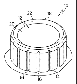
FIGURE 1 is a first perspective view depicting a
first step in a method according to a preferred
embodiment of the invention;
FIGURE 2 is a second perspective view depicting a
second step in the method that is performed according to
the preferred embodiment of the invention; and
FIGURE 3 is a fragmentary diagrammatic view
depicting a portion of an article that is illustrated in
FIGURE 1.
Referring in particular to FIGURE 1, a method
according to a preferred embodiment of the invention


CA 02426788 2003-04-23
WO 02/36284 PCT/EPO1/12581
-5-
includes a step of providing a preform 10 that has a base
12 and a side wall 14. As may be seen in FIGURE 1,
preform 10 is configured so that side wall 14 has a
plurality of axially extending ribs 16 defined therein.
For purposes of this document, the term "ribs" should be
construed as broadly encompassing all forms of axially
extending structure on a container body, cup or preform
that may deviate from the standard cylindrical shape of
the side wall.
As is shown in FIGURE 1, preform 10 is constructed
so that side wall 14 is coextensive with base 12 and
intersects base 12 at a circular rim 18 that represents
the apex ("basemost" dimensional extent) of the preform
10. In the preferred embodiment, base 12 includes a flat
portion 20 that is substantially circular in shape when
viewed from beneath the preform 10, as shown in FIGURE 1.
Flat portion 20 is, as the name implies, substantially
flat or residing substantially within a plane. As may
perhaps best be seen in FIGURE 3, base 12 further
includes a sloped portion 22 that is coextensive with and
joins the flat portion 20 of base 12 to the rim 18.
According to one particularly advantageous feature
of the invention, the flat portion 20 of base 12 is
recessed with respect to the rim 18 by a predetermined
distance D that is sufficient to ensure that enough
material is present in this general area of the preform
10 so that when the preform 10 is processed in a later
forming step into a completed can body of the type having
a recessed or "bump-up" base configuration, as shown in


CA 02426788 2003-04-23
WO 02/36284 PCT/EPO1/12581
-6-
FIGURE 2, the axial ribs 16 will not be drawn into the
rim area 38 of the container body.
FIGURE 2 depicts the completed container body 30 for
a two piece can, which includes a recessed base 32, a
side wall 34 having a plurality of axially extending ribs
36 formed therein and the rim area 38. The recessed base
32 includes, as is typical, a major projection 40 in the
rim area 38 and a number of interior additional annular
projections 42.
In the preferred embodiment of the invention, the
predetermined depth D of the recessed portion is within a
range of about 0.762 mm (0.03 inches) to about 7.62 mm
(0.30 inches). More preferably, depth D is within a range
of about 1.524 mm (0.06 inches) to about 6.35 mm (0.25
inches).
In the preferred embodiment of the invention, the
preform 10 depicted in FIGURE l is formed from a standard
cup in a first redraw operation, and the completed
container body 30 shown in FIGURE 2 is formed from the
preform 10 in a second redraw operation. Alternatively
however, the initial cup itself may also be formed so as
to have a recessed base, so that the formation of the
recessed base is not necessary in the first redraw
operation.

Representative Drawing
A single figure which represents the drawing illustrating the invention.
Administrative Status

For a clearer understanding of the status of the application/patent presented on this page, the site Disclaimer , as well as the definitions for Patent , Administrative Status , Maintenance Fee  and Payment History  should be consulted.

Administrative Status

Title Date
Forecasted Issue Date 2007-10-09
(86) PCT Filing Date 2001-10-25
(87) PCT Publication Date 2002-05-10
(85) National Entry 2003-04-23
Examination Requested 2003-12-15
(45) Issued 2007-10-09
Deemed Expired 2015-10-26

Abandonment History

There is no abandonment history.

Payment History

Fee Type Anniversary Year Due Date Amount Paid Paid Date
Registration of a document - section 124 $100.00 2003-04-23
Application Fee $300.00 2003-04-23
Maintenance Fee - Application - New Act 2 2003-10-27 $100.00 2003-09-22
Request for Examination $400.00 2003-12-15
Maintenance Fee - Application - New Act 3 2004-10-25 $100.00 2004-09-22
Maintenance Fee - Application - New Act 4 2005-10-25 $100.00 2005-09-16
Maintenance Fee - Application - New Act 5 2006-10-25 $200.00 2006-09-20
Final Fee $300.00 2007-07-20
Maintenance Fee - Application - New Act 6 2007-10-25 $200.00 2007-09-17
Maintenance Fee - Patent - New Act 7 2008-10-27 $200.00 2008-09-15
Maintenance Fee - Patent - New Act 8 2009-10-26 $200.00 2009-10-08
Maintenance Fee - Patent - New Act 9 2010-10-25 $200.00 2010-10-14
Maintenance Fee - Patent - New Act 10 2011-10-25 $250.00 2011-10-14
Maintenance Fee - Patent - New Act 11 2012-10-25 $250.00 2012-10-11
Maintenance Fee - Patent - New Act 12 2013-10-25 $250.00 2013-10-14
Owners on Record

Note: Records showing the ownership history in alphabetical order.

Current Owners on Record
CROWN CORK & SEAL TECHNOLOGIES CORPORATION
Past Owners on Record
DERR, BENJAMIN
KIRK, WILLIAM A.
Past Owners that do not appear in the "Owners on Record" listing will appear in other documentation within the application.
Documents

To view selected files, please enter reCAPTCHA code :


To view images, click a link in the Document Description column. To download the documents, select one or more checkboxes in the first column and then click the "Download Selected in PDF format (Zip Archive)" or the "Download Selected as Single PDF" button.

List of published and non-published patent-specific documents on the CPD .

If you have any difficulty accessing content, you can call the Client Service Centre at 1-866-997-1936 or send them an e-mail at CIPO Client Service Centre.


Document
Description 
Date
(yyyy-mm-dd) 
Number of pages   Size of Image (KB) 
Abstract 2003-04-23 2 73
Claims 2003-04-23 2 51
Drawings 2003-04-23 1 22
Description 2003-04-23 6 252
Representative Drawing 2003-04-23 1 7
Cover Page 2003-06-26 1 43
Claims 2006-07-10 2 39
Representative Drawing 2007-09-17 1 9
Cover Page 2007-09-17 1 44
PCT 2003-04-23 9 320
Assignment 2003-04-23 9 375
Fees 2003-09-22 1 34
Prosecution-Amendment 2004-02-09 1 35
Prosecution-Amendment 2003-12-15 1 32
Prosecution-Amendment 2006-01-18 2 45
Prosecution-Amendment 2006-07-10 3 98
Correspondence 2007-07-20 2 50