Note: Descriptions are shown in the official language in which they were submitted.
CA 02426886 2009-01-07
CONNECTION SYSTEM
The invention relates to a connection system with a current bar and a
contact foot and with a clamping element and a bearing bar with an edge,
whereby the clamping element reaches behind the bearing bar edge and fixes the
contact foot at the bearing bar.
This type of connection system, which is known from EPO 554 519 Bl,
for example, is usually part of a protective conductor terminal or a ground
conductor terminal which serves for producing a conductive connection between
one or more electrical conductors and a protective conductor busbar. To that
end,
a conductor bar with conductor terminals and a connection system comprising-a
mounting foot or contact foot, which is connected to said current bar, are
installed
in an insulating housing of the protective conductor series terminal or ground
series terminal. The metallic mounting foot connects the current bar to the
protective conductor busbar, also referred to as a bearing bar or cap bar.
In the known connection system, the contact foot and current bar are
contacted by a fixed mechanical, and therefore permanent, connection, for
instance by means of a weld, solder, or rivet joint between the contact foot
and the
current bar as according to the German utility model DE 77 12 331 U1.
Additional assembly devices are needed in order to produce these permanent
connections, which leads to an unwanted production expenditure in the assembly
of the connection system and thus the assembly of the protective conductor
terminal.
It is thus the object of the invention to simplify a connection system of the
above type with respect to production.
This object is inventively achieved by a connection system with a current bar
and a
contact foot and with a clamping element and a bearing bar with an edge,
whereby the
clamping element reaches behind the bearing bar edge and fixes the contact
foot at the bearing
bar, characterized in that the contact foot is contacted at the current bar by
means of a resilient
clamp connection. The connection between the contact foot and the current bar
of the
connection system is constructed as a resilient clamp connection. In this
context, resilient
clamp connection also encompasses a catch mechanism whose spring action
guarantees not
only a secure mechanical retention or fixing but also a reliable electrical
contact between the
contact foot and the current bar. The clamp connection can be advantageously
unmade.
1
CA 02426886 2009-01-07
The invention is based on the idea that such a connection system can be
simplified with respect to production if the interconnection among its
individual
parts is achieved simply by putting the parts together. In order to ensure
reliable
conductive contact as well as mechanical stability, gaps in the connection
between
the current bar and the contact foot, which may arise as a result of
production
tolerances, for example, should be avoided or at least compensated. Such
compensation can be easily and reliably achieved by placing at least one of
the
relevant parts in the connection under a certain initial mechanical tension.
The resilient clamp connection thus enables easy assembling of the
mounting foot and the current bar without additional assembly devices, and on
the
other hand, it enables reliable contacting of the contact foot to the current
bar; and
therefore makes possible a durable electrical current.
In an expedient development of the connection system, two contact legs
are provided, at least one of which is resilient. According to a first
variant, both
the first contact leg and the second contact leg are formed on the contact
foot,
whereas in a second variant, the first contact leg is formed on the contact
foot, and
the second contact leg is part of the clamping element.
In the first variant, the contact foot consists of a resilient material,
whereby the two contact legs form a V prior to being contacted with the
current
bar. After the contact foot, which comprises the contact legs, has been
connected
to the current bar by the squeezing together of the two contact legs and the
subsequent insertion of the free ends of the legs into receptive recesses or
openings in the current bar, the contact legs in the clamp connection are
under
initial tension as a result of their spring force being exerted on the wall of
the
recess or opening. For purposes of accepting the two contact legs, one current
bar
opening can be provided for each of the free ends, or a common opening can be
provided for both free ends.
In the second variant, the second contact leg extends as part of the
clamping element parallel to the first leg, which is part of the contact foot,
in the
clamp connection to the current bar.
2
CA 02426886 2009-01-07
In either variant, the clamping element can be attached or arranged at the
contact foot in different ways, the connection being either permanent or
detachable. In the first variant, the clamping element is expediently formed
at the
contact foot. The clamping element is then a united or one-piece component of
the contact foot, which makes possible a high degree of pre-production. The
contact foot is then preferably a metallic punched profile part.
In the second variant, the clamping element is expediently a separate part
consisting of resilient material, preferably in the form of a steel clamping
spring
produced from a punch-bent part. In this case, in order to guarantee precise
positioning, the clamping element comprising the second contact leg includes a
recess or holding opening, through which a holding or positioning nose that is
formed at the contact foot reaches when these two individual parts have been
put
together. In the connection to the current bar, the second contact leg - which
is
united with the clamping element in this variant - is under an initial tension
as a
result of the spring force of the clamping element that is exerted on the edge
of'
the recess or opening facing the clamping element. The free end of the leg of
the
clamping element is inserted in the same current bar opening as the free end
of the
(first) contact leg of the contact foot.
Whereas, in the one-piece variant, the spring effect that is required for the
resilient clamp connection is achieved by the two contact legs being moved in
the
direction of one another and contacted with the current bar during the
assembling
process, in the two-piece variant, the end of the clamping element near the
current
bar only is led in the direction of the rigid contact foot, i.e. the first
contact leg.
To that end, in a development of the invention, an abutment is provided at the
contact foot in the form of a camber that is directed toward the clamping
element.
This forms a bending edge for the clamping element during the compressing of
the two contact legs for purposes of generating the initial tension required
in the
clamp connection to the current bar.
Instead of the fixing or receiving opening in the current bar for
guaranteeing reliable contacting of the contact foot to the current bar, this
can also
have collar-type contours which then form the corresponding installation
surfaces
3
CA 02426886 2009-01-07
for the free ends of the contact legs. For a catch connection, recesses or
fixing
openings are expediently provided in the current bar, which openings are
engaged
on the top side of the current bar, which is averted from the contact foot, in
the
region of their edges by catch elements which are formed on the free ends of
the
contact legs. In this current bar contacting mechanism by means of a catch,
one
contact opening (catch opening) can be provided for each contact leg, or one
opening can be provided for both legs.
In either variant, the clamping element is at least partially arc-shaped or
semicircular for purposes of fixing or holding the contact foot at the bearing
bar
with secure contact. This shape makes possible a reliable reach=around at the
edge of the bearing bar with sufficient spring force. The arc-shaped or
semicircular shape forms a clamping leg with a large clamping power at the
free
end of the clamping element on the bearing bar side.
The connection system is a component of a protective conductor terminal
or ground conductor terminal. The connection system is inserted in the
isolating
housing of the protective conductor terminal and positioned there. Internally,
the
current bar is conductively connected to connection devices in the form of
spring
clamps or what are known as cage tension springs for the clamp contacting of
ground conductors or protective conductors. For the clamp contacting, the
protective conductor terminal is snapped onto the bearing bar, usually
together
with other series mounted devices, particularly for the phase conductors of a
three-conductor or four-conductor network.
According to one aspect of the invention there is provided a connection
system comprising:
a current bar;
a bearing bar having a bearing bar edge;
a contact foot having a first contact leg, said contact foot being contacted
at said
current bar in a resilient clamp connection;
a clamping element being separate from said contact foot and having a second
contact leg, said clamping element extending behind said bearing bar edge and
removably fixing said contact foot at said bearing bar; and
one of said first and second contact legs serving as an abutment for and
resiliently
prestressing the other of said first and second contact legs in said resilient
clamp
connection with said current bar.
4
CA 02426886 2009-01-07
According to a further aspect of the invention there is provided a connection
system comprising:
a current bar;
a bearing bar having a bearing bar edge;
a contact foot having a first contact leg and a second contact leg formed
thereon,
said contact foot being contacted at said current bar in a resilient clamp
connection,
and one of said first and second contact legs being deflected towards and
resiliently
prestressing the other of said first and second contact legs in said resilient
clamp
connection with said current bar; and
a clamping element formed on said contact foot, extending behind said bearing
bar
edge and removably fixing said contact foot at said bearing bar.
According to another aspect of the invention there is provided a protective
conductor terminal comprising:
a current bar;
a bearing bar having a bearing bar edge;
a contact foot having a first contact leg, said contact foot being contacted
at said
current bar in a resilient clamp connection;
a clamping element being separate from said contact foot and having a second
contact leg, said clamping element extending behind said bearing bar edge and
removably fixing said contact foot at said bearing bar; and
one of said first and second contact legs serving as an abutment for and
resiliently
prestressing the other of said first and second contact legs in said resilient
clamp
connection with said current bar.
According to yet another aspect of the invention there is provided a
protective
conductor terminal comprising:
a current bar;
a bearing bar having a bearing bar edge;
a contact foot having a first contact leg and a second contact leg formed
thereon,
said contact foot being contacted at said current bar in a resilient clamp
connection,
and one of said first and second contact legs being deflected towards and
resiliently
prestressing the other of said first and second contact legs in said resilient
clamp
connection with said current bar; and
a clamping element formed on said contact foot, extending behind said bearing
bar
edge and removably fixing said contact foot at said bearing bar.
5
CA 02426886 2009-01-07
The advantages of the invention consist specifically in the ability to
assemble the individual parts of the connection system easily by virtue of a
resilient connection in the form of a plug, clamp, or catch connection between
a
current bar and a contact foot of a connection system, with or without a
separate
clamping or spring element. In addition, with few individual parts, a
particularly
high level of pre-production can be achieved for the connection system, and
with
it a protective conductor terminal. By developing the individual parts as plug
elements, a modular connection system, particularly for ground conductor
6
CA 02426886 2009-01-07
terminals, is provided according to a unit assembly system, with which a
number
of different instances can be realized.
Exemplifying embodiments of the invention will now be described with
the aid of a drawing. Shown are:
Fig. 1: perspective representation of a connection system with a contact
foot and a separate clamping spring;
Fig 2: the connection system according to Fig. I in an exploded view;
Fig. 3: a section III from Fig. I with an enlarged view of a resilient single-
hole clamp connection in the region of the current bar;
Fig. 4: perspective view of an alternative embodiment of the connection
system with a clamping element that is formed on the contact foot;
Fig. 5: the connection system according to Fig. 4 in an exploded view;
and
Fig. 6: a section VI from Fig. 4 in an enlarged view with a resilient two-
hole clamp connection in the region of the current bar.
Corresponding parts are provided with identical reference characters in all
Figures.
In a first two-part embodiment - previously referred to as the second
variant - of the inventive connection system 1 according to Figures 1 to 3, a
contact foot or attachment foot 2 and a clamping element 3 are disposed
between
a current bar 4 and a bearing bar 6 as separate parts. The top half of the
contact
foot 2, which is the side nearer the current bar, is constructed as a contact
leg 8,
whereas the second half, the side near the bearing bar, forms a contact nose
10.
The contact foot 2 is a one-piece component, preferably a punched part.
The clamping element 3, which is produced from a bent or rolled sheet
part, is disposed at the contact foot 2. The top half of the clamping element
3, the
side near the current bar, likewise serves as contact leg 12, which is adapted
to the
shape and curve of the contact or attachment foot 2. In the bottom region on
the
bearing bar side, the clamping element 3 comprises an arc-shaped or U-shaped
clamping leg 15, whereby a clamp opening 14 is formed, which leg, in joining
with the bearing bar 6, reaches around, and makes clamping contact with, the
7
CA 02426886 2009-01-07
edge 6a of the bearing bar and the contact nose 10, which abuts said edge, of
the
contact foot 2.
The clamping element 3 has a holding opening and a positioning opening
16a and 16b, respectively, in the form of rectangular through-opening or
recesses
on the current bar side and bearing bar side. Corresponding holding noses 18a
and 18b which are formed at the contact foot 2 reach through these holding
openings 16a and 16b, respectively, so that the clamping element 3 is
positioned
and fixed in place in the assembled condition.
An expediently rectangular fixing or clamping opening 20 is located in the
current bar 4. On the free end, which faces the current bar 6, of the contact
leg 8
of the contact foot 2, a fixing nose 22a is formed, which is inserted into the
clamping opening 20 together with a clamping nose 24 which is realized on the
free end of the contact leg 12 of the clamping element 3. In order to insert
the
two contact legs 8 and 12 into the clamping opening 20, the contact leg 12,
and
with it the clamping nose 24, are pressed in bending direction 25 parallel to
the
bearing bar 6 and the current bar 4.
The bending, which generates initial spring tension, occurs around a
bending edge 25, which is formed by a camber 27 that is formed on the contact
foot 2 in the region of the leg 8 thereof. The camber 27, which is raised in
the
direction of the clamping element 3, thus serves as an abutment or an abutment
cam for the clamping element 3 for purposes of prestressing it when the
contact
leg 8 of the contact foot 2 and the contact leg 12 of the clamping element 3
are
pressed together. This prestressing of the clamping element 3 guarantees a
reliable resilient clamp or catch connection and thus a reliable contacting of
the
contact foot 2 to the current bar 4. The spring deflection of the clamping
nose 24,
and thus of the contact leg 12 of the clamping element 3, which deflection the
resilient clamping element 3 requires for correction, is blocked by the edge
of the
fixing or clamping opening 20, which acts as a stop.
For fixing the contact foot 2 to the bearing bar 6, the U-shaped clamping
leg 15 of the clamping element 3 forms a clamping arm 28, which is located on
the bottom side of the bearing bar 6, the side averted from the contact nose
10.
8
CA 02426886 2009-01-07
By swinging out during the insertion of the bearing bar edge 6a into the
clamping
element opening 14, the clamping arm 28 exerts a clamping pressure on the
bearing bar edge 6a in the clamping pressure direction 30. In order to
guarantee
easy insertion of the bearing bar edge 6a into the clamping element opening
14,
an incline 32 which runs opposite the clamping pressure direction 30 is formed
on
the clamping arm 28 at the free end.
Figure 2 represents relatively clearly the shapes and designs of the contact
foot 2 and the clamping element 12 in the two-part variant. The clamp
contacting
of the contact foot 2 at the bearing bar 6 by means of the separate clamping
element 3 occurs only at one of the two bearing bar edges 6a or 6b, which is
advantageous particularly in view of the small material requirement.
Figure 3 is a detail representation of the clamp connection between the
current bar 4 and the two clamp or contact legs 8 and 12 of the contact foot 2
and
the clamping element 3 in perspective. A cushion-type inwardiy bulging edge of
the fixing or clamping opening 20 is evident. This achieves a precise
positioning
of the free ends of the legs in the form of the fixing nose 22a of the contact
foot 2
and the clamping nose 24 of the clamping element 3, which reach through the
clamping opening 20 in the clamp connection. In addition, the two clamp legs
8,
12 are led close to one another in the direction of pressure 34, forming only
a
small clamp gap 35, whereby the approximately linear contact leg 12 of the
clamping element 3 is pressed to the contact foot 2.
Due to the camber 27 acting as an abutment cam, a certain amount of
pressure is required in order to be able to insert the fixing nose 22a and the
clamping nose 24 into the fixing opening 20. The clamping nose 24 exerts a
clamping pressure on the fixing opening 20 by way of the spring pressure that
is
directed against the direction of pressure 34. This resilient clamp contact
can be
unmade by moving the contact leg 3 further in pressure direction 34, whereby
the
width d of the clamping gap 35 is reduced, and the clamping between the
contact
foot 2, the clamp element 12, and the current bar 4 is released.
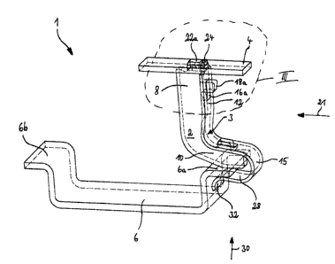
In the one-part embodiment of the connection system 1, which is
represented in Figures 4 to 6 (previously referred to as the first variant ),
the
9
CA 02426886 2009-01-07
contact foot 2' and the clamping element 3' are a one-piece or united molded
part.
In this variant, the clamping element 3' is formed on the contact foot 2' in
the
region of the contact nose 10. This unified contact-clamp element is a punched
profile part, preferably a metallic punched profile part consisting at least
partly of
a copper special alloy. In contrast to the variants according to Figures 1 to
3, in
this variant, both the first contact leg 8' and the second contact leg 12' are
formed
on the contact 2. The two contact legs 8' and 12' extend substantially
parallel to
one another in the clamp connection shown in Figures 4 and 6, whereas the
contact legs 8' and 12' form an approximate V shape in the initial condition
according to Figure 5. Each of the fixing noses 22b and 22c which are formed
on
the first contact leg 8' and the second contact leg 12' reaches through a
respective
fixing opening 20a or 20b in the current bar.4.
The clamping element 3' that is formed on the contact foot 2' in turn forms
an arc-shaped or U-shaped clamping leg 15, which likewise comprises an
inclination 32 on the free end for inserting the bearing bar edge 6a. The
clamping
element 3' in turn exerts a clamping force in the clamping direction 30 upon
the
bearing bar edge 6a, which, analogously to the variant according to the
Figures 1
to 3, also lies between the contact nose 10 of the contact foot 2' and the
clamping
arm 28' of the clamping element 3' in the clamp or catch connection, with the
effect that an isolating housing, which accepts the connection system 1, of a
protective conductor terminal (which is not represented in detail) is held on
or at
the bearing bar 6 in a reliable but detachable fashion. For this reason, the
clamping element 3' exhibits the requisite resilient characteristics based on
its
arch-shaped design.
Fig. 5 represents an insertion gap 38 between the free end of the clamping
ann 28' of the clamping element 3' and the contact nose 10 of the contact foot
2',
whereby this insertion gap 38 is srimalier than the profile thickness of the
bearing
bar edge 6a. With the insertion or pushing of the bearing bar edge 6a along
the
inclination 32' into said gap 38, said gap 38 is enlarged or widened under the
initial tension of the clamping element 3'. In turn, the clamping arm 28
exerts the
requisite holding or fixing pressure on the bearing bar edge 6a in clamping
CA 02426886 2009-01-07
pressure direction 30 based on its resilience. The contact nose 10 of the
contact
foot 2' serves as abutment therein.
Figure 6 represents a detail view of the resilient clamp connection that is
formed in this variant between the two contact legs 8', 12' of the contact
foot 2'
and the current bar 4. The clamp contact is achieved by way of the two fixing
noses 22b and 22c which are formed at the contact legs 8', 12'. For purposes
of
penetrating the two fixing openings 20a and 20b, the two contact legs 8', 12',
which form a V in their resting position, are moved toward one another with
their
fixing noses 22b and 22c, whereby.the two fixing noses 22b and 22c are pressed
in bending directions 40 and 42, respectively. The pressure of the two contact
legs 8' and 12' to correct themselves against their respective bending
directions 40
and 42 gives rise to the resilient clamp contact between the contact foot 2'
and the
current bar 4. In the clamp connection, the two contact legs 8' and 2' are
parallel
to one another.
This resilient clamp contact can also be unmade by moving the two
contact legs 8' or 12' in their respective bending directions 40, 42 until the
contact
between the fixing noses 22b, 22c and the corresponding fixing openings 20a
and
20b is lost. The two contact legs 8' and 12' can then be withdrawn from the
corresponding fixing openings 20a and 20b, whereby the clamping between the
contact foot 2' and the current bar 4 is released.
11