Note: Descriptions are shown in the official language in which they were submitted.
CA 02427145 2003-04-28
WO 02/36189 PCT/EPO1/12107
Medicament dispenser
3echnicai Meld
The present invention relates to a medicament dispenser fior dispensing
medicament. The invention particularly relates to an inhalation device for use
in
dispensing medicament.
~aciCgr~tand to the invention
The use of inhalation devices in the administration of medicaments, for
example
in bronchodilation therapy is well known. Such devices generally comprise a
body or housing within which a medicament carrier is located. Known
inhalation devices include those in which the medicament carrier is a blister
strip
containing a number ofi discrete doses of powdered medicament. Such devices
usually contain a mechanism for accessing these doses, usually comprising
either piercing means or means to peel the lid sheet away from the base sheet.
The powdered medicament can then be accessed and inhaled.
It is an object of the present invention to provide a medicament dispenser
(e.g.
an inhalation device) which is refillable by insertion of a replacement
cassette
containing a medicament carrier. The cassette may be replaced when the
medicament carrier is empty. The dispenser is therefore 'environmentally
friendly' as the majority of the dispenser may be retained and is not
disposable.
It also allows the retained part ofi the dispenser to be fitted with
additional
features such as electronics which may not be cost effective on a completely
disposable dispenser.
It is a further object of the present invention that the cassette may be
easily
removed and that a new replacement cassette can be easily inserted. It is also
desirable that the operation of the medicament dispenser is straightforward
and
1
CA 02427145 2003-04-28
WO 02/36189 PCT/EPO1/12107
non-complex and in particular that the number of separate steps involved in
preparing the dispenser for use is minimised. It is further desirable that in
exceptional circumstanbes the cassette may be used on its own as a standalone
medicament delivery system. This is especially relevant where the dispenser is
designed for use in the delivery of medicament in emergency or rescue
situations (e.g. asthma attacks) where simplicity and ease of use is
paramount.
When not in use it is desirable from a hygiene standpoint that the dispensing
part
(e.g. an outlet, perhaps in the form of a mouthpiece) is provided with some
kind
of protective cover. The cover desirably acts both to prevent build-up of dirt
on
the dispensing part and to prevent ingress of dirt into the body of the
dispenser
through the dispensing part, which might then be subject to ingress by a
patient.
It is also desirable that the cover is in some way attached or mounted to the
dispenser to minimise the risk that the cover is misplaced or lost. It is
therefore a
further object of the present invention for the body of the dispenser to act
as a
cover for the dispensing part when the dispenser is in storage and that the
cassette is movable relative to the body to enable the dispensing part to be
uncovered for use by the patient.
It is a further object of the invention to provide a medicament dispenser
suitable
for use with a large number of discrete doses but which is of an acceptable
size
for use by patients.
Summary of the invention
According to one aspect of the present invention there is provided a
medicament
dispenser for dispensing medicament comprising: a body; a holder, shaped to
fit
within said body and movable relative to the body; and receivable by said
holder,
a cassette containing a medicament carrier, wherein movement of the holder
relative to the body results in movement of the cassette between a first
position
and a second position such that the cassette is reversibly removable from the
holder when the cassette is in the second position.
2
CA 02427145 2003-04-28
WO 02/36189 PCT/EPO1/12107
Preferably the first position comprises a dispensing position. Preferably the
second position comprises a non-dispensing position. The cassette is therefore
only removable from the holder when the cassette is in the non-dispensing
position.
Suitably, the cassette wholly encloses the medicament carrier and acts as a
protective shell therefor.
The cassette may have any suitable form including for example, an essentially
flat disc form. The holder and body may also have any suitable form.
Embodiments are envisaged in which the cassette is receiving as a top-load,
bottom-load or side-load.
Suitably the holder and body include atfiachment means to attach the holder to
the body. In one aspect, said attachment means comprises a snap-fit
mechanism. Suitably, the snap-fit mechanism comprises a pin and hole system.
In one aspect, the holder is pivotally movable relative to the body. In
another
aspect, the holder is rotationally movable relative to the body. In a further
aspect,
the holder is slidably movable relative to the body.
Suitably, the holder additionally comprises one or more stops to limit
movement
of the holder relative to the body. In one aspect, two distinct stop positions
are
defined corresponding to the dispensing and non-dispensing positions
respectively.
Where the holder is rotationally movable relative to the body, the one or more
stops suitably limit movement of the holder relative to the body to no more
than
about 180° rotational path. In one preferred aspect, the dispensing and
non
dispensing positions are separated by about 180° rotation, and
corresponding
stop positions are defined.
Suitably, the one or more stops abut against the edge of the body at defined
points) when it is moved. At these points the holder is suitably designed to
click
3
CA 02427145 2003-04-28
WO 02/36189 PCT/EPO1/12107
into a stop position. In aspects, in the dispensing position the stop abuts or
click-
engages one body edge, and in the non-dispensing position the stop abuts or
click-engages another body edge.
Where the holder is rotationally movable relative to the body, the one or more
stops suitably limit movement of the holder relative to the body to no more
than
about 180° rotational path.
Suitably, the holder additionally comprises a retainer for retaining the
cassette
therewithin. In one aspect, the retainer comprises a catch. The catch may for
example, comprise a sprung pin which fits into a hole or an integral catch
which
deforms when pressed allowing removal of the cassette. Preferably, the
retainer
is child resistant. Child resistance may be realised by having a system which
forces the user to perform two actions at once to remove the cassette. Other
features of the retainer may include shock or impact resistance, the ability
to lock
the catch and orientation features to ensure that the cassette can only be
inserted one way. The retainer should also be easy to manufacture and
assemble, be robust, be composed of a minimal number of components and
intrude minimally info the space into which the cassette is inserted.
Suitably, the holder includes a guide for guiding the insertion of the
cassette into
the holder. Preferably said guide comprise guide rails. Alternatively the
guide
comprises grooves, indentations or other shaping or surface details to define
a
'lock and key' relationship between the holder and the cassette. Colour
guides,
arrows and any other surface markings may also be employed.
Suitably, the cassette additionally comprises an indexer (e.g. an indexing
lever)
for indexing the medicament carrier. In one aspect, the indexing lever has a
finger tab located outside the body of the cassette. The rest of the indexing
lever
is located within the cassette. The indexing lever may have teeth at its tail
end
andlor teeth along ifs mid portion. Suitably, the indexing lever is operable
(e.g.
for emergency use) even when the cassette is not inserted within the holder.
4
CA 02427145 2003-04-28
WO 02/36189 PCT/EPO1/12107
Suitably, the cassette additionally comprises a dispensing outlet. The
dispensing
outlet may have any suitable form ranging from a simple orifice to a shaped
passage (e.g. cone or tube) to a mouthpiece or nozzle. The presence of a
dispensing outlet as part of the cassette itself is beneficial in that it
enables the
cassette to be used in emergencies as a functioning inhaler, even when the
cassette is separate from its holder/body.
In aspects, the dispensing outlet is extendable. In one aspect, the dispensing
outlet extends as the cassette and holder are moved from the non-dispensing
position to the dispensing position.
Alternatively, the dispensing outlet is retractable (e.g. it is reversibly
retractable
from the cassette). In one aspect, the dispensing outlet retracts as the
cassette
and holder are moved from the dispensing position to the non-dispensing
position.
In one aspect, the dispensing is telescopic in form. In anofiher aspect, the
dispensing outlet is fixed.
The medicament dispenser may also be designed for nasal inhalation of
medicament and the dispensing outlet may therefore incorporate a nozzle
('nosepiece') as an alternative to a mouthpiece.
Suitably, the body covers the dispensing outlet and indexer when the cassette
is
in the non-dispensing position. This avoids the need for a separate cover and
protects the mouthpiece from the ingress of dirt and contaminants during
storage.
Suitably, the cassette is shaped to prevent its incorrect insertion into the
holder.
In one aspect, the cassette additionally comprises a raised portion to fit
against
the holder. The raised portion is located at the opposite end of the cassette
to
the mouthpiece and indexing lever and prevents the incorrect insertion of the
cassette into the holder since it is too wide to fit into the holder. The
raised
portion is shaped such that it fits against a cut away part of the holder.
s
CA 02427145 2003-04-28
WO 02/36189 PCT/EPO1/12107
Preferably, the raised portion includes a section which is raised to define a
grip
portion.
The medicament carrier may have any suitable shape or form for the carrying of
medicament in a variety of forms including dry powder, granule, aerosol
suspension, solution including aqueous solution, capsule, nebuie, pellet and
tablet carrier form.
In aspects, the medicament carrier respectively comprises a capsule; a tablet
carrier; an aqueous container; an aerosol container; and a dry powder
container.
In one aspect, the medicament carrier comprises a container for a reservoir of
dry powder. In this aspect the cassette additionally requires a meter for
metering
a dose of medicament. In one aspect, the dose meter defines a metering recess,
wherein the metering recess communicates with the medicament container to
receive a metered volume of powder when the cassette is in the non-dispensing
position and the metering recess communicates with the dispensing outlet to
allow passage of the metered volume of powder thereto in the dispensing
position.
In another aspect, the medicament carrier comprises an elongate carrier
(either
linearly or angularly elongate) which may in aspects, be preloaded with
medicament. The elongate carrier can take a variety of forms but preferably is
a
tape, web, belt, strip or cord. The powdered medicament may be retained on the
carrier by electrostatic attraction, Van der Waals forces, physical
attraction,
mechanical binding, printing e.g. inkjet printing of the dose onto the
carrier,
wedging or by a cover layer or an overlying layer of the same carrier when the
carrier is wound etc. One or more surfaces of the carrier and optionally the
interior of the carrier may be configured to assist in retaining the particles
of
powder.
In one aspect, the medicament carrier comprises a blister pack, suitably in
elongate form. Preferably, the medicament carrier comprises a blister strip.
Preferably said blister strip comprises an elongated strip formed from a base
6
CA 02427145 2003-04-28
WO 02/36189 PCT/EPO1/12107
sheet having a plurality of recesses spaced along its length and a lid sheet
peelably sealed in superposed relationship thereto to define a plurality of
blisters,
each having therein inhalable medicament in powder form. Alternatively, the
blisters may contain a tablet or an aqueous solution or suspension.
Suitably, the recesses are capsule shaped. In one aspect, the recesses are
shaped for receipt by a gear or drive mechanism of the cassette. Thus, the
recesses may shaped in the profile of gear teeth or in the profile of belt
drive
teeth. Optionally the lid sheet may contain perforations across its width
spaced
along the strip to allow the lid sheet to concertina ~Nhen it has passed
through the
lid driving means. The lid sheet and/or base sheet may also optionally contain
apertures or holes formed on one or both edges to fit into a sprocl~et.
Suitably, the cassette additionally comprises an internal mechanism for acting
on
the medicament carrier there within. In one aspect, the internal mechanism
comprises an indexer for indexing the medicament carrier. In another aspect,
the
internal mechanism comprises a mover for moving the medicament carrier. In a
further aspect, the internal mechanism comprises access means for accessing
the medicament carrier (and hence medicament associated therewith or
contained there within).
Suitably, the internal mechanism of the cassette is provided with means for
engaging an externally located drive mechanism (e.g. located in the body or
holder) such that it may be driven by said externally located drive.
Suitably, the body or holder additionally comprises a drive mechanism for
driving
at least part of the internal mechanism of the cassette. The drive mechanism
is
in one aspect, a manual drive (e.g. actuable by a finger or thumb movement).
In
another aspect, the drive may be a powered (e.g. motor) drive, as described
hereinafter, which is located in the body or holder.
In one aspect, the cassette comprises an (e.g. externally protruding) indexing
lever which co-operates with the internal mechanism for accessing the
medicament carrier, and may be used without the body or holder if necessary in
7
CA 02427145 2003-04-28
WO 02/36189 PCT/EPO1/12107
the event that mechanical or electronic breakdown of the components of the
body and holder should occur, or for emergency use of the cassette as a
makeshift, but functioning dispenser.
Preferably, the internal mechanism comprises:
a) an opening station for receiving a medicament carrier of the cassette, said
medicament carrier having plural individual medicament containers;
b) an indexer for indexing an individual medicament container of the
medicament
carrier for receipt by said opening station;
c) an opener for opening said indexed individual medicament container; and
d) a dispensing outlet, positioned to communicate with said opened container.
Suitably, the medicament carrier comprises a blister strip accessible by a
peeling
action. The peelable blister strip comprises a base sheet and lid sheet which
may be peeled apart to uncover a pocket in the base sheet.
Suitably, the opener comprises peeling means positioned to engage a base
sheet and a lid sheet of a peelable blister strip which has been received in
said
opening station for peeling apart such a base sheet and lid sheet. In one
aspect,
the peeling means includes lid driving means for pulling apart a lid sheet and
a
base sheet of a container that has been received at said opening station.
In an inhalation device aspect, the dispensing outlet is in the form of a
mouthpiece through which a user can inhale to access the medicament in the
opened container.
Suitably, the indexer comprises a rotatabie index wheel having a recesses
therein, said index wheel being engageable with a medicament carrier in use
with said medicament dispenser such that said recesses each receive a
8
CA 02427145 2003-04-28
WO 02/36189 PCT/EPO1/12107
respective pocket of the base sheet of a medicament carrier in use with said
medicament dispenser.
Suitably, the rotatable index wheel additionally comprises a series of
indentations located at its base and spaced in between the recesses.
Suitably, the indexer additionally comprises an interlock coupling to couple
movement of the lever to the index wheel. The interlock coupling reversibly
locks the index wheel in place. Preferably, the interlock couplirig comprises
a
foot portion having a toe and a heel, and a tail section. Preferably, the
interlock
coupling is pivotally mountable to the cassette at its foot portion.
Preferably, the
toe fits into one of the indentations on the rotatable index wheel.
Preferably, the
heel is finable into the teeth on the lever to lock the lever in place after
it has
been actuated by the patient. Preferably, the interlock coupling is sprung to
bias
it towards location of the toe in one of the indentations.
Alternatively, the indexer comprises a gear and sprocket wherein teeth on the
wheel fit into apertures or holes formed on one or both edges of the blister
strip.
The mechanism therefore resembles that of photographic film being advanced
through a camera.
Alternatively, the indexer comprises a plurality of recesses located on the
tail end
of the indexing lever. The recesses are shaped and sized to engage the pockets
in the blister strip. Movement of the lever by the patient indexes the strip
by one
pocket. When the lever is then returned to its rest position the strip is
disengaged and will reengage the strip one pocket further along. This indexer
has the advantage that it only requires an indexing lever- additional
components
are not needed.
In one aspect, the indexer comprises an index ratchet which is moveable
between a locked position whereby said ratchet engages a pocket on said
medicament carrier and prevents further peeling thereof, and a release
position
allowing free movement of said medicament carrier, and actuation of said
medicament dispenser actuates the lid driving means of the opener to release
9
CA 02427145 2003-04-28
WO 02/36189 PCT/EPO1/12107
said index ratchet from said medicament carrier to allow peeling thereof. In
this
aspect, the lid driving means draws the medicament carrier through the
internal
accessing mechanism. The indexer stabilises and prevents further movement of
the medicament carrier after the required dose of medicament has been
dispensed.
Suitably, said index ratchet is pivotally mounted on said dispenser.
Suitably, the medicament dispenser further comprises an indexing lever for
actuating said dispenser. Typically, said indexing lever comprises cam means
for moving said index ratchet between locked and release positions, such that
actuation of said lever from a stop position releases said medicament carrier
for
peeling thereof. Typically, said indexing lever comprises a lever ratchet for
engaging said lid driving means.
Suitably, said lid driving means comprises an index gear and a drive gear
which
are interconnected so that the rotation of one correlates with the rotation of
the
other.
Alternatively, the indexer comprises an electronic drive system wherein the
strip
is driven by a motor. The electronic drive system additionally comprises a
mechanical clamp to clamp the strip.
Suitably, said lid driving means comprises a wheel on which the lid sheet is
wound up.
Typically, said lid sheet wheel has an effective winding surface, the diameter
of
which increases after every use of the dispenser as the lid sheet winds around
the wheel.
In order to ensure that the same dose is dispensed every time, that is, only
one
medicament pocket is opened for every actuation of the dispenser, the
dispenser
may further comprise a lever stop means to limit the extent of movement of
said
index lever and thereby said lid driving means, in order to control the length
of
to
CA 02427145 2003-04-28
WO 02/36189 PCT/EPO1/12107
medicament carrier peeled by said peeling means. Hence, the medicament
carrier is indexed by the same amount each time and a uniform, consistent dose
is always dispensed.
The dispenser may further comprise compensating means positioned between
said opening station and said lid sheet wheel for reducing the length of said
lid
sheet therebetween to compensate for any increase in the diameter of the
effective winding surface of the lid driving means during use of the
dispenser.
Typically, the compensating means takes the form of a flexible member. The
flexible member may take the form of a flexible elongate arm about which the
lid
sheet is fed. The arm may flex inwards as tension in the lid sheet increases,
and
thus shorten the length of lid sheet between the opening station and the lid
driving means.
Suitably, the compensating means takes the form of a spring which reduces in
length as tension increase in the lid sheet between the opening station and
the
lid driving means. Typically a piston head is mounted on one end of the spring
about which the lid sheet is fed. The other end of the spring may be fixed. As
tension in the lid sheet increases the piston is driven down onto the spring.
Suitably, the compensating means takes the form of a sprung-loaded tensioner.
Suitably, the flexible member is resilient so that on removal of tension from
the
lid sheet, the flexible member will return to its rest position. Thus, the
internal
mechanism can be reloaded with a new medicament carrier after the used
carrier is removed.
Alternatively, or in addition, the dispenser may comprise a clutch means to
adjust for any increase in the diameter of the effective winding surface of
the lid
driving means during use of the dispenser. In one aspect, the clutch means
communicates with the indexing means and the lid driving means, and
comprises a gearing surface defining plural gear engagement positions; and
plural gear teeth for engaging said plural gear engagement positions, wherein
11
CA 02427145 2003-04-28
WO 02/36189 PCT/EPO1/12107
the plural gear teeth are arranged such that at any one time only a single
gear
tooth engages a single gear engagement position.
It will be appreciated that, in use, the clutch means acts to compensate for
the
increase in diameter of said effective winding surface of the lid driving
means.
The clutch means allows for slippage when the tension in the lid sheet is
greater
than the force required to peel apart the lid sheet and the base sheet.
It will be appreciated that in total, the clutch means effectively defines a
number
of individual gear positions which is greater than the number of gear
engagement positions. This is therefore advantageous over a traditional
slipping
clutch arrangement comprising intermeshing gear wheels, where the effective
number of individual gear positions defined is either equal to, or no more
than,
the number of gear engagement positions defined by one of the gear wheels.
The clutch means herein is also typically more compact than traditional
slipping
clutch arrangements e.g. because it enables smaller gearing surfaces to be
employed.
In a preferred aspect, the gearing surface and plural gear teeth are arranged
such that the number of individual gear positions defined is equal to the
number
of gear engagement positions multiplied by the number of gear teeth. In one
example, if the gearing surface defines 60 gear engagement positions and there
are 6 gear teeth, then up to 360 individual gear positions are definable (e.g.
1 °
resolution on a rotating gear system).
Suitably, the gearing surface defines from 20 to 100, preferably from 40 to 80
gear engagement positions. Suitably, the number of gear teeth is from 2 to 20,
preferably from 3 to 10.
In one aspect, the gear engagement positions are equally spaced (e.g..
equidistantly spaced) and the gear teeth are offset (e.g: non-equidistantly
spaced) relative thereto. Such offset arrangement maximises the number of
12
CA 02427145 2003-04-28
WO 02/36189 PCT/EPO1/12107
effective individual gear positions which are capable of definition. An
example of
this aspect, is a Vernier spring arrangement.
In another aspect, the gear engagement positions are also equally spaced (e.g.
equidistantly spaced) and the gear teeth are located on a wobbling element
capable of wobbling the gear teeth to plural offset (e.g. non-equidistantly
spaced)
positions. Such a wobbling offset arrangement also maximises the number of
effective individual gear positions which are capable of being defined. An
example of this aspect, is the wobbling wheel arrangement described herein.
In aspects, the clutch means is non-integral with either of the lid driving
means or
fihe indexing means, but forms a separate interconnecting component.
Suitably, the gearing surface comprises a gear wheel. As used herein, the term
gear wheel encompasses, for example, a wheel, spindle or spool.
Suitably, the gear teeth may be arranged to be in ratchet form (i.e. enabling
movement in one direction only).
Suitably, the gearing surface and gear teeth are in biased (e.g. sprung)
engagement.
In one aspect, the lid driving means comprise a wheel on which the lid sheet
is
wound up. Suitably, said wheel has a winding surface which decreases in
diameter when tension in the lid sheet increases. Suitably, the wheel
comprises
a plurality of resiliently flexible arms each extending therefrom at an angle
with
respect to a radius. The leading end of the lid sheet is looped over one of
said
resiliently flexible arms to secure the !id sheet to the wheel initially.
In another aspect, the lid driving means comprise a mangle. The lid sheet
passes through two rotating wheels which act as a mangle and is gripped at the
point of contact with the wheels. The used portion of the lid sheet is
collected in
a chamber after it has passed through the mangle.
13
CA 02427145 2003-04-28
WO 02/36189 PCT/EPO1/12107
In another aspect, the lid driving means comprise a roller. Suitably, the
roller is
composed of a polymeric rubber and is positioned next to a guide wall.
Suitably,
the roller has a smooth surface. Alternatively, the roller has a knurled
surface.
The roller grips the lid sheet as it passes from the point at which it is
separated
from the base sheet through the space between the roller and the guide wall
and
the used portion of the lid sheet is then collected in a chamber. The roller
has
the advantage over the mangle described above in that a greater degree of
contact between the roller wheel and the lid sheet occurs- the lid sheet is
squeezed through the roller and may pass around about 1/3 of the roller wheel.
This provides a higher level of grip and pulling force than with a mangle. The
force required to turn the roller is constant throughout the use of the device
and
does not vary according to how much of the lid sheet has been peeled away
from the base sheet. This is in contrast to the wheel described above where
the
forces required to turn the wheel may vary due to the tact that the lid sheet
is
wound around the wheel. The lid sheet is not wound around the roller. The
roller also has the advantage that the lid sheet does not have to be looped
around or fixed to the roller before use of the device, therefore simplifying
assembly of the device and reducing costs.
In a further aspect, the lid driving means comprise a lid spool. The lid spool
comprises a toothed wheel with a central upward cylindrical projection on
which
the iid sheet may be wound when it has been separated from the base sheet.
The lid spool has teeth around its base which fit into teeth on the lever. The
lid
spool is therefore driven by the movement of the indexing lever and the lid
sheet
is pulled away from the base sheet and wound onto the lid spool, causing the
rotatable indexing wheel to turn and index the base strip by one dose. The
interlock coupling, as described above, is moved along the base of the
rotatable
indexing wheel until it fits into the next base recess. The positioning of the
interlock coupling in this recess limits the movement of the lid spool to the
distance between two pockets on the base sheet and therefore prevents the
amount of iid sheet which is wound around the lid spool from increasing as the
diameter of the (id spool is increased.
14
CA 02427145 2003-04-28
WO 02/36189 PCT/EPO1/12107
In a further aspect, the lid driving means comprise a spiked wheel. As the
spiked wheel turns, the iid sheet is pulled over it and the spikes perforate
parts of
the lid sheet to improve the grip on the lid sheet. The lid sheet then passes
out
into a chamber where it collects.
In a further aspect, the lid driving means comprise a clamp system. The clamp
system comprises at least one angled spring which is pivotable at one end and
grips the lid sheet at the other end. The clamp system is moved in the
direction
that the lid sheet is to be pulled and grips the lid sheet, pulling it and
therefore
peeling it away from the base sheet. The clamp system is then moved back to
its rest position. This results in the spring pivoting and clamping the lid
sheet,
therefore preventing the lid sheet from being further peeled from the base
sheet.
Suitably, the lid driving means is operable by an electronic drive system. The
electronic drive system may also be used in conjunction with a mechanical
drive
system.
Suitably, the electronic drive system is located in either the body or the
holder
part and the cassette comprises the minimum number of component (i.e. internal
mechanism) parts. In embodiments, the body/holder including the electronic
drive system is designed to be retained by the user and the cassette is sold
as a
refill/reload component which is discarded after use. By locating the
electronic
drive system in the body/holder, the amount of electronic components which are
discarded is minimised.
The electronic drive system typically comprises a motor, preferably an
electrically-powered motor. The motor may provide linear or rotary drive, but
in
general, rotary motors are most suitable. The motor may for example, comprise
a DC electric motor, a piezoelectric (PZ) motor, an ultrasonic motor, a
solenoid
motor or a linear motor. Preferably, the electronic drive system comprises a
DC
motor, a PZ motor or an ultrasonic motor.
The use of ultrasonic motors is particularly preferred since they offer
advantages
over conventional motors in terms of weight, size, noise, cost and torque
is
CA 02427145 2003-04-28
WO 02/36189 PCT/EPO1/12107
generated. Ultrasonic motors are well known in the art and are commercially
available (e.g. BMSTU Technological Cooperation Centre Ltd, Moscow, Russia;
Shinsei Corporation, Tokyo, Japan).
Ultrasonic motors do not use coils or magnets but comprise a piezo-electric
ceramic stator which drives a coupled rotor. The stator generates ultrasonic
vibrations which in turn causes rotation of the rotor. While regular DC motors
are
characterised by high speed and low torque, requiring reduction gearing to
increase torque, ultrasonic motors attain low speed and high torque, thus
eliminating the need for reduction gearing. Furthermore, these motors are
lightweight and compact, lacking coils and magnets, and are noiseless as the
ultrasonic frequencies used are not audible to the human ear.
Suifiably, the dispenser further comprises actuating means for actuating said
electronic drive system. Said actuating means may take the form of a switch,
push-button, or lever.
In another aspect, the used portion of the lid sheet may be passed around
rollers
and fed back onto the used portion of the base sheet after the medicament has
been accessed to join back onto the base sheet. The lid sheet may be coated
with a sticky substance to aid resealing. The use of this mechanism saves
space as the used portions of the blister strip will be collected in the same
area.
In a further aspect, the coil comprising the unused blister strip may be
surrounded by a constant force spring. Alternatively the coil comprising the
unused blister strip may be surrounded by an elastomeric band or band
comprising a contractible material. The constant force spring, elastomeric
band
or band comprising a contractible material contracts as the coil reduces in
size.
Suitably, the peeling means additionally comprise a guide for guiding the lid
sheet and base sheet along separate paths at the opening station. The lid
sheet
is passed around the guide portion onto the lid driving means.
Suitably, the guide comprises a structure fixed in position in the cassette.
16
CA 02427145 2003-04-28
WO 02/36189 PCT/EPO1/12107
Alternatively, the guide comprises a roller mechanism. The lid sheet is fed
over
the rollers onto the lid driving means.
Suitably, the cassette comprises a first chamber for holding the medicament
carrier when charged with medicament and a second chamber to receive the
medicament carrier after release of medicament therefrom. Where the
medicament carrier is in multi-dose form, it may feed from the first chamber
into
the second chamber by way of the opening (or access) station. Thus, in use
that
part of the medicament carrier which is charged with medicament is held in the
first chamber and that part which is empty (i.e. from which medicament has
been
discharged or otherwise released) is in the second chamber. In one aspect, the
first chamber initially houses a charged elongate blister strip and the second
chamber receives the used portion of the base sheet after it has been indexed
around the index wheel and separated from the lid sheet.
Suitably, the first chamber and second chamber are separated by a waft.
Suitably, the wall is movable to adjust the size of the first and second
chambers.
Suitably, the wall is pivotally mountable e.g. the wall is mountable on a pin
fixed
into the cassette. Alternatively, the wall is slidably mountable.
Suitably, the wall additionally comprises at least one brush located along its
top
or bottom side which brush against the top and bottom surfaces of the inside
of
the cassette. The brushes may act to close off the chamber from the rest of
the
body of the cassette and to prevent any loose powder from entering the rest of
the cassette. Loose powder may enter the chambers from the used portion of
the blister strip if the patient indexes the strip by pressing the lever when
they do
not intend to take a dose or when they fail to inhale all the powder.
Alternatively, the wall additionally comprises at least one flexible seal
portion
located along its top or bottom side. The seal may act in the same way as the
brushes described above and seal off the chamber from the rest of the body.
17
CA 02427145 2003-04-28
WO 02/36189 PCT/EPO1/12107
Alternatively, the wall is flexibly movable to adjust the size of the first
and second
chambers.
Alternatively, the second chamber is expandable to create space for the
growing
coil of the used portion of the base sheet.
Suitably, the cassette further comprises a third chamber to receive the used
portion of the lid sheet and a fourth chamber which houses the index wheel.
The
fourth chamber communicates via a slit, which in turn extends upwardly within
a
dispensing outlet and communicates with air inlets.
Suitably the internal mechanism additionally comprises a crushing wheel to
crush the blister pockets after the medicament has been removed from them.
The crushing wheel therefore reduces the space, which the used portion of the
base sheet takes up.
Suitably, at least a portion of the holder and body are shaped for ease of
grip by
the user. Suitably, operation of the medicament dispenser may be performed
with one hand.
Suitably, the medicament dispenser comprises an actuation or dose counter for
counting the number of actuations of the indexing lever or releases of dose
from
the cassette. The dose counter may count the number of doses left to be taken
or the number of doses taken. Suitably, the dose counter is electronic or
mechanical.
In one aspect, the dose counter is located within the cassette. Alternatively,
the
dose counter is external to the cassette.
In one aspect, the medicament carrier (e.g. a blister strip) has printed
numbers
on it corresponding to the doses in the pockets. Suitably, the printed numbers
are visible through a window in the cassette.
is
CA 02427145 2003-04-28
WO 02/36189 PCT/EPO1/12107
Suitably, the medicament dispenser additionally comprises an electronic data
management system. The electronic data management system has input/output
capability and comprises a memory for storage of data; a microprocessor for
performing operations on said data; and a transmitter for transmitting a
signal
relating to the data or the outcome of an operation on the data.
Suitably, the electronic data management system is arranged to be responsive
to or activated by the voice of a user. Thus, for example the system may be
switched on or off in response to a voice command.
The electronic data management system may be integral with the body.
Alternatively, the electronic data management system forms part of a base unit
which is reversibly associable with the body.
15 Suitably, the medicament dispenser additionally comprises a data input
system
for user input of data to the electronic data management system. Preferably,
the
data input system comprises a man machine interface (MMI) preferably selected
from a keypad, voice recognition interface, graphical user interface (GUI) or
biometrics interface.
Energy may be conserved by a variety of means to enable the device to operate
for longer on a given source of energy, such as a battery. Energy conservation
or saving methods have additional advantages in terms of reducing the size
requirements of the power source (e.g. battery) and thus the weight and
portability of the medicament dispenser.
A variety of energy saving methods is available which generally involve
reducing
power consumption. One such method is to use a clock or timer circuit to
switch
the power on and off at regular or predetermined intervals. In another method
the system can selectively switch on/off specific electronic devices, such as
visual display units or sensors, in order to power these devices only when
they
are required to perform a particular sequence of events. Thus different
electronic devices may be switched on and off at varying intervals and for
varying periods under control of the system. The power sequencing system may
19
CA 02427145 2003-04-28
WO 02/36189 PCT/EPO1/12107
also respond to a sensor, such as a motion or breath sensor, which is
acfiivated
on use of the device.
Low power or "micropower" components should be used within the electronics
where possible and if a high power device is required for a parfiicular
function this
should be put into a low power standby mode or switched off when not required.
Similar considerations apply in the selection of transducers. Operation at low
voltage is desirable since power dissipation generally increases with voltage.
For low power digital applications complementary metal oxide semi-conductor
(CMOS) devices are generally preferred and these may be specially selected by
screening for low quiescent currents. Clock speeds of processors and other
logic circuits should be reduced to the minimum required for computational
throughput as power consumption increases with frequency. Supply voltages
should also be kept at minimal values consistent with reliable operation
because
power dissipation in charging interns! capacitance's during switching is
proportional to the square of the voltage. Where possible, supply voltages
should be approximately fihe same throughout the circuit to prevent current
flowing through input protection circuits. Logic inputs should not be left
floating
and circuits should be arranged so that power consumption is minimised in the
most usual logic output state. Slow logic transifiions are undesirable because
they can result in relatively large class-A currents flowing. Resistors may be
incorporated in the power supply to individual devices in order to minimise
current in the event of failure.
In some control applications, devices that switch between on and off states
are
preferred to those that allow analog (e.g. linear) control because less power
is
dissipated in low resistance on states and low current off states. Where
linear
components are used (e.g. certain types of voltage regulators) then types with
low quiescent currents should be selected. In some circuit configurations it
is
preferable to use appropriate reactive components (i.e. inductors and
capacitors)
to reduce power dissipation in resistive components.
Suitably, the system additionally comprises a visual display unit for display
of
data from the elecfironic data management system to the user. The display may
CA 02427145 2003-04-28
WO 02/36189 PCT/EPO1/12107
for example, comprise a screen such as an LED or LCD screen. More
preferably the visual display unit is associable with the body of the
medicament
dispenser.
Suitably, the medicament dispenser additionally comprises a datalink for
linking
to a local data store to enable communication of data between the local data
store and the electronic data management system. The datastore may also
comprise data management, data analysis and data communication capability.
The datastore may itself form part of a portable device (e.g. a handheld
device)
or it may be sized and shaped to be accommodated within the patient's home.
The datastore may also comprise a physical storage area for storage of
replacement cassettes. The datastore may further comprise a system for
refilling medicament from a reservoir of medicament product stored
therewithin.
The datastore may further comprise an electrical recharging system for
recharging any electrical energy store on the medicament dispenser,
particularly
a battery recharging system.
The datalink may for example enable linking with a docking station, a personal
computer, a network computer system or a set-top box by any suitable method
including a hard-wired link, an infra red link or any other suitable wireless
communications link.
Suitably, the medicament dispenser additionally comprises an actuation
detector
for detecting actuation of the dispensing mechanism wherein said actuation
detector transmits actuation data to the electronic data management system.
The medicament dispenser may additionally comprise a safety mechanism to
prevent unintended multiple actuations of the dispensing mechanism. The
patient is thereby protected from inadvertently receiving multiple doses of
medicament in a situation where they take a number of short rapid breaths.
More preferably, the safety mechanism imposes a time delay between
successive actuations of the release means. The time delay is typically of the
order of from three to thirty seconds.
21
CA 02427145 2003-04-28
WO 02/36189 PCT/EPO1/12107
Suitably, the medicament dispenser additionally comprises a release detector
for
detecting release of medicament from the cassette, wherein said release
detector transmits release data to the electronic data management system.
Suitably, the medicament dispenser additionally comprises a shake detector for
detecting shaking of the medicament container (e.g. prior to actuation of the
dispensing mechanism), wherein said shake detector transmits shake data to the
electronic data management system.
Suitably, any actuation detector, release detector, or shake detector
comprises a
sensor for detecting any suitable parameter such as movement. Any suitable
sensors are envisaged including the use of optical sensors. The release
detector may sense any parameter affected by release of the medicament such
as pressure, temperature, sound, moisture, carbon dioxide concentration and
oxygen concentration.
Suitably, the medicament dispenser additionally comprises a breath trigger for
triggering the dispensing mechanism, said breath trigger being actuable in
response to a trigger signal from the electronic data management system.
Preferably, the electronic data management system includes a predictive
algorithm or look-up table for deriving from the breath data when to transmit
the
trigger signal. For example, a real-time analysis of the patient breath
waveform
may be made and the trigger point derived by reference to that analysed
waveform.
Suitably, the electronic data management system includes a predictive
algorithm
or look-up table for calculating the optimum amount of medicament to dispense.
Suitably, the memory on the electronic data management system includes a
dose memory for storing dosage data and reference is made to the dose
memory in calculating the opfiimum amount of medicament to dispense.
22
CA 02427145 2003-04-28
WO 02/36189 PCT/EPO1/12107
Suitably, the medicament dispenser additionally comprises a selector for
selecting the amount of ' medicament to dispense from said dispensing
mechanism. In one aspect, the selector is manually operable. In another
aspect, the selector is operable in response to a signal from the transmitter
on
the electronic data management'system.
Suitably, the medicament dispenser comprises in association with a body or
holder thereof, a first transceiver for transmitting and receiving data and in
association with the medicament carrier, a second transceiver for transmitting
~ 0 and receiving data, wherein data is transferable in two-way fashion from
the first
transceiver to the second transceiver. The data is preferably in digital form
and
suitable for transfer by electronic or optical means. A medicament dispenser
of
this general type is described in pending UK Patent Application No. 0020538.5.
~ 5 One advantage of embodiments of this type is the ability to store many
types of
information in different parts of the memory structure of the transceivers.
The
information is furthermore stored in a form which is readily and accurately
transferable. The information could for example, include manufacturing and
distribution compliance information written to the memory at various points in
the
20 manufacturing or distribution process, thereby providing a detailed and
readily
accessible product history of the dispenser. Such product history information
may, for example, be referred to in the event of a product recall. The
compliance
information could, for example, include date and time stamps. The information
could also include a unique serial number stored in encrypted form or in a
25 password protectable part of the memory which uniquely identifies the
product
and therefore may assist in the detection and prevention of counterfeiting.
The
information could also include basic product information such as the nature of
the medicament and dosing information, customer information such as the name
of the intended customer, and distribution information such as the intended
30 product destination.
On loading or reloading the medicament dispenser with a cassette the second
transceiver may, for example, read the unique serial number, batch code and
expiry date of the medicament and any other information on the second
23
CA 02427145 2003-04-28
WO 02/36189 PCT/EPO1/12107
transceiver. In this way the nature and concentration of the medicament,
together with the number of doses used or remaining within the cassette, may
be
determined. This information can be displayed to the patient on a visual
display
unit. Other information, such as the number of times the medicament dispenser
has been reloaded with a cassette, may also be displayed.
Similarly, should the cassette be removed from the holder before the supply of
medicament is exhausted, the same data can be read from the second
transceiver and the number of doses remaining or used determined. Other
information, such as the date and time of administration of the drug, or
environmental exposure data such as the minimum / maximum temperatures or
levels of humidity the cassette has been exposed to, may also be read and
displayed to the user.
In the event that the supply of medicament within the container becomes
exhausted, or that the shelf life of the medicament has expired, or that the
first
transceiver does not recognise the batch code on the second transceiver,
activation of the dispenser may be prevented to safeguard the user. Activation
may also be prevented if the medicament has been exposed to extreme
environmental conditions for periods outwith the manufacturer's guidelines.
Data may be transferred to and from any transceiver during the period of use
of
the medicament dispenser by the patient. For example, the medicament
dispenser may include an electronic data management system having various
sensors associated therewith. Any data collected by the sensors or from any
data collection system associated with the electronic data management system
including a clock or other date/time recorder is transferable.
Data may be transferred each time the patient uses the device. Or
alternatively,
data may be stored in a database memory of the electronic data management
system and periodically downloaded to any transceiver. In either case, a
history
of the usage of the device may be built up in the memory of a transceiver.
24
CA 02427145 2003-04-28
WO 02/36189 PCT/EPO1/12107
In one embodiment herein, a history of the usage of the medicament dispenser
is transferred to the second transceiver. When the blister strip in the
cassette is
exhausted it is exchanged by the patient for a new refill cassette. At the
point of
exchange, which will typically occur at the pharmacy, data may be transferred
from the exhausted cassette to the refill and vice-versa. Additionally, usage
history data may be read from the refill and transferred to a healthcare data
management system for example comprising a network computer system under
the control of a healthcare data manager.
Methods are envisaged herein whereby the patient is given some sort of reward
for returning the refill and making available the data comprised within the
second
transceiver. Methods are also envisaged herein whereby the healthcare data
manager is charged for either receipt of the data from the second transceiver
or
for its use for commercial purposes. Any rewards or charging may be arranged
electronically. The methods may be enabled by distributed or web-based
computer network systems in which any collected data is accessible through a
hub on the network. The hub may incorporate various security features to
ensure patient confidentiality and to allow selective access to information
collected dependent upon level of authorisation. The level of user
authorisation
may be allocated primarily to safeguard patient confidentiality. Beyond this
the
level of user authorisation may also be allocated on commercial terms with for
example broader access to the database being authorised in return for larger
commercial payments.
Suitably, the first and second transceiver each comprise an antenna or
equivalent for transmitting or receiving data and connecting thereto a memory.
The memory will typically comprise an integrated circuit chip. Either
transceiver
may be configured to have a memory structure which allows for large amounts of
information to be stored thereon. The memory structure can be arranged such
that parts of the memory are read-only, being programmed during/after
manufacture, other parts are read/write and further parts are password
protectable, Initial transfer of information (e.g. on manufacture or one
dispensing) to or from any transceiver can be arranged to be readily
achievable
by the use of a reader which is remote from the medicament dispenser, thereby
2s
CA 02427145 2003-04-28
WO 02/36189 PCT/EPO1/12107
minimising the need for direct product handling. In further aspects, the
reader
can be arranged to simultaneously read or write to the memory of multiple
transceivers on multiple medicament dispensers.
A suitable power source such as a battery, clockwork energy store, solar cell,
fuel cell or kinetics-driven cell will be provided as required to any
electronic
component herein. The power source may be arranged to be rechargeable or
reloadable.
Suitably, data is transferable in two-way fashion between the first and second
transceiver without the need for direct physical contact therebetween.
Preferably, data is transferable wirelessly between the first and second
transceiver.
Suitably, the first transceiver is an active transceiver and the second
transceiver
is a passive transceiver. The term active is used to mean directly-powered and
the term passive is used to mean indirectly-powered.
Suitably, the second transceiver comprises a label or tag comprising an
antenna
for transmitting or receiving energy; and an integrated circuit chip
connecting
with said antenna, and the first transceiver comprises a reader for said label
or
tag. In this case the label or tag is a passive transceiver and the reader is
an
active transceiver. Preferably, the reader will not need to be in direct
contact
with the tag or label to enable the tag or label to be read.
The tag may be used in combination and/or integrated with other traditional
product labelling methods including visual text, machine-readable text, bar
codes
and dot codes.
Suitably, the integrated circuit chip has a read only memory area, a write
only
memory area, a read/write memory area or combinations thereof.
26
CA 02427145 2003-04-28
WO 02/36189 PCT/EPO1/12107
Suitably, the integrated circuit chip has a one-time programmable memory area.
More preferably, the one-time programmable memory area contains a unique
serial number.
Suitably, the integrated circuit chip has a preset memory area containing a
factory preset, non-changeable, unique data item. The preset memory item is
most preferably in encrypted form.
Suitably, the integrated circuit chip has plural memory areas thereon.
Suitably,
any memory area is password protected.
Suitably, any memory area contains data in encrypted form. Electronic methods
of checking identity, error detection and data transfer may also be employed.
In one aspect, the integrated circuit has plural memory areas thereon
including a
read only memory area containing a unique serial number, which may for
example be embedded at the time of manufacture; a read/write memory area
which can be made read only once information has been written thereto; and a
password protected memory area containing data in encrypted form which data
may be of anti-counterfeiting utility.
Suitably, the tag is on a carrier and the carrier is mountable on the body or
holder of the medicament dispenser or on the cassette.
In one aspect, the carrier is a flexible label. In another aspect, the carrier
is a
rigid disc. In a further aspect, the carrier is a rectangular block. In a
further
aspect, the carrier is a collar ring suitable for mounting to the neck of an
aerosol
container. Other shapes of carrier are also envisaged.
Suitably, the carrier is mouldable or weldable to the cassette or housing.
Suitably, the carrier encases the tag. More preferably, the carrier forms a
hermetic seal for the tag.
27
CA 02427145 2003-04-28
WO 02/36189 PCT/EPO1/12107
In one aspect, the carrier comprises an insulating material such as a glass
material or, a paper material or an organic polymeric material such as
polypropylene. Alternatively, the carrier comprises a ferrite material.
The energy may be in any suitable form including ultrasonic, infrared,
radiofrequency, magnetic, optical and laser form. Any suitable channels may be
used to channel the energy including fibre optic channels.
1n one aspect, the second transceiver comprises a radiofrequency identifier
comprising an antenna for transmitting or receiving radiofrequency energy; and
an integrated circuit chip connecting with said antenna, and the first
transceiver
comprises a reader for said radiofrequency identifier. In this case the
radiofrequency identifier is a passive transceiver and the reader is an active
transceiver. An advantage of radiofrequency identifier technology is that the
reader need not be in direct contact with the radiofrequency identifier tag or
label
to be read.
The radiofrequency identifier can be any known radiofrequency identifier. Such
identifiers are sometimes known as radiofrequency transponders or
radiofrequency identification (RFID) tags or labels. Suitable radiofrequency
identifiers include those sold by Phillips Semiconductors of the Netherlands
under the trade marks Hitag and (code, those sold by Amtech Systems
Corporation of the United States of America under the trade mark Intellitag,
and
those sold by Texas Instruments of the United States of America under the
trade
mark Tagit.
Suitably, the antenna of the RFID tag is capable of transmitting or receiving
radiofrequency energy having a frequency of from 100 kHz to 2.5 GHz. Preferred
operating frequencies are selected from 125 kHz, 13.56 MHz and 2.4 GHz.
In one aspect, the second transceiver comprises a magnetic label or tag
comprising an antenna for transmitting or receiving magnetic field energy; and
an integrated circuit chip connecting with said antenna, and the first
transceiver
2s
CA 02427145 2003-04-28
WO 02/36189 PCT/EPO1/12107
comprises a reader for said magnetic label or tag. In this case the magnetic
label or tag is a passive transceiver and the reader is an active transceiver.
A suitable magnetic label or tag comprises plural magnetic elements in mutual
association whereby the magnetic elements move relative to each other in
response to an interrogating magnetic field. A magnetic label or tag of this
type
is described in U.S. Patent No. 4,940,966. Another suitable magnetic label or
tag comprises a magnetorestrictive element which is readable by application of
an interrogating alternating magnetic field in the presence of a magnetic bias
field which results in resonance of the magnetorestrictive elements at
different
predetermined frequencies. A magnetic label of this type is described in PCT
Patent Application No. W092/12402. Another suitable magnetic label or tag
comprising plural discrete magnetically active regions in a linear array is
described in PCT Patent Application No. W096/31790. Suitable magnetic labels
and fags include those making use of Programmable Magnetic Resonance
(PMR) (trade name) technology.
In another aspect, the second transceiver comprises a microelectronic memory
chip and the first transceiver comprises a reader for said microelectronic
memory
chip. The microelectronic memory chip may comprise an Electrically Erasable
Programmable Read Only Memory (EEPROM) chip or a SIM card-type memory
chip. In this case the microelectronic memory chip is a passive transceiver
and
the reader is an active transceiver.
Any transceiver herein, particularly a passive transceiver may be mounted on
or
encased within any suitable inert carrier. The carrier may comprise a flexible
sheet which may in embodiments be capable of receiving printed text thereon.
In one aspect, the first transceiver is integral with the body such that a
single unit
is comprised. The first transceiver may for example be encased within or
moulded to the body.
29
CA 02427145 2003-04-28
WO 02/36189 PCT/EPO1/12107
In another aspect, the first transceiver forms part of a base unit which is
reversibly associable with the body. The base unit may for example, form a
module receivable by the body such as a snap-in module.
Suitably, the medicament dispenser additionally comprises a communicator for
wireless communication with a network computer system to enable transfer of
data between the network computer system and the electronic data
management system. Dispensers employing such communicators are described
in pending PCT Applications No.s PCT/EP00/09291 (PG3786),
PCT/EP00109293 (PG4029) and PCTlEP00/09292 (PG4~159). Preferably, the
communicator enables two-Nay transfer of data between the network computer
system and the electronic data management system.
Suitably, the data is communicable between the network computer system and
the electronic data management system in encrypted form. All suitable methods
of encryption or partial encryption are envisaged. Password protection may
also
be employed. Suitably, the communicator employs radiofrequency or optical
signals.
In one aspect, the communicator communicates via a gateway to the network
computer system. In another aspect, the communicator includes a network
server (e.g. a web server) such that it may directly communicate with the
network.
In a further aspect, the communicator communicates with the gateway via a
second communications device. Preferably, the second communications device
is a telecommunications device, more preferably a cellular phone or pager.
Preferably, the communicator communicates with the second communications
device using spread spectrum radiofrequency signals. A suitable spread
spectrum protocol is the Bluetooth (trade mark) standard which employs rapid
(e.g. 1600 times a second) hopping between plural frequencies (e.g. 79
different
frequencies). The protocol may further employ multiple sending of data bits
(e.g.
sending in triplicate) to reduce interference.
CA 02427145 2003-04-28
WO 02/36189 PCT/EPO1/12107
In one aspect, the network computer system comprises a public access network
computer system. The Internet is one suitable example of a public access
network computer system, wherein the point of access thereto can be any
suitable entrypoint including an entrypoint managed by an Internet service
provider. The public access network computer system may also form part of a
telecommunications system, which may itself be either a traditional copper
wire
system, a cellular system or an optical network.
In another aspect, the network computer system comprises a private access
network computer system. The private access network system may for example,
comprise an Intranet or Extranet which may for example, be maintained by a
health service provider or medicament manufacturer. The network may for
example include password protection; a firewall; and suitable encryption
means.
Preferably, the communicator enables communication with a user-specific
network address in the network computer system.
The user-specific network address may be selected from the group consisting of
a web-site address, an e-mail address and a file transfer protocol address.
Preferably, the user-specific network address is accessible to a remote
information source such that information from said remote information source
can be made available thereto. More preferably, information from the user-
specific network address can be made available to the remote information
source.
In one aspect, the remote information source is a medicament prescribes, for
example a doctors practice. Information transferred from the medicament
prescribes may thus, comprise changes to prescription details, automatic
prescription updates or training information. Information transferred to the
medicament prescribes may comprise compliance information, that is to say
information relating to the patient's compliance with a set prescribing
programme. Patient performance information relating for example, to patient-
collected diagnostic data may also be transferred to the medicament
prescribes.
Where the dispenser is an inhaler for dispensing medicament for the relief of
31
CA 02427145 2003-04-28
WO 02/36189 PCT/EPO1/12107
respiratory disorders examples of such diagnostic data would include breath
cycle data or peak flow data.
in another aspect, the remote information source is a pharmacy. Information
' transferred from the pharmacy may thus, comprise information relafiing to
the
medicament product. Information sent to the pharmacy may thus include
prescription requests which have been remotely pre-authorised by the
medicament prescriber.
In a further aspect, the remote information source is an emergency assistance
provider, for example a hospital accident and emergency service or an
emergency helpline or switchboard. The information may thus, comprise a
distress or emergency assist signal which requests emergency assistance.
In a further aspect, the remote information source is a manufacturer of
medicament or medicament delivery systems. Information transferred to the
system may thus, comprise product update information. The system may also
be configured to feed information back to the manufacturer relating to system
performance.
In a further aspect, the remote information source is a research
establishment.
In a clinical trial situation, information may thus be transferred relating to
the trial
protocol and information relating to patient compliance fed back to the
research
establishment.
In a further aspect, the remote information source is an environmental
monitoring
station. Information relating to weather, pollen counts and pollution levels
may
thus be made accessible to the system.
Suitably, the medicament dispenser additionally comprises a geographic
positioning system such as a global positioning system or a system which
relies
on the use of multiple communications signals and a triangulation algorithm.
32
CA 02427145 2003-04-28
WO 02/36189 PCT/EPO1/12107
Suitably, the medicament carrier has medicament associated therewith.
Suitably,
the medicament is selected from the group consisting of albuterol, salmeterol,
fluticasone propionate and beclomethasone dipropionate and salts or solvates
thereof and any combination thereof. Preferably said combination comprises
salmeterol xinafoate and fluticasone propionate.
Suitably, the medicament additionally comprises an excipient. Preferably said
excipient is a sugar.
According to another aspect of the present invention there is provided the
medicament dispenser described above in kit of parts form. A first part of the
kit
comprises a body; a holder, shaped to fit within said body and movable
relative
to said body; and within said holder a receiving station for receipt of a
cassette.
A second part of the kit comprises a cassette containing a medicament carrier,
wherein the cassette is receivable by the receiving station and movement of
the
holder relative to the body results in movement of the cassette between a
first
position and a second position such that the cassette is reversibly removable
from the receiving station when the cassette is in the second position.
Suitably, the cassette includes an internal mechanism for acting on said
medicament carrier, and the body or holder comprises a drive mechanism for
driving said internal mechanism of the cassette. In aspects, the internal
mechanism comprises an indexer for indexing the medicament carrier; a mover
for moving the medicament carrier; andlor access means for accessing the
medicament carrier.
Suitably, the body or holder additionally comprises a drive mechanism for
driving
at least part of the internal mechanism of the cassette. In aspects, the drive
mechanism is a manual or powered drive mechanism.
In one aspect, the medicament dispenser may be assembled as follows. The
holder is snap fitted into the body. The cassette is assembled separately. The
body of the cassette is formed, preferably in two sections with any necessary
spindles or integral components formed into the base. Individual components
33
CA 02427145 2003-04-28
WO 02/36189 PCT/EPO1/12107
such as indexing wheels, lid winding mechanisms, guide portions etc are then
assembled into the. base. Finally the medicament carrier (e.g. an elongate
blister
pack) is inserted into the cassette. This may be wound into the dispenser
before
the lid is attached to the cassette and the cassette sealed. Alternatively,
the
cassette may be formed completely apart from a hole left in its side for
insertion
of the medicament carrier. The hole may then be sealed to complete the
cassette. This second method of inserting the medicament carrier into the
device
has the advantage that it is much simpler.
~rie~ ~escripti~n of the drawings
The invention will now be further described by reference to the accompanying
drawings in which:
Figure 1 shows a perspective view of a medicament dispenser according to the
invention with the cassette removed from the holder and body;
Figure 2 shows a perspective view of the medicament dispenser of Figure 1 with
the cassette inserted into the holder and body in the non-dispensing position;
Figures 3a and 3b show perspective views of the medicament dispenser of
Figures 1 and 2 with the cassette in the dispensing position;
Figure 4 shows a perspective view of a medicament carrier for use in accord
with
the present invention;
Figure 5a shows a sectional view of an internal mechanism of a cassette in
accord with the present invention with the majority of the medicament carrier
unused;
Figure 5b shows a sectional view of the internal mechanism of the cassette of
Figure 5a with the majority of the pockets of the medicament carrier empty;
34
CA 02427145 2003-04-28
WO 02/36189 PCT/EPO1/12107
Figure 6 shows a perspective view of a second internal mechanism in accord
with the present invention;
Figures 7a shows a perspective view of a third internal mechanism in accord
with the present invention when the lever has not been actuated;
Figure 7b shows a perspective view of the internal mechanism of Figure 7a
when the lever has been fully actuated;
Figure 8 shows a sectional view of an indexing mechanism for use in accord
with
the present invention;
Figure 9a shows a perspective view of a medicament dispenser, in the form of a
holderlbody and a refill cassette, in accord with the invention with the
cassette
removed from the holder/body;
Figures 9b and 9c show respective side views of the holder/body and cassette
of
the medicament dispenser of Figure 9a;
Figure 10 shows a perspective view of a medicament dispenser, in the form of a
holder/body and a refill cassette with integral mouthpiece, in accord with the
invention with the cassette removed from the holder/body; and
Figure 11 shows a perspective view of a medicament dispenser, in the form of a
holder/body and a refill cassette with integral mouthpiece, in accord with the
invention with the cassette removed from the holder/body.
Detailed Description of the Drawings
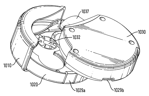
Figure 1 shows a medicament dispenser in accord with the present invention,
comprising a body 10, a holder 20, refill cassette 30 and electronic display
15.
The holder 20 is shaped to fit snugly inside body 10 and is fixed to a point
on the
body (not shown) about which it rotates. Stops 22, 24 protrude from the holder
20 and prevent the holder 20 from rotating more than about 180°
relative to the
CA 02427145 2003-04-28
WO 02/36189 PCT/EPO1/12107
body 10. The stops 22, 24 also provide two defined positions of the holder 20
within the body 10. One position is defined by stop 22 meeting with body edge
12 and the other position defined by stop 24 meeting with body edge 14 when
the holder has been rotated relative to the body. The area between stops 22
and 24 is shaped to form a thumb or finger grip 26 for the user of the device.
The holder 20 forms a shell into which the refill cassette 30 snugly fits.
The refill cassette 30 comprises a shell containing the medicament carrier
(not
shown) and a mechanism for opening the carrier (not shown) for the medicament
to be accessed. The refill cassette 30 has a raised portion 32 at one end on
both sides along its width so that this part of the refill cassette 30 is at
least the
same depth as the part of the holder 28 which receives the refill cassette 30.
This allows the position of the cassette 30 within the holder 20 to be fixed
such
that the ridge 32 protrudes from the holder 20 but the rest of the cassette 30
is
contained within the holder 20.
The refill cassette 30 also has a mouthpiece (not shown) and an indexing lever
35 for indexing the medicament carrier within the cassette 30.
Figure 2 shows the medicament dispenser according to the present invention
with the cassette 130 in place in the holder 120 and body 110 in the non-
dispensing position. The cassetfie 130 is fixed in place by a catch (not
shown).
The catch.can be made to be child resistant to prevent children from removing
the cassette 130 from the holder 110. When the cassette 130 is in the position
shown, relative to the holder 120, the body 110 covers the mouthpiece (not
shown) and a separate mouthpiece cover is therefore not required. The body
110 also protects the indexing lever (not shown) and this prevents accidental
indexing of the medicament carrier (not shown) when the medicament dispenser
is not in use.
Figures 3a and 3b show the medicament dispenser of Figures 1 and 2 with the
cassette 230 in place in the holder 220 in the dispensing position. The holder
220 has been rotated relative to the body 210 so that stop 224 abuts body edge
212. It can be seen that the holder 220 has cut away portions on its depth to
36
CA 02427145 2003-04-28
WO 02/36189 PCT/EPO1/12107
allow access to the indexing lever 235 and the mouthpiece 237. Figure 3b also
shows the attachment point 213 at which the holder 220 is attached to the body
210.
Figure 4 shows a medicament carrier 350 for use herein. The medicament
carrier comprises a peelable blister strip 352 defining a plurality of pockets
354a,
354b each of which contains a dose of medicament which can be inhaled, in the
form of powder.
The strip comprises a base sheet 356 in which blisters are formed to define
the
pockets 354a, 354b and a lid sheet 358 which is hermetically sealed to the
base
sheet except in the region of the blisters in such a manner that the lid sheet
358
and the base sheet 356 can be peeled apart. The sheets 356, 358 are sealed to
one another over their whole width except for the leading end portions 357,
359
where they are preferably not sealed to one another at all. The lid 358 and
base
356 sheets are each preferably formed of a plastics/aluminium laminate and are
preferably adhered to one another by heat sealing.
The strip 352 is shown as having elongate pockets 354a, 354b which run
transversely with respect to the length of the strip 352. This is convenient
in that
it enables a large number of pockets 354a, 354b to be provided in a given
strip
352 length. The strip 352 may, for example, be provided with sixty or one
hundred pockets 354a, 354b but it will be understood that the strip 352 may
have
any suitable number of pockets 354x, 354b.
Figures 5a and 5b show an interns! mechanism of a cassette 430 containing a
medicament carrier 450. Figure 5a shows the medicament carrier 450 in the
situation where the majority of the pockets 454 are still filled with powder.
Figure
5b shows the situation where the majority of pockets 454 are empty and most of
the lid sheet 458 has been removed from the base sheet 456.
The internal mechanism comprises an index wheel 460 and a lid-winding wheel
470 for winding the used portion of the lid sheet 458. The index wheel 460 has
a
plurality of recesses 462x, 462b extending parallel with the axis of the
wheel.
37
CA 02427145 2003-04-28
WO 02/36189 PCT/EPO1/12107
The recesses 462a, 462b are spaced at a pitch which is equal fio the distance
between the centre lines of adjacent pockets 452a, 452b.
The mechanism of the cassette 430 further comprises a lever 435, which
comprises an arcuate wall with a finger tab 437 protruding from the cassette
430
and an arm that extends inwardly from the wall.
The cassette 430 also includes an area 480 for the medicament carrier 450 to
be
coiled in prior to use of the doses contained inside it and an area 482 where
the
used base of the medicament carrier 450 is collected. Area 482 contains base
winding wheel 490 on which the used portion of the base sheet is wound. Also
included is a movable wall 485 to separate these two areas to form two
chambers 480, 482. The movable wall 485 is pushed from the position shown in
figure 5a by the growing coil of collected base sheet to the position shown in
figure 5b, thereby adjusting the size of the chambers.
The lid winding wheel shown in figures 5a and 5b takes the form of a
collapsible
wheel 470. The collapsible wheel 470 has a series of resilient arms 472a, 472b
radiating from a central shaft 474, each at an angle to a radius. The leading
end
of the lid sheet 458 is looped over one of these resilient arms 472a and the
lid
sheet 458 is wound onto the collapsible wheel 470 as it is peeled away from
the
base sheet 456. As more lid sheet 458 is wound onto the collapsible wheel 470,
the resilient arms 470a, 470b gradually flex inwardly, and the effect is to
keep
the external diameter of the reel of wound up lid sheet 458 substantially
constant
while the internal diameter decreases. Guide portion 490 guides the lid sheet
from the point at which it is separated from the base sheet to the lid winding
wheel.
Figure 6 shows an alternative internal mechanism of the cassette which
substitutes for that shown in Figures 5a and 5b. The mechanism is shown
without the medicament carrier in place, without the base winding wheel,
chambers for housing the medicament carrier or the movable wall to separate
the chambers. The lever is also not shown.
38
CA 02427145 2003-04-28
WO 02/36189 PCT/EPO1/12107
The mechanism comprises index wheel 560 and lid winding roller 570. The
index wheel 560 has a plurality of recesses 562a, 562b spaced at a pitch equal
to the distance between the centre lines of adjacent pockets 552a, 552b in the
medicament carrier. The mechanism also comprises guide portions 590 and
595 which guide the lid and base sheets (not shown) away from each other and
toward the base winding wheel (not shown) or lid winding roller 570 as
appropriate. The used portion of the lid sheet is gripped tightly by the
roller 570
as it passes through from the guide portion 590 and is then passed out into
the
rest of the cassette to collect in a chamber. Use of the roller 570 has the
advantage over the collapsing wheel in that the leading end of the lid sheet
does
not need to be tied on but is merely gripped by the roller 570, therefore
simplifying the assembly process.
In operation, the user moves the holder relative to the body to move the
cassette
into the dispensing position and then presses on the finger tab of the lever
to
cause it to move. This leads to rotation of the index wheel which results in
rotation of both the base winding wheel and the lid winding wheel, thus
peeling
the base sheet and lid sheet apart over a distance sufficient to expose a
previously unopened pocket opposite the end of the powder outlet. The patient
can then inhale the powdered medicament through the mouthpiece.
A further alternative internal mechanism is shown in Figures 7a and 7b. The
mechanism comprises an index wheel 660 and a lid spool 670. The lid spool 670
comprises a toothed wheel 672 with a central upward cylindrical projection on
which the lid sheet 658 is wound when it has been separated from the base
sheet. The index wheel 660 is similar to that shown in Figures 5 and 6 and has
a plurality of recesses 662a, 662b spaced at a pitch equal to the distance
between the centre lines of adjacent pockets 664 in the medicament carrier
650.
The index wheel 660 however, additionally has a plurality of indentations
664a,
664b which are spaced at intervals in between the recesses 662a, 662b. The
teeth 672 on the base of the lid spool fit into the teeth 646 on the indexing
lever
640 on its mid portion. The lid spool 670 is driven by movement of the index
lever 640 and its interaction with the teeth 646 on this lever 640.
39
CA 02427145 2003-04-28
WO 02/36189 PCT/EPO1/12107
As more lid sheet 658 is wound around the lid spool 670 its diameter increases
therefore a mechanism is required to ensure that the medicament carrier 650 is
indexed by the same amount each time. Interlock coupling 665 comprises a foot
portion 666 having a toe 667 and a heel 668, and a tail section 669. The
interlock coupling 665 is pivotally mountable to the cassette at its foot
portion
666. The toe 667 of the interlock coupling 665 is shaped to fit in an
indentation
664 on the index wheel 660 and the heel 668 is able to communicate with the
teeth on the tail section 644 of the indexing lever 640. The interlock
coupling
665 is sprung biased towards the index wheel 660. A ratchet pawl is provided
on the lid spool 670 to stop the used portion of the lid sheet 658 from
unwinding
from the lid spool 670 and to ensure that the tension in the wound lid sheet
658
is maintained.
Figure 7a shows the mechanism when the index lever 640 has been marginally
moved from its rest position. It can be seen that the toe 667 of the interlock
coupling 665 has just been moved out of an indent 664 in the index wheel 660.
The heel 668 of the interlock coupling 665 is in contact with the indexing
lever
640. The tail section 669 of the interlock coupling 665 is in contact with a
projection 646 from the index lever 640. The unused portion of the blister
strip
652 is fed onto the index wheel 660 and the lid sheet 658 is then separated
from
the base sheet 656 and passes around a roller guide 688 before being wound
around the lid spool 670.
As the indexing lever 640 is moved by the patient, the lid spool 670 is turned
by
interaction with the teeth on the lever 640, resulting in the lid sheet 658
being
peeled away from the base sheet 656 and wound around the lid spool 670. The
index wheel 660 is turned as the lid sheet 658 is peeled away until the toe
667 of
the interlock coupling inserts into the next indentation 664. The heel 668 of
the
interlock coupling 665 moves against the tail end of the indexing lever 640
and
interacts with the teeth 644 on this part of the indexing lever 640. The tail
section 669 of the interlock coupling 665 is swung around the projection 648
on
the lever 640 so that the projection 648 gradually travels along the tail
section
669 of the interlock coupling 665 towards its middle.
CA 02427145 2003-04-28
WO 02/36189 PCT/EPO1/12107
The positioning of the mechanism when the index lever 640 has been fully
moved is shown in Figure 7b. The toe 667 of the interlock coupling 665 has
been inserted into the next indentation 664 and the heel 668 has fitted into
the
teeth 644 at the tail end of the indexing lever 640 to lock the lever 640 in
place
so that it can not be moved any further. The next pocket 654 on the blister
strip
650 is aligned with the mouthpiece (not shown) and air inlet (not shown) ready
for inhalation by the patient.
Figure 8 shows a refill cassette with an alternative indexing mechanism
herein.
The mechanism comprises a number of recesses 748x, 748b located on an arm
of the indexing lever 740 which protrudes into the cassette 730. The recesses
748a, 748b are shaped and sized to engage the pockets in a blister strip (not
shown). When the indexing lever 740 is moved by the patient the blister strip
is
indexed by one pocket. Resetting the lever 740 back to its rest position
results
in the fever 740 disengaging the strip temporarily and then reengaging it one
pocket further along. This mechanism has the advantage in that it is simple
and
reduces the number of components required within the device, therefore
reducing both the overall cost of the device components and the cost of
assembling it.
Figures 9a to 9c illustrate a medicament dispenser according to another aspect
of the present invention. The medicament dispenser comprises a body cover
810, a holder 820, refill cassette 830 and electronic display 815. The holder
820
is shaped to fit snugly inside body 810 to a point on the body 813 about which
it
rotates. Stops 822, 824 protrude from the holder 820 to prevent the holder 820
from rotating more than about 110° relative to the body cover 810. The
stops
822, 824 also provide two defined positions of the holder 820 within the body
cover 810. One position is defined by stop 822 meeting with body edge 812 and
the other position defined by stop 824 meeting with body edge 814 when the
holder has been rotated relative to the body. The holder 820 forms a shell
into
which the refill cassette 830 snugly fits.
The refill cassette 830 comprises a shell body containing the medicament
carrier
(not shown) and an internal mechanism for opening the carrier (not shown) for
41
CA 02427145 2003-04-28
WO 02/36189 PCT/EPO1/12107
the medicament to be accessed. The refill cassette 830 has a mouthpiece 837
arranged such that in use, the mouthpiece 837 protrudes from fihe holder 820
but
the bulk of the cassette 830 is contained within the holder 820.
Figure 10 illustrates a further medicament dispenser according to another
aspect
of the present invention. The medicament dispenser comprises a body cover
910, a holder 920 and refill cassette 930. The holder 920 is shaped to fit
snugly
inside body 910 to a point on the body (not shown) about which it rotates.
Stops
922, 924 protrude from the holder 920 to prevent the holder 920 from rotating
more than about 180° relative to the body cover 910. The stops 922, 924
also
provide two defined positions of the holder 920 within the body cover 910. One
position is defined by stop 922 meeting with body edge 912 and the other
position defined by stop 924 meeting with body edge 914 when the holder has
been rotated relative to the body. The holder 920 forms a shell into which the
refill cassette 930 snugly fits by way of a side loading engagement.
The refill cassette 930 comprises a shell body containing the medicament
carrier
(not shown) and an internal mechanism 932 for opening the carrier for the
medicament to be accessed. The refill cassette 930 has a mouthpiece 937
arranged such that in use, the mouthpiece 937 protrudes from the holder 920
but
the bulk of the cassette 930 is contained within the holder 920.
Figure 11 illustrates a further medicament dispenser according to another
aspect
of the present invention. The medicament dispenser comprises a body cover
1010, a holder 1020 and refill cassette 1030. The holder 1020 is shaped to fit
snugly inside body 1010 to a point on the body (not shown) about which it
rotates. The holder 1020 forms a landing station with which the refill
cassette
1030 snugly engages by way of a face-to-face snap-fit 1029a, 1029b
engagement. When so engaged, the holder 1020 . and the cassette 1030 in
combination form the bulk of the overall 'body form' of the medicament
dispenser.
The refill cassette 1030 comprises a shell body containing the medicament
carrier (not shown) and an internal mechanism 1032 for opening the carrier for
42
CA 02427145 2003-04-28
WO 02/36189 PCT/EPO1/12107
the medicament to be accessed. The refill cassette 1030 has a mouthpiece
1037 arranged such that in use, the mouthpiece 1037 protrudes from the
dispenser.
It may be appreciated that any of the parts of the dispenser or actuator which
contact the medicament suspension may be coated with materials such as
fluoropolymer materials (e.g. PTFE or FEP) which reduce the tendency of
medicament to adhere thereto. Any movable parts may also have coatings
applied thereto which enhance their desired movement characteristics.
Frictional
coatings may therefore be applied to enhance frictional contact and lubricants
(e.g. silicone oil) used to reduce frictional contact as necessary.
The medicament dispenser of the invention is suitable for dispensing
medicament, particularly for the treatment of respiratory disorders such as
asthma and chronic obstructive pulmonary disease (COPD).
Appropriate medicaments may thus be selected from, for example, analgesics,
e.g., codeine, dihydromorphine, ergotamine, fentanyl or morphine; anginal
preparations, e.g., diltiazem; antiallergics, e.g., cromoglycate (eg s the
sodium
salt), ketotifen or nedocromil (eg as the sodium salt); antiinfectives e.g.,
cephalosporins, penicillins, streptomycin, sulphonamides, tetracyclines and
pentamidine; antihistamines, e.g., methapyrilene; anti- inflammatories, e.g.,
beclomethasone (eg as the dipropionate ester), fluticasone (eg as the
propionate
ester), flunisolide, budesonide, rofleponide, mometasone eg as the furoate
ester), ciclesonide, triamcinolone (eg as the acetonide) or 6a, 9a-difluoro-11
[i-
hydroxy-16a-methyl-3-oxo-17a-propionyloxy-androsta-1,4-diene-17[i-carbothioic
acid S-(2-oxo-tetrahydro-furan-3-yl) ester; antitussives, e.g., noscapine;
bronchodilators, e.g., albuterol (eg as free base or sulphate), salmeterol (eg
as
xinafoate), ephedrine, adrenaline, fenoterol (eg as hydrobromide), formoterol
(eg
as fumarate), isoprenaline, metaproterenol, phenylephrine,
phenylpropanolamine, pirbuterol (eg as acetate), reproterol (eg as
hydrochloride), rimiterol, terbutaline (eg as sulphate), isoetharine,
tulobuterol or
4-hydroxy-7-[2-[[2-[[3-(2-phenylethoxy)propyl]sulfonyl]ethylJamino]ethyl-2(3H)-
43
CA 02427145 2003-04-28
WO 02/36189 PCT/EPO1/12107
benzothiazolone; adenosine 2a agonists, eg 2R,3R,4S,5R)-2-[6-Amino-2-(1 S-
hydroxymethyl-2-phenyl-ethylamino)-purin-9-yl]-5-(2-ethyl-2H-tetrazol-5-yl)-
tetrahydro-furan-3,4-diol (e.g. as maleate); a4 integrin inhibitors eg (2S)-3-
[4-({[4-
(aminocarbonyl)-1-piperidinyl]carbonyl)oxy)phenyl]-2-[((2S)-4-methyl-2-{[2-(2-
methylphenoxy) acetyl]amino}pentanoyl)amino] propanoic acid (e.g as free acid
or potassium salt), diuretics, e.g., amiloride; anticholinergics, e.g.,
ipratropium
(eg as bromide), tiotropium, atropine or oxitropium; hormones, e.g.,
cortisone,
hydrocortisone or prednisolone; xanthines, e.g., aminophylline, choline
theophyllinate, lysine theophyllinate or theophylline; therapeutic proteins
and
peptides, e.g., insulin or glucagon; vaccines, diagnostics, and gene
therapies. It
will be clear to a person skilled in the art that, where appropriate, the
medicaments may be used in the form of salts, (e.g., as alkali metal or amine
salts or as acid addition salts) or as esters (e.g., lower alkyl esters) or as
solvates (e.g., hydrates) to optimise the activity and/or stability of the
medicament.
Preferred medicaments are selected from albuterol, salmeterol, fluticasone
propionate and beclomethasone dipropionate and salts or solvates thereof,
e.g.,
the sulphate of albuterol and the xinafoate of salmeterol.
Medicaments can also be delivered in combinations. Preferred formulations
containing combinations of active ingredients contain salbutamol (e.g., as the
free base or the sulphate salt) or salmeterol (e.g., as the xinafoate salt) or
formoterol (eg as the fumarate salt) in combination with an antiinflammatory
steroid such as a beclomethasone ester (e.g., the dipropionate) or a
fluticasone
ester (e.g., the propionate) or budesonide. A particularly preferred
combination
is a combination of fluticasone propionate and salmeterol, or a salt thereof
(particularly the xinafoate salt). A further combination of particular
interest is
budesonide and formoterol (e.g. as the fumarate salt).
Generally, powdered medicament particles suitable for delivery to the
bronchial
or alveolar region of the lung have an aerodynamic diameter of less than 10
micrometers, preferably less than 6 micrometers. Other sized particles may be
44
CA 02427145 2003-04-28
WO 02/36189 PCT/EPO1/12107
used if delivery to other portions of the respiratory tract is desired, such
as the
nasal cavity, mouth or throat. The medicament may be delivered as pure drug,
but more appropriately, it is preferred that medicaments are delivered
together
with excipients (carriers) which are suitable for inhalation. Suitable
excipients
include organic excipients such as polysaccharides (i.e. starch, cellulose and
the
like), lactose, glucose, mannitol, amino acids, and maltodextrins, and
inorganic
excipients such as calcium carbonate or sodium chloride. Lactose is a
preferred
excipient.
Particles of the powdered medicament and/or excipient may be produced by
conventional techniques, for example by micronisation, milling or sieving.
Additionally, medicament and/or excipient powders may be engineered with
particular densities, size ranges, or characteristics. Particles may comprise
active agents, surfactants, wall forming materials, or other components
considered desirable by those of ordinary skill.
The excipient may be included with the medicament via well known methods,
such as by admixing, co-precipitating and the like. Blends of excipients and
drugs are typically formulated to allow the precise metering and dispersion of
the
blend into doses. A standard blend, for example, contains 13000 micrograms
lactose mixed with 50 micrograms drug, yielding an excipient to drug ratio of
260:1. Dosage blends with excipient to drug ratios of from 100:1 to 1:1 may be
used. At very low ratios of excipient to drug, however, the drug dose
reproducibility may become more variable.
It will be understood that the present disclosure is for the purpose of
illustration
only and the invention extends to modifications, variations and improvements
thereto.
The application of which this description and claims form part may be used as
a
basis for priority in respect of any subsequent application. The claims of
such
subsequent application may be directed to any feature or combination of
features described therein. They may take the form of product, method or use
CA 02427145 2003-04-28
WO 02/36189 PCT/EPO1/12107
claims and may include, by way of example and without limitation, one or more
of the following claims:
46