Note: Descriptions are shown in the official language in which they were submitted.
CA 02427793 2003-05-05
DOCKET NO. 17851 (MHM 13612US01)
ELECTRICAL CONNECTOR WITH DUAL RACK MATE ASSIST
BACKGROUND OF THE INVENTION
[01] Certain embodiments of the present invention generally relate to a lever-
based
connection assembly for engaging resisting components. More particularly,
certain
embodiments of the present invention relate to a mate assist assembly for
connecting
electrical contacts contained in separate housings.
[02] In certain applications, electronic components require a mate assist
assembly to
electrically connect several electrical contacts. The mate assist assembly
includes a first
connector housing that holds several electrical contacts, and a second
connector housing that
holds an equal number of electrical contacts. One connector housing includes
male electrical
contacts, while the other connector housing includes female electrical
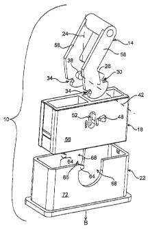
contacts. The first
connector housing is configured to be received inside the second connector
housing. As the
number of electrical contacts to be mated increases, it becomes difficult to
fully join the
mating connector housings because of friction between the mating electrical
contacts.
[03] A conventional mate assist assembly includes a lever having a handle and
two lever
arms that extend from, and are rotated alongside, side walls of the first
connector housing.
The second connector housing is slid onto and encloses the first connector
housing to a point
where the electrical contacts resist further insertion. Each lever arm
includes a cam arm with
notches. Rack teeth are situated within the second connector housing with each
rack tooth
corresponding to the notches of the cam arms. As the first connector housing
is inserted into
the second connector housing, the lever is oriented in a fixed position so
that the cam arms
are aligned to engage the rack teeth.
[04] As the handle is rotated in a first direction, the rack teeth and cam
arms engage and
pull the first connector housing and lever downward into the second connector
housing,
mating the electrical contacts. Alternatively, as the handle is rotated in a
second direction,
the first connector housing is pulled upward out of the second connector
housing, unmating
the electrical contacts.
1
CA 02427793 2003-05-05
[051 The conventional electrical connector suffers from a number of drawbacks.
First, the
lever member is rotated a large distance before the cam arms engage the rack
teeth on the
module connector. Therefore, the lever member rotates ninety-degrees to fully
connect and
disconnect the electrical contacts. Since the lever member rotates ninety-
degrees in
operation, the lever member is fully upright and parallel to a vertical axis
at some point
during the course of rotation. When the lever member is in such an upright
orientation, the
mate assist assembly takes up a large amount of space and is thus limited to
use in certain
electronic applications where space is not constrained. Therefore, a mate
assist assembly is
needed having a lever member that rotates a shorter distance to connect the
electrical contacts
and thus takes up less space during rotation.
[061 Secondly, conventional electrical connectors do not effectively maintain
the lever
members in the necessary fixed position. For example, some electrical
connectors have
apertures in the lever arms that receive, and are retained by, deflectable
latches extending
outward from the side walls of the first connector housing. When the first
connector housing
is positioned within the second connector housing, the latches are biased
inward into the first
connector housing to release the lever arms from the fixed position. However,
the lever arms
must be in a lowered position about the first connector housing for the
deflectable latches to
engage the apertures. In order to position the first connector housing
downward into the
second connector housing, the lever is rotated upward to an upright position
above the first
connector housing. The lever therefore takes up more space and interferes with
surrounding
components when connecting the electrical contacts, thus limiting the number
of components
with which the electrical connector is used.
[071 Other electrical connectors maintain the lever in a fixed position with
the lever arms
extending upright from the first connector housing prior to insertion into the
second
connector housing so that the lever is rotated downward about the first
connector housing to
connect the electrical contacts. The lever arms include apertures near the cam
arms that
receive, and are retained by, protrusions extending out from the side walls of
the first
connector housing. When the first connector housing is positioned within the
second
connector housing, the lever is pushed with a force necessary to disengage the
apertures from
the protrusions to release the lever from the fixed position. However, the
protrusions are
small and engage only a small amount of surface area of the lever arms.
Therefore, when
slight forces are applied to the lever, the lever arms are prematurely
released from the
2
CA 02427793 2010-05-31
67789-499
protrusions such that the lever is no longer in the fixed position. The
protrusions
also quickly wear down until the protrusions do not engage the lever.
[08] Therefore, a need exists for an electrical connector that overcomes
the above problems and addresses other concerns experienced in the prior art.
BRIEF SUMMARY OF THE INVENTION
[09] Certain embodiments of the present invention provide for an
electrical connector including first and second housings having ends
configured to
receive electrical contacts. The first and second housings are configured to
be
matable with one another to join corresponding electrical contacts and are
movable between initial and final positions. The electrical connector also
includes
a lever member engaging the first and second housings and moving the first and
second housings between the initial and final positions as the lever member is
rotated through a range of motion about a rotational axis. The lever member
includes a cam arm having a pivot post received by the first housing and first
and
second notches that engage the first and second housings, respectively. The
first
housing includes a post slot for rotatably and slidably retaining the pivot
post
relative to the rotational axis. The first housing further has a first rack
engaging
the first notch, and the second housing has a second rack engaging the second
notch. The first and second racks and notches cooperate to move the first and
second housings between the initial and final positions as the lever member is
rotated along the range of motion.
According to one aspect of the present invention, there is provided
an electrical connector, comprising: first and second housings being
configured to
receive electrical contacts, said first and second housings being configured
to be
matable with one another to join corresponding electrical contacts, said first
and
second housings being movable between initial and final positions; a lever
member engaging said first and second housings and moving said first and
second housings between said initial and final positions as said lever member
is
rotated through a range of motion about a rotational axis, said lever member
including a cam arm having a pivot post received by said first housing, said
lever
3
CA 02427793 2010-05-31
67789-499
member including first and second cam surfaces that engage said first and
second
housings, respectively; and said first housing having a post slot for
rotatably and
slidably retaining said pivot post relative to said rotational axis, said
first housing
further having a first engagement means engaging said first cam surface, said
second housing having a second engagement means engaging said second cam
surface, said first and second engagement means and cam surfaces cooperating
to move said first and second housings between said initial and final
positions as
said lever member is rotated along said range of motion, wherein said first
and
second engagement means respectively comprise first and second racks, said
first and second cam surfaces respectively comprise first and second notches
and
said cam arm is positioned within a U-shaped or semi-circular arm catch in a
side
wall of said second housing in said initial position.
According to another aspect of the present invention, there is
provided an electrical connector comprising: first and second housings having
ends configured to receive electrical contacts, said first and second housings
being configured to be matable with one another to join corresponding
electrical
contacts, said first and second housings being movable between initial and
final
positions; a lever member having a cam arm that engages said first and second
housings and moves said first and second housings between said initial and
final
positions as said lever member is rotated through a range of motion about a
rotational axis and along a linear path; and a multidimensional linkage
interconnecting said lever member and said first housing and permitting said
lever
member to rotate about said rotational axis and along said linear path
relative to
said first housing when moving said first and second housings between said
initial
and final positions as said lever member is rotated through said range of
motion;
wherein said cam arm is positioned within a U-shaped or semi-circular arm
catch
in a side wall of said second housing in said initial position.
According to still another aspect of the present invention, there is
provided an electrical connector comprising: first and second housings having
ends configured to receive electrical contacts, said first and second housings
being configured to be matable with one another to join corresponding
electrical
3a
CA 02427793 2010-05-31
67789-499
contacts, said first and second housings being movable between initial and
final
positions, said first and second housings having first and second racks,
respectively; and a lever member rotatably connected to said first housing
having
a cam arm that engages said first and second racks and moves said first and
second housings between said initial and final positions as said lever member
is
rotated through a range of motion about a rotational axis, said first and
second
racks being spaced radially apart from said rotational axis; wherein said cam
arm
is positioned within a U-shaped or semi-circular arm catch in a side wall of
said
second housing in said initial position.
BRIEF DESCRIPTION OF SEVERAL VIEWS OF THE DRAWINGS
[10] Figure 1 illustrates a side isometric view of a mate assist assembly
according to an embodiment of the present invention.
[11] Figure 2 illustrates an exploded isometric view of the mate assist
assembly of Fig. 1.
[12] Figure 3 illustrates an isometric view of a harness connector formed
according to an embodiment of the present invention.
[13] Figure 4 illustrates an isometric view of a lever member formed
according to an embodiment of the present invention.
3b
CA 02427793 2003-05-05
[14] Figure 5 illustrates an isometric view of the lever member mounted to the
harness
connector.
[15] Figure 6 illustrates an isometric view of a module connector formed
according to an
embodiment of the present invention.
[16] Figure 7 illustrates a side isometric view of the mate assist assembly in
the final
position and the electrical contacts fully mated.
[17] Figure 8 illustrates a mate assist assembly formed in accordance with an
alternative
embodiment of the present invention.
[18] Figure 9 illustrates a side isometric view of a mate assist assembly of
Fig. 8 in the
final position.
[19] Figure 10 illustrates a side view of a mate assist assembly formed in
accordance with
an alternative embodiment of the present invention.
[20] The foregoing summary, as well as the following detailed description of
certain
embodiments of the present invention, will be better understood when read in
conjunction
with the appended drawings. For the purpose of illustrating the invention,
there is shown in
the drawings, certain embodiments. It should be understood, however, that the
present
invention is not limited to the arrangements and instrumentality shown in the
attached
drawings.
DETAILED DESCRIPTION OF THE INVENTION
[21] Figure 1 illustrates a side isometric view of a mate assist assembly 10
formed
according to an embodiment of the present invention. The mate assist assembly
10 includes a
harness connector 18 having contact pockets 12 configured to receive packets
that hold
groups of electrical contacts (not shown). The mate assist assembly 10 also
includes a
module connector 22 that holds electrical contacts (not shown) configured to
mate with the
electrical contacts in the harness connector 18. As shown in Fig. 1, the
harness connector 18
is partially inserted within the module connector 22 to an initial staging
position. The mate
assist assembly 10 also includes a lever member 14 that is retained on the
exterior of the
harness connector 18 and engages the module connector 22. The lever member 14
is
rotatable in the direction of arrow A to move the harness connector 18 from
the initial staging
4
CA 02427793 2003-05-05
position to a final position (Fig. 8). As the lever member 14 is rotated in
the direction of
arrow A, it pushes the harness connector 18 downward in the direction of arrow
B into the
module connector 22 until fully mating the electrical contacts of the harness
connector 18 and
the module connector 22 with each other.
[22] Figure 2 illustrates an exploded isometric view of the mate assist
assembly 10 of Fig.
1. The lever member 14 includes a pair of spaced apart cam arms 26, each of
which has first
and second notches 30 and 34 located on opposite sides thereof. The cam arms
26 also
include cylindrical pivot posts 38 extending inward from interior surfaces
thereof and facing
one another. The pivot posts 38 are aligned along a common rotational axis 42.
In Fig. 2, the
lever member 14 is oriented in an unmated position with lever arms 58 aligned
by way of
example only, at a thirty-degree angle to a vertical axis 24. The vertical
axis 24 extends
parallel to the direction of relative motion between the harness connector 18
and module
connector 22. The harness connector 18 includes triangular first racks 48
situated beside oval
post slots 52 formed through the side walls 56. The module connector 22
includes
rectangular side walls 72 having a U-shaped or semi-circular arm catches 68
cut out.
Triangular second racks 64 are formed on one side of the arm catches 68
proximate an open
face 65 of the module connector 22.
[23] The lever member 14 is removably inserted downward in the direction of
arrow B
(also referred to as the loading or staging direction) into the harness
connector 18 into a fixed
position at which the pivot posts 38 are received within the post slots 52 and
the first racks 48
are located within the first notches 30 such that the lever arms 58 are
aligned generally at a
thirty-degree angle to the vertical axis 24. The harness connector 18 and
lever member 14
are then slidably inserted in the direction of arrow B into the module
connector 22 until
reaching the initial staging position shown in Fig. 1. When in the initial
staging position, the
cam arms 26 are positioned within the arm catches 68 and the second racks 64
are positioned
within the second notches 34.
[24] Figure 3 illustrates an isometric view of the harness connector 18 formed
according to
an embodiment of the present invention. The harness connector 18 is box shaped
and
includes opposing side walls 56 and opposing end walls 76. By way of example
only, a
center wall 74 may extend between the side walls 56 to define multiple square
contact
pockets 12. Electrical contacts (not shown) may be loaded into the contact
pockets 12 from
CA 02427793 2003-05-05
either a face 75 or a rear end 73 of the harness connector 18. When the
harness connector 18
is slidably inserted into the module connector 22 (Fig. 2), the electrical
contacts engage the
electrical contacts situated in the module connector 22. An exterior perimeter
of the harness
connector 18 is smaller than an interior perimeter of the module connector 22,
in order that
the harness connector 18 may be positioned within the module connector 22.
[251 The post slots 52 are elliptical in shape with interior walls 84, top
wall 90, and bottom
wall 88, along longitudinal axis extending between the face 75 and rear end
73. The post
slots 52 include interior walls 84 having oppositely aligned retention bumps
80 extending
inward toward one another. The pivot posts 38 of the cam arms 26 (Fig. 2) are
initially
retained within a lower position of the post slots 52 between the retention
bumps 80 and
bottom walls 88 of the post slots 52. The retention bumps 80 permit the pivot
posts 38 to
rotate freely, while being held in the lower position, until the harness
connector 18 is inserted
to the initial staging position within the module connector 22 (Fig. 2). As
the lever member
(Fig. 1) is rotated in the direction of arrow A, the pivot posts 38 are pried
upward in the
direction of arrow C until squeezing between the retention bumps 80 and moving
to an upper
position in the post slots 52 between the retention bumps 80 and top wall 90.
The pivot posts
38 are free to rotate within the upper position.
[26] The post slots 52 are located between opposed oval flex holes 92. The
flex holes 92
extend through the side walls 56 and are oriented with their longitudinal axis
aligned parallel
to the longitudinal axis of the post slots 52. Narrow flex strips 96 separate
the post slots 52
and flex holes 92. As the pivot posts 38 of the cam arms 26 (Fig. 2) are
pushed upward in the
direction of arrow C from the lower position to the upper position, the pivot
posts 38 deflect
the retention bumps 80 outward away from each other. The flex strips 96 bow
outward in
opposite directions into the flex gaps 92, as the retention bumps 80 are
deflected away from
each other. Once the pivot posts 38 are moved into an upper position 89 above
the retention
bumps 80, the flex strips 96 spring back toward each other out of the flex
gaps 92 such that
the retention bumps 80 are returned to an unbiased state underneath the pivot
posts 38.
[271 The first racks 48 extend outward opposite each other from the side walls
56 and are
located along one side of the post slots 52. The first racks 48 are generally
aligned proximate
a midpoint of the interior walls 84. Each of the first racks 48 has sloped top
and bottom
surfaces 100 and 104 that are received within the first notches 30 of the cam
arms 26 (Fig. 2)
6
CA 02427793 2003-05-05
when the lever member 14 (Fig. 2) is mounted on the harness connector 18. The
top and
bottom surfaces 100 and 104 engage the first notches 30 when the pivot posts
38 are in the
lower position 87 in the post slots 52 to hold the lever arms 58 into the
fixed position while
the harness connector 18 is loaded into the module connector 22 to the initial
staging
position. As the harness connector 18 is moved from the initial staging
position to the final
position in the module connector 22, the first racks 48 slide into the arm
catches 68 of the
module connector 22 (Fig. 2).
[281 The end walls 76 on the harness connector 18 include exterior recessed
portions 108
aligned vertically and having retention strips 112 traversing the recessed
portions 108
laterally. As the harness connector 18 is slid into the module connector 22
(Fig. 2), the
retention strips 112 snapably engage top and bottom retention latches 116 and
118 (Fig. 6)
positioned on interior surfaces of end walls 132 of the module connector 22
thereby retaining
the harness connector 18.
1291 Figure 4 illustrates an isometric view of the lever member 14 formed
according to an
embodiment of the present invention. A handle 120 is formed integral with, and
extends
perpendicularly between, the lever arms 58, which are in turn formed with the
cam arms 26.
The first and second notches 30 and 34 within the cam arms 26 have oppositely
aligned top
and bottom gear surfaces 124 and 128, and 125 and 129, respectively. The first
notches 30
engage the first racks 48 of the harness connector 18 (Fig. 3) to retain the
lever member 14 in
the fixed position prior to insertion into the module connector 22. The first
and second
notches 30 and 34 engage the first racks 48 on the harness connector 18 and
the second racks
64 (Fig. 2) on the module connector 22, respectively, as the lever member 14
is rotated
between its initial and final positions.
[301 Figure 5 illustrates an isometric view of the lever member 14 mounted to
the harness
connector 18. The lever member 14 is attached to the harness connector 18 by
deflecting the
lever arms 58 outward away from each other so that the pivot posts 38 (Fig. 2)
slide along the
side walls 56 of the harness connector 18 until the pivot posts 38 are
enclosed within the post
slots 52 between the retention bumps 80 (Fig. 3) and the bottom walls 84 (Fig.
3) and the first
notches 30 enclose the first racks 48 of the harness connector 18. The top and
bottom gear
surfaces 124 and 128 of the first notches 30 resistibly engage the top and
bottom surfaces 100
7
CA 02427793 2003-05-05
and 104, respectively, of the first racks 48 such that the lever member 14 is
maintained in the
fixed position with the lever arms 58 generally at a thirty-degree angle to
the vertical axis 24.
[31] The post slots 52 help maintain the lever member 14 in the fixed position
prior to
inserting the harness connector 18 into the module connector 22 (Fig. 2). The
retention
bumps 80 (Fig. 3) hold the pivot posts 38 (Fig. 2) in the lower position 87
(Fig. 3) within the
post slots 52 (Fig. 3), preventing the pivot posts 38 from sliding into the
upper position 89
(Fig. 3) within the post slots 52 such that the first notches 30 become
disengaged from the
first racks 48 and the lever member 14 rotates out of the fixed position. When
the lever
member 14 is in the fixed position and the harness connector 18 is in the
initial staging
position within the module connector 22, the cam arms 26 are aligned such that
the second
notches 34 receive the second racks 64 (Fig. 2) of the module connector 22.
The second
racks 64 and the second notches 34 are then aligned to engage each other when
the lever
member 14 is rotated to move the harness connector 18 from the initial staging
position to the
final position.
[32] Figure 6 illustrates an isometric view of the module connector 22 formed
according to
an embodiment of the present invention. The side walls 72 are formed integral
with, and are
aligned perpendicular to, end walls 132. The side and end walls 72 and 132 are
formed
integral with, and extend from, a base 134, which has a larger perimeter than
a perimeter
about the side and end walls 72 and 132. The base 134 is mounted to an
electronic
component (not shown), such as a radio, with the side and end walls 72 and 132
extending
outward from the electronic component. The electrical contacts positioned
within the module
connector 22 are connected to the electronic component through contact slots
(not shown).
When the harness connector 18 (Fig. 3) is in the final position within the
module connector
22, the electrical contacts of the harness and module connectors 18 and 22 are
fully mated.
[33] The side walls 72 include the arm catches 68 positioned in the center
thereof. The
second racks 64 extend into the arm catches 68 at first sides along a top edge
138 of the side
walls 72. The second racks 64 have sloped top and bottom surfaces 142 and 146
that engage
the second notches 34 on the cam arms 26 (Fig. 4). When the cam arms 26 are
rotated to
position the harness connector 18 into the final position, the second racks 64
resistibly engage
the second notches 34 as described below to pull the harness connector 18
downward into the
module connector 22 such that the cam arms 26 and the first racks 48 are
positioned within
8
CA 02427793 2003-05-05
the arm catches 68. The first racks 48 and the second racks 64 are positioned
on the harness
connector 18 and module connector 22, respectively, such that when the harness
connector 18
is in the final position, the first racks 48 and the second racks 64 are
located within the arm
catches 68 along opposite side walls 150. Thus, the alignment of the first
racks 48 and the
second racks 64 within the harness connector 18 and the module connector 22,
respectively,
enable the harness connector 18 to be inserted into the module connector 22 in
a correct
orientation.
[34] The end walls 132 include the top and bottom retention latches 116 and
118 that
snapably engage and retain the retention strips 112 of the harness connector
18 (Fig. 3). As
the harness connector 18 is lowered into the module connector 22 into the
initial staging
position, the retention strips 112 snapably slide over the top retention
latches 116 into gaps
122 between the top and bottom retention latches 116 and 118. The top and
bottom retention
latches 116 and 118 thus retain the retention strips 112 and the harness
connector 18 in the
initial staging position. As the harness connector 18 is moved from the
initial staging
position to the final position, the retention strips 112 snapably slide past
and under the bottom
retention latches 118. When the harness connector 18 is removed from the
module connector
22, the retention strips 112 snapably slide back over the bottom and top
retention latches 118
and 116.
[35] Returning to Fig. 1, the harness connector 18 is in the initial staging
position with the
lever member 14 upright in the fixed position. The first racks 48 engage the
first notches 30
at a first contact point 156 that is separated from the rotational axis 42 by
a pitch radius DI
and the second racks 64 engage the second notches 34 at a second contact point
160 that is
separated from the rotational axis 42 by a pitch radius D2. By way of example
only, D1 is
equal to D2.
[36] To move the harness connector 18 into the final position and mate the
electrical
contacts, the lever member 14 is rotated about the rotational axis 42 in the
direction of arrow
A, for example, by approximately sixty degrees until the lever arms 58 rest on
the top edges
138 of the module connector 22 perpendicular to the vertical axis 24. As the
lever member
14 is rotated in the direction of arrow A, the top gear surfaces 124 of the
first notches 30 push
against the top surfaces 100 of the first racks 48 in the direction of arrow J
and the bottom
gear surfaces 129 of the second notches 34 push against the bottom surfaces
146 of the
9
CA 02427793 2003-05-05
second racks 64 in the direction of arrow K. As the top gear surfaces 124 and
the top
surfaces 100 engage one another, the bottom gear surfaces 129 of the second
notches 34 push
against the bottom surfaces 146 of the second racks 64 in the direction of
arrow K. The dual
contact between the first notches 30 and the first racks 48 and the second
notches 34 and the
second racks 64 pull the cam arms 26 into the arm catches 68 and thus pull the
harness
connector 18 into the module connector 22 with enough force to mate the
electrical contacts.
[371 Figure 7 illustrates a side isometric view of the mate assist assembly 10
in the final
position with the electrical contacts mated. The cam arms 26 and the first
racks 48 are
positioned within the arm catches 68 with the top gear surfaces 124 of the
first notches 30
against the top surfaces 100 of the first racks 48 and the bottom gear
surfaces 129 of the
second notches 34 against the bottom surfaces 146 of the second racks 64. The
lever arms 58
are aligned perpendicular to the vertical axis 24, but could be oriented to
another angle. To
disengage the electrical contacts and return the harness connector 18 to the
initial staging
position, the lever member 14 is rotated in the direction of arrow S about the
rotational axis
42. As the lever member 14 is rotated in the direction of arrow S, the bottom
gear surfaces
128 of the first notches 30 push against the bottom surfaces 104 of the first
racks 48 in the
direction of arrow T and the top gear surfaces 125 of the second notches 34
push against the
top surfaces 142 of the second racks 64 in the direction of arrow Q. The force
exerted
between the first and second notches 30 and 34 and the first and second racks
48 and 64,
respectively, is sufficient to overcome the static friction of the mated
electrical contacts and
lift the harness connector 18 upward in the direction of arrow C out of the
module connector
22 the initial staging position.
[38] Returning to Fig. 1, when the harness connector 18 is in the initial
staging position,
the pivot posts 38 (Fig. 2) are in the lower position 87 (Fig. 3) within the
post slots 52 (Fig.
3). As the harness connector 18 is moved from the initial staging position to
the final
position within the module connector 22, the pivot posts 38 rotate about the
rotational axis 42
in the lower position 87 (Fig. 3). As the lever member 14 is rotated in the
direction of arrow
A, the pivot posts 38 slide vertically upward in the direction of arrow C
between the rotation
bumps 80 (Fig. 3) and into the upper position 89 (Fig. 3). The pivot posts 38
continue to
rotate about the rotational axis 42 in the upper position 89 until the harness
connector 18 is in
the final position.
CA 02427793 2003-05-05
[39] Alternatively, when the harness connector is moved from the final
position to the
initial staging position, the pivot posts 38 slide vertically downward in the
direction of arrow
B from the upper position 89 to the lower position 87 (Fig. 3) when the lever
member 14 has
been rotated in the direction of arrow S.
[40] Thus, the first racks 48 and the oval shaped post slots 52 (Fig. 3)
significantly reduce
the distance the lever member 14 is rotated to move the harness connector 18
between the
initial and final positions. For example, in Fig. 1, for the harness connector
18 to vertically
travel to the final position without the first rack 48, the lever member 14
would have to be
rotated a greater distance in the direction of arrow A as the second notches
34 engage the
second racks 64 to pull the harness connector 18 into the module connector 22.
Additionally,
the pivot posts 38 (Fig. 2) sliding vertically within the post slots 52 allow
the second racks 64
to maintain the pitch radius D2 such that the second notches 34 closely engage
the second
racks 64 throughout the course of rotation. By allowing the pivot posts 38 to
slide into the
upper position 89 (Fig. 3) and thus maintain the pitch radius D2, the second
racks 64 remain
in resistant contact with the second catches 34 during the course of the
rotation such that the
first catches 30 push the first racks 48 downward and thus push the harness
connector 18 into
the final position. Therefore, the first racks 48 and the post slots 52 work
together such that
the lever member 14 is rotated a reduced distance to move the harness
connector 18 the same
vertical travel distance to the final position.
[41] Additionally, the pivot post 38 and pivot slot 52 construction may be
replaced with
other structures that support similar multi-dimensional ranges of motion, such
as a bearing
and a truck or other multi-dimensional linkage.
[42] Figure 10 illustrates a side view of a mate assist assembly 180 formed in
accordance
with an alternative embodiment of the present invention. The cam arms 26 of
the lever
member 14 include the post slots 52. The post slots 52 receive the pivot posts
38 extending
outward from the side walls 56 of the harness connector 18. When the harness
connector 18
is in the initial staging position, the pivot posts 38 are in an upper
position 89 engaging the
top walls 90 of the post slots 52. As the lever member 14 is rotated about the
rotational axis
42 in the direction of arrow A and the first notches 30 and second notches 34
engage the first
racks 48 and second racks 64, respectively, the pivot posts 38 slide within
the post slots 52 to
a lower position 87 engaging the bottom walls 88 of the post slots 52. As in
the previous
11
CA 02427793 2003-05-05
embodiment, the posts slots 52 allow the pivots posts 38 to slide therein such
that the second
notches 34 remain in contact with the second racks 64. The cam arms 26 of the
mate assist
assembly 180 may also include the retention bumps 80 and the flex gaps 92 as
shown in Fig.
3 to retain the pivot posts 38 in the upper position 89 such that the first
notches 30 enclose the
first racks 48 to maintain the lever member 14 in the fixed position.
[43] Figure 8 illustrates a mate assist assembly 200 formed in accordance with
an
alternative embodiment of the present invention. The mate assist assembly 200
is generally
similar to the mate assist assembly 10 of Fig. 1 except the second racks 64
are positioned on
the opposite side of the arm catches 68 and the first racks 48 are positioned
on the opposite
side of the post slots 52. Therefore, when the harness connector 18 is in the
initial staging
position as shown, the first notches 30 engage the second racks 64 and the
second notches 34
engage the first racks 48 such that the lever member 14 is maintained in a
fixed position
where the lever arms 58 are perpendicular to the vertical axis 24. The lever
member 14 is
rotated about the rotational axis 42 in the direction of arrow S to move the
harness connector
18 into the final position. As the lever member 14 is rotated in the direction
of arrow S, the
top gear surfaces125 of the second notches 34 push against the top surfaces
100 of the first
racks 48 in the direction of arrow Q and the bottom gear surfaces 128 of the
first notches 30
push against the bottom surfaces 146 of the second racks 64 in the direction
of arrow T such
that the harness connector 18 is pulled downward in the direction of arrow B
into the module
connector 22.
[44] Figure 9 illustrates a side isometric view of the mate assist assembly
200 of Fig. 8 in
the final position. The lever member 14 has been rotated about the rotational
axis 42 in the
direction of arrow S such that the lever arms 58 are generally at a thirty-
degree angle to the
vertical axis 24. To move the harness connector 18 back to the initial staging
position, the
lever member 14 is rotated about the rotational axis 42 in the direction of
arrow A. As in the
embodiment of Fig. 1, the first racks 48, post slots 52 (Fig. 3), and the
second racks 64
operate to reduce the rotational distance of the lever member 14 to move the
harness
connector 18 between the initial and final positions. The embodiment in Figs.
8 and 9 orients
the first and second racks 48 and 64 such that the lever member 14 is moved
from a position
where the lever arms 58 are perpendicular to the vertical axis 24 to a
position where the lever
arms 58 are at a thirty-degree angle to the vertical axis 24 to connect the
electrical contacts.
12
CA 02427793 2003-05-05
[451 The mate assist assemblies of the various embodiments confer several
benefits. The
retention bumps of the post slots hold the pivots posts in the lower position
such that the first
notches of the cam arms engage the first racks to maintain the lever member in
a fixed
position prior to the insertion of the harness connector into the module
connector. Therefore,
the cam arms are properly aligned for the second racks to engage the second
notches when
the harness connector is in the initial staging position within the module
connector.
[461 The first racks are positioned to remain within the first notches as the
lever member is
rotated such that the first racks fully engage the first notches during the
rotation of the lever
member as the post slots allow the cam arms to vertically move to maintain
contact between
the second notches and the second racks. Thus, the lever member rotates half
as far to
connect the electrical contacts than if no first racks engaged the cam arms
and the pivot posts
were not allowed to vertically slide within the post slots. Because the lever
member rotates a
shorter distance to connect the electrical contacts, the mate assist assembly
takes up less
space and may be used in a wider variety of electronic applications. For
example, if the lever
member is rotated sixty degrees to connect electrical contacts instead of the
ninety degrees
required by a typical mate assist assembly, the lever member is only at a
thirty-degree angle
to the vertical axis when the harness connector in the initial staging
position instead of
parallel to the vertical axis and thus takes up less space.
[471 While the invention has been described with reference to certain
embodiments, it will
be understood by those skilled in the art that various changes may be made and
equivalents
may be substituted without departing from the scope of the invention. In
addition, many
modifications may be made to adapt a particular situation or material to the
teachings of the
invention without departing from its scope. Therefore, it is intended that the
invention not be
limited to the particular embodiment disclosed, but that the invention will
include all
embodiments falling within the scope of the appended claims.
13