Note: Descriptions are shown in the official language in which they were submitted.
CA 02427906 2003-05-09
WO 02/39889 PCT/USO1/47118
IMPLANTABLE ORTHOPEDIC SUPPORT APPARATUS AND
METHOD FOR MAKING SAME
Technical Field
The present invention relates to implantable devices and, more
particularly to an implantable orthopedic support and a method for making the
support.
Background
Various joints in animals, such as humans, are defined by a
fibrocartilaginous disc interposed between articulating bony surfaces. Joints
may be classified according to the amount of movement they permit.
Moveable joints may permit relative movement between the adjoining bones
in several ways: gliding, angular, circumduction, and/or rotation. Joints,
because of their location and constant use, are prone to stress, which may
result in injuries. A common injury occurs to the fibrocartilaginous disc
interconnecting two articulating bony surfaces. The fibrocartilaginous disc
also may degenerate over time. By way of illustration, two fibrocartilage
discs of particular interest include intervertebral discs and menisci of knee
joints.
A human intervertebral disc is located between the endplates of
adjacent vertebrae to stabilize the spine, distribute forces between vertebrae
and cushion vertebral bodies. The intervertebral disc employs various
modes of articulation that provide for changing the instant center of rotation
of adjacent vertebral surfaces relative to one another and permit lateral-to-
lateral and anteroposterior translation of vertebrae relative to one another.
Spinal discs may be displaced or damaged due to trauma, disease or
aging. One common condition, which is referred to as a herniated or
ruptured disc, occurs when the annulus fibrous allows the nucleus pulposus
to protrude into the vertebral canal. The protruding nucleus pulposus may
press on the spinal nerve, which may result in nerve damage, pain,
numbness, muscle weakness and paralysis. Intervertebral discs may also
deteriorate due to the normal aging process or disease. As a disc
CA 02427906 2003-05-09
WO 02/39889 PCT/USO1/47118
dehydrates and hardens, the disc space height will be reduced, which may
lead to instability of the spine, pain and decreased mobility.
Sometimes the only relief from the symptoms of these conditions is
discectomy, or surgical removal of a portion or all of an intervertebrai disc
followed by fusion of the adjacent vertebrae. When a disc is removed, a
space is formed, which if left untreated, may allow the disc space to
collapse.
In addition to severe pain, a collapse of the disc space may cause instability
of the spine, abnormal joint mechanics, premature development of arthritis
and/or nerve damage.
An undamaged meniscus of a knee joint provides shock absorption for
the knee by ensuring proper force distribution, stabilization, and lubrication
for the interacting bone surfaces within the knee joint. Much of the shock
absorbing function of the medial and lateral menisci is derived from the
elastic properties inherent to cartilage. When a meniscus is damaged, such
as through injury, disease, or inflammation, arthritic changes occur in the
knee joint, which may result in a loss of function and/or pain.
Since joint cartilage in adults does not naturally regenerate to a
significant degree once it is destroyed, damaged adult menisci have
historically been treated by a variety of surgical interventions including
removal and replacement with prosthetic devices. In one respect, a
meniscus prosthesis may be utilized. Examples of meniscus prostheses may
be formed of resilient materials, such as silicone rubber or natural rubber,
collagen, tendon, or fibrocartilage. By way of further illustration, a
meniscus
heterograft has been proposed to replace a damaged human meniscus.
Summary
The present invention relates to an implantable support apparatus for
cushioning between articulating structures, such as bone or other tissue. The
apparatus includes a plurality of sheets of a substantially biocompatible
tissue, which are connected together to form a laminated stack of the tissue.
In accordance with one particular aspect, each sheet in the stack is treated
animal pericardium.
2
CA 02427906 2003-05-09
WO 02/39889 PCT/USO1/47118
The shape of the laminated stack is determined from the shape and
configuration of each of the plurality of sheets that comprise the stack. The
stack may be dimensioned and configured according to the particular use in
which it is to be employed. For example, the stack may be kidney shaped,
circular, annular, or other shapes and may include one ore more apertures
extending through the stack to help provide a desired level of cushioning. .
One aspect of the present invention provides an implantable orthopedic
support apparatus. The apparatus includes a plurality of generally flat sheets
of a flexible tissue material. The plurality of sheets are connected together
so
as to inhibit movement between adjacent sheets.
According to one particular aspect, each of the sheets may be
dimensioned and configured according to the dimensions and configuration of
human vertebrae, such that the apparatus provides an intenrertebral disc
prosthesis. According to another aspect, one or more apertures may extend
through the plurality of sheets and the apparatus may be dimensioned, such
that it may be utilized to replace a meniscus (or menisci) of a knee joint.
Yet another aspect provides an implantable orthopedic support
apparatus. The apparatus includes a molded and cross-linked protein
structure having a pair of surfaces for engaging a respective articulating
structure when implanted. The molded and cross-linked protein structure is
detoxified to mitigate calcification.
Another aspect of the present invention provides a method of
manufacturing an imp(antab(e orthopedic support apparatus. The method
includes forming a plurality of similarly dimensioned and configured sheets
from a flexible biocompatible material and axially aligning the plurality of
sheets to form a stack of the plurality of sheets. The stack of sheefis is
secured together so as to mitigate shearing between adjacent sheets.
Still another aspect of the present invention provides a method of
manufacturing an implantable orthopedic support apparatus. The method
includes molding a protein material into a desired shape having a opposed
sides dimensioned and configured for engaging respective articulating
structures of a patient. The molded protein material is cross-linked and
substantially detoxified to form the implantable orthopedic support apparatus.
3
CA 02427906 2003-05-09
WO 02/39889 PCT/USO1/47118
As a result, after the support apparatus is implanted, the support apparatus
provides shock-absorbing properties between respective articulating
structures of the patient and mitigates calcification of the implanted
prosthesis.
Brief Description of the Drawings
To the accomplishment of the foregoing and related ends, certain
illustrative aspects of the invention are described herein in connection with
the
following description and the annexed drawings. These aspects are
indicative, however, of but a few of the various ways in which the principles
of
the invention may be employed and the present invention is intended to
include all such aspects and their equivalents. Other advantages and novel
features of the invention will become apparent from the following detailed
description of the invention when considered in conjunction with the drawings,
in which:
Fig. 1 is an isometric view of a disc prosthesis in accordance with the
present invention;
Fig. 2 is a cross-sectional view taken along line 2-2 of Fig. 1;
Fig. 2A is a cross-sectional view of disk prosthesis in accordance with
another aspect of the present invention;
Fig. 3 is an isometric view of another disc prosthesis in accordance
with the present invention;
Fig. 4 is an isometric view of yet another disc prosthesis in accordance
with the present invention;
Fig. 5 is an isometric view of yet another prosthesis in accordance with
the present invention;
Fig. 6 is a side sectional view taken along line 6-6 of Fig. 5;
Fig. 7 is an example of a disc prosthesis, in accordance with the
present invention, implanted as an intervertebral disc;
Fig. 8 is a side sectional view taken along line 8-8 of Fig. 7;
Fig. 9 is an example of another disc prosthesis in accordance with the
present invention;
4
CA 02427906 2003-05-09
WO 02/39889 PCT/USO1/47118
Fig. 10 is a side sectional view taken along fine 10-10 of the prosthesis
of Fig. 9;
Fig. 11 is an example of another disc prosthesis in accordance with the
present invention; and
Fig. 12 is an example of a mensical prosthesis implanted at a knee
joint in accordance with the present invention;
Fig. 13 is a side sectional view taken along line 13-13 of Fig. 12;
Fig. 14 is a cross-sectional view of another meniscal prosthesis in
accordance with the present invention; and
Fig. 15 is an example of another disc prosthesis in accordance with an
aspect of the present invention.
Description of the Invention
The present invention provides a disc prosthesis to cushion between
articulating structures, such as bone or other tissue. The prosthesis includes
a plurality of sheets of a substantially biocompatible tissue, which have been
connected together to form a laminated stack of tissue. The application of a
stack according to the present invention is determined by the dimensions and
configuration of each of the plurality of sheets that comprise the stack.
While
the following description illustrates certain types of prostheses, including
an
intervertebral disc and a meniscus, those skilled in the art will understand
and
appreciate other types of implantable prostheses may be implemented in
accordance with the present invention.
Turning now to Figs. 1 and 2, a multi-layered tissue prosthesis 10 in
accordance with an aspect of the present invention is illustrated. The
prosthesis 10 includes a plurality of sheets 12 of a substantially elastic,
biocompatible tissue material. The sheets 12 are sandwiched together in a
superimposing relationship between a pair of axially spaced apart end sheets
14 and 16. Each sheet may be cut from one or more elongated sheets of
suitable tissue so as to have a desired configuration and dimensions, which
may be substantially similar. The sheets are then stacked in a desired axial
arrangement, such that their side edges are substantially axially aligned.
5
CA 02427906 2003-05-09
WO 02/39889 PCT/USO1/47118
In this particular example, the prosthesis 10 has a generally kidney-
shaped axial cross section, with part of its sidewall being indented,
indicated
at 18, to provide a shape corresponding to the shape of a vertebral body of a
human vertebra. Advantageously, the dimensions and configuration of the
prosthesis 10 can be easily customized according to the particular dimensions
and configurations needed for a patient. Such customization may be
performed by the manufacturer or the surgeon just prior to implantation.
With the sheets 12 arranged in a desired configuration, the sheets are
connected together to form the prosthesis 10 in accordance with an aspect of
the present invention. The sheets 12 may be sewn together by
nonadsorbable sutures 20 applied axially through a perimeter portion of all
the
sheets that form the prosthesis 10. Suture holes (not shown) may be formed
through each sheet 12 near a perimeter thereof to facilitate sewing the sheets
together. By way of example, an electromechanical sewing machine may be
utilized to sew axially through the perimeter portion of the sheets 12.
Additionally or alternatively, a suitable surgical adhesive may be applied
between adjacent layers to bond adjacent sheets together. As a result of the
sutures 20 and/or adhesive, shearing between adjacent sheets 12 is mitigated
when the prosthesis 10 is subject to stress.
In accordance with an aspect of the present invention, the sheets 12
are formed of animal pericardium (e.g., bovine, equine, porcine, etc.).
Typically a sheet of pericardium has a thickness of about 0.7 mm. The
number of sheets 12 used in a prosthesis 10 thus will vary according to a
desired thickness of the prosthesis, which may range from about 3 mm to
about 1 cm or more. By way of example, the tissue may be treated by
immersing it in a suitable glutaraldehyde solution for a time period of about
twenty-four hours. The tissue may be trimmed to a configuration before or
after the tissue treatment process. Such tissue treatment processes are well
known with respect to heart valves and other natural tissue prostheses.
By way of further illustration, the natural tissue sheets 12 may be
cross-linked with an aldehyde solution (e.g., glutaraldehyde) and undergo a
detoxification process, which may include heparin bonding. In particular, the
individual sheets may be formed~from sheets of a NO-REACT~ tissue
6
CA 02427906 2003-05-09
WO 02/39889 PCT/USO1/47118
product, such as elongated pericardial patches, which are commercially
available from Shelhigh, Inc., of Millburn, New Jersey. Those skilled in the
art
will thus understand and appreciate that individual sheets of NO-REACT~
tissue (or other sheets of biocompatible, generally elastic material) may be
assembled to form a disc prosthesis in accordance with the teachings
contained herein.
The NO-REACT~ tissue helps improve the biocompatibility of the
resulting prosthesis, thereby mitigating the likelihood of a patient rejecting
the
implanted prosthesis 10. Anima! pericardium, when treated in this manner,
also becomes substantially elastic and resilient as well as resist
calcification.
As a result, a prosthesis formed of a stack of such sheets to form a
prosthesis, in accordance with an aspect of the present invention, exhibits
desirable shock-absorbing properties similar to natural intervertebral discs
and other fibrocartilaginous tissue. The amount of elasticity and resilience
is
proportional to the combined elasticity and resilience of the individual
sheets
that form the prosthesis 10.
It is to be understood and appreciated by those skilled in the art that
other types of treated tissue (e.g., natural or synthetic) may be utilized to
form
a prosthesis 10 in accordance with the present invention.
The prosthesis 10 may be stored in a dry or wet condition. For
example, it may be desirable to dry the prosthesis 10 (partially or
completely)
prior to storing the prosthesis. By storing the prosthesis 10 in a dry
condition,
for example, the prosthesis becomes stiffer and, in turn, facilitates
implantation of the prosthesis. Once implanted, the dry prosthesis 10 will
absorb fluid or hydrate from surrounding fluids in the body and return to its
desired flexible and resilient condition. Fluids also may be applied to help
hydrate the prosthesis 10 to a desired condition.
Fig. 2A illustrates a cross-sectional view of a prosthesis 22 in
accordance with another aspect of the present invention. In order to
facilitate
implantation, axially opposed end sheets 24 and 26 of the prosthesis 22 are
dimensioned and configured to be larger than the intermediate sheets 28.
The outer sheets 24 and 26 may be positioned relative to the other sheets 28
so that a peripheral edge of the end sheets extends radiatly outwardly
relative
7
CA 02427906 2003-05-09
WO 02/39889 PCT/USO1/47118
to the side edge of the intermediate sheets 28. The peripheral edge from the
outer sheets 24 and 26 form a flange 30 that may be secured to an adjacent
ligament or other connective tissue to help secure the prosthesis 22 at a
desired position when implanted. The peripheral edges further may be
connected together by sutures 32 and/or a suitable surgical adhesive, as
described above. Additional sutures 34 further can be applied through all the
sheets 24, 26 and 28 to mitigate shearing between adjacent sheets and, in
turn, maintain a desired shape for the prosthesis 22.
Fig. 3 illustrates another example of a prosthesis 40 having a
substantially circular cross-section. In this example, the prosthesis 40 is
formed of a plurality of generally circular sheets 42 having a similar
configuration, which have been axially aligned to form a stack of circular
sheets. The sheets 42 are connected together, such as by sutures 44 and/or
a surgical adhesive. The individual sheets further may include suture holes
formed through each sheet near a perimeter edge thereof. The sutures 44
and/or a surgical adhesive can be used to connect the sheets together to form
the prosthesis 30 having the desired shape and thickness. The sheets 42, for
example, are formed of an animal pericardial tissue, such as described above.
Fig. 4 illustrates another example of an implantable orthopedic support
prosthesis 46 in accordance with an aspect of the present invention. The
prosthesis is formed from one or more elongated sheets of a suitable
biocompatible material. The sheet has been folded (e.g., rolled) on itself
multiple times about an axis A, which is transverse to a long axis of the
sheet
of material. The prosthesis 46 thus includes a plurality of overlapping layers
48 of the tissue material. The layers may be sewn together via sutures 50 to
maintain a desired shape for the prosthesis 46. Each successive layer 48 is
spaced radially from the axis A an increased distance.
It will be appreciated that the diameter of the prosthesis 46 may be
dimensioned and configured according to where it is intended to be implanted
and further may be customized for a given patient. For example, the cross
sectional diameter of the prosthesis 46 (e.g., perpendicular to the axis A)
may
be adjusted, such as by removing one or more outer layers of the tissue
material. Such adjustments can be made by the manufacturer or by the
8
CA 02427906 2003-05-09
WO 02/39889 PCT/USO1/47118
surgeon prior to implantation. That is, the sutures 50 may be removed and
any portion of one or more layers 48 may be removed from the prosthesis 46
to provide a desired size. One the desired size exists, sutures may be applied
through the prosthesis 46 to help maintain the prosthesis in the appropriate
configuration and mitigate movement between the respective layers. It is also
to be appreciated that a suitable surgical adhesive could be utilized to help
hold the adjacent layers 48 of the prosthesis 46 together.
The prosthesis 46 may be formed of a natural tissue material that has
been cross-linked with an aldehyde solution (e.g., glutaraldehyde) and has
undergone a detoxification process, such as described above. By way of
further illustration, the sheet may be a NO-REACT~ tissue product, such as
elongated pericardial patch, which has been folded into a desired shape, such
as shown in Fig. 4. Those skilled in the art will thus understand and
appreciate that other shapes could be formed by rolling or folding one or more
sheets of a suitable biocompatible material. The resulting prosthesis 46 thus
provides an elastic disc prosthesis operative to absorb shock due to forces
applied transverse relative to the overlapping layers 48.
Figs. 5 and 6 illustrate another example of an implantable prosthesis
54, in accordance with an aspect of the present invention, such as may be
used to replace an intervertebral disc. In this example, the prosthesis 54 is
formed of a protein material that has been cross-linked, such as with
glutaraldehyde, into a desired kidney shape. It is to be appreciated that the
prosthesis could be molded into other shapes, such as described below.
The protein may be animal plasma, collagen, fibrinogen, etc. After the
cross-linked protein has a desired texture (e.g., generally resilient and
elastic)
and shape, it is detoxified, such as according to a NO-REACT~ detoxification
treatment process. The resulting prosthesis 54 further may be covered with a
sheet of natural tissue material, such as animal pericardium, which also has
been cross-linked and detoxified. For example, the sheet may be NO-REACT
pericardial patch, which is commercially available from Shelhigh, Inc. of
Millburn, New Jersey. The combination of cross-linking and detoxification
provides a nonabsorbable elastic prosthesis capable of providing a desired
shock absorbing function when inserted between articulating structures.
9
CA 02427906 2003-05-09
WO 02/39889 PCT/USO1/47118
Additionally, such treatment mitigates calcification as well as the likelihood
of
a patient rejecting the implant.
Figs. 7 and 8 illustrate a disc prosthesis 60, in accordance with an
aspect of the present invention, employed to replace a damaged or
degenerated intervertebral disc. For example, the disc prosthesis 60 may be
utilized to prevent the collapse of the space left after discectomy. The disc
prosthesis 60 is positioned between adjacent upper and lower vertebrae 62
and 64, respectively. As illustrated in Fig. 8, the prosthesis 60 is
dimensioned
and configured (e.g., kidney-shaped) according to the dimensions and
configuration of the vertebral bodies of the adjacent vertebrae 62 and 64. In
order to maintain a desired position of the disc 60, the disc may be sutured
to
surrounding tissue, such as a ligament or other connective tissue. As
mentioned above with respect to Fig. 2A, the prosthesis 60 also could include
a flange to facilitate attachment to surrounding tissue.
Figs. 9 and 10 illustrate another implantable support prosthesis 100 in
accordance with an aspect of the present invention. The prosthesis 100 is
formed a plurality of layers 102 of a biocompatible tissue material that have
been aligned and connected together to form the resulting prosthesis.
For example, each layer is formed from a sheet 102 of a tissue
material, such as animal pericardium, that has been treated to render it
substantially biocompatible. As mentioned above, the sheets 102 may be
cross-linked with glutaraldehyde and undergo a detoxification process with
heparin bonding. In particular, the individual layers of tissue may be formed
from one or more sheets of a NO-REACT~ tissue product, which are
commercially available from Shelhigh, Inc. of Millburn, New Jersey. Those
skilled in the art wilt understand and appreciate that other types of
biocompatible tissue material (e.g., natural or synthetic) also could be
utilized
in accordance with the present invention.
In the example of Fig. 9, first and second apertures 104 and 106
extend axially through the prosthesis 100. For example, the first aperture 104
is dimensioned and configured for cushioning between a lateral condyle and
corresponding articulating surface of a tibia. Similarly, the other aperture
106
CA 02427906 2003-05-09
WO 02/39889 PCT/USO1/47118
is dimensioned and configured for cushioning between a medial condyle and
a corresponding articulating surface of a tibia.
In accordance with an aspect of the present invention, the cross-
sectional thickness of the prosthesis 100 tapers to a reduced thickness at
each aperture 104, 106, as shown in the cross-sectional view of Fig. 10. In
this example, each aperture formed through each intermediate sheet of the
prosthesis 100 at apertures 104 and 106 may have varying diameters. As a
result, the thickness of the prosthesis 100 near the apertures 104 and 106
tapers to a reduced thickness as compared to the thickness away from such
apertures, thereby providing generally frusto-conical apertures 104 and 106
through the prosthesis 100. Sutures 108 are applied axially through the
prosthesis 100 surrounding the apertures 104 and 106. Sutures 109 also are
applied axially through the prosthesis 100 near a periphery of the prosthesis.
By way of further illustration, the apertures 104 formed through axially
opposed end sheets 110 and 112 have diameters that are substantially the
same size. Similarly, the apertures 106 formed through the sheets 110 and
112 are substantially the same size. The end sheets 110 and 112 thus are
able to enclose the intermediate sheets, as shown in Figs. 9 and 10. The
corresponding apertures 104 and 106 formed through at least some of the
intermediate sheets have diameters d2 and d4 which are greater than the
respective diameters d1 and d3 of the axially opposed sheets 110 and 112.
In this way, a desired tapering is provided around each aperture 104 and 106,
which may conform to the contour of articulating structures (e.g., a femur and
tibia), which the prosthesis 100 is designed to cushion.
It will be understood and appreciated that a desired taper may be
formed by other techniques or orientations of the associated layers 102. For
example, the intermediate sheets could be configured to have other amounts
of tapering or no tapering depending upon the intended implantation site.
The prosthesis 100 includes another aperture 118 near one of its side
edges 120. A bridge 122 of tissue interconnects parts of the prosthesis on
opposed sides of the aperture 118. In the example of Fig. 9, the aperture 118
is triangular, although other shapes could be used. The bridge 122, which
may be formed of one or more layers of the tissue material (e.g., the axially
11
CA 02427906 2003-05-09
WO 02/39889 PCT/USO1/47118
opposed end sheets 110 and 112), is operative to pertorm a function similar to
a transverse ligament when the prosthesis 100 is implanted. A recess 124
defines an indented sidewall portion of the prosthesis 100. The aperture 118
and the recess 124 are configured to correspond to the contour of the cruciate
ligaments of the knee. As a result, the prosthesis is able to provide a
desired
elastic support and cushion between a femur and tibia while not interfering
with other associate anatomical support structures.
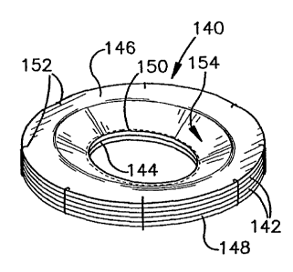
Fig. 11 illustrates another example of a meniscus prosthesis 140 in
accordance with an aspect of the present invention. The meniscus prosthesis
140 has a substantially annular cross-section and is formed of a plurality of
substantially coaxial layers 142 of a biocompatible tissue material. In
particular, the prosthesis 140 has a central aperture 144 extending through
the layers 142. Each layer 142 has a similar outer diameter and is generally
axially aligned and connected together, such as by sutures and/or a suitable
adhesive. For example, axially opposed end layers 146 and 148 of the
prosthesis 140 enclose one or more intermediate layers of material. Sutures
150 are applied near the inner diameter of the end layers 146 and 148 and
additional sutures 152 are applied near an outer periphery thereof.
As mentioned above in the example of Figs. 9 and 10, the inner
diameter of the component layers 142 may be dimensioned and configured so
that the thickness of the prosthesis 140 near the aperture 144 tapers radially
inwardly to a reduced thickness, which tapered portion is indicated at 154.
For example, the axial thickness of the prosthesis 140 at its inner diameter
may be defined by the axial thickness of the two outer layers or the two outer
layers 146 and 148. It is to be appreciated that one or more of the
intervening
layers also could be dimensioned to have an inner diameter so as to be
sandwiched between the outer layers 146 and 148.
The individual sheets 142, for example, are formed of animal
pericardial tissue, such as described hereinabove. It is to be appreciated
that
other tissue materials (e.g., natural or synthetic) also could be used in
accordance with the present invention.
Figs. 12 and 13 illustrates a meniscal prosthesis 200 implanted at a
knee joint 202 in accordance with an aspect of the present invention. The
12
CA 02427906 2003-05-09
WO 02/39889 PCT/USO1/47118
knee joint 202 includes femur 204 having a lateral condyle 206 and a medial
condyle 208. The prosthesis 200 is interposed between articulating surfaces
of a tibia 210 and the condyles 206 and 208. The prosthesis 200 helps
cushion between the articulating surfaces of the condyles 206 and 208 and
the tibia 210, such as during relative movement and/or stress between such
surfaces.
When implanting the prosthesis 200, it may be necessary to first cut
the bridge 216 so that the anterior cruciate ligament 218 may pass through a
triangular aperture 220 formed through the prosthesis. The bridge 216 may
be resecured to the prosthesis 200 (e.g., by sutures and/or adhesive) and, in
turn, provide a stabilizing function similar to the transverse ligament. An
opposed side of the prosthesis 200 has a recessed portion 222, which is
dimensioned and configured so as to not interfere with the posterior cruciate
ligament 224.
IS In view of the foregoing, the prosthesis 200 provides an elastic and
resilient support that exhibits desirable shock-absorbing properties and
biocompatibility. The amount of elasticity and resilience is proportional to
the
combined elasticity and resilience of the individual sheets that form the
prosthesis 200.
Fig. 14 illustrates another example of a meniscal prosthesis 250 in
accordance with an aspect of the present invention. In this example, the
prosthesis is formed of a molded protein that has been cross-linked with a
suitable aldehyde solution (e.g., glutaraldehyde) into a desired
configuration.
As mentioned above, the protein may be animal blood plasma, collagen,
fibrinogen, etc. After the cross-linked protein has a desired texture (e.g.,
generally resilient and elastic) and shape, it is detoxified, such as
according to
a NO-REACT~ detoxification treatment process. The resulting prosthesis 250
is a resilient elastic composite structure that provides desired shock-
absorbing
properties. In addition, the detoxification and cross-linking provide a
nonabsorbable prosthesis 250 that mitigates calcification as well as the
likelihood of rejection after being implanted in a human patient.
The illustrated configuration is substantially identical to that shown and
described with respect to Fig. 9 (except for the multiple layers in Fig. 9)
and,
13
CA 02427906 2003-05-09
WO 02/39889 PCT/USO1/47118
therefore, a detailed description of its configuration has been omitted for
purposes of brevity. Briefly stated, the prosthesis 250 includes a pair of
apertures 252 and 254 extending axially through the prosthesis according to
the location of a medial and lateral menisci of a patient. The diameter of
each
aperture at one side 256 of the prosthesis 250 is greater than the diameter of
the aperture at the other side 258 of the prosthesis.
Fig. 15 is another example of a meniscal prosthesis 270 having a
configuration similar to the example of Fig. 11. However, in this example, the
prosthesis 270 is formed from a molded protein structure that has been cross-
linked and detoxified as described herein. In particular, the prosthesis 270
is
molded to include an aperture 272 extending between opposed sides 274
and 276 of the prosthesis. The diameter of the aperture 272 at the side 274 is
greater than the diameter of the aperture at its opposed side 276, as shown in
Fig. 15. That is, the prosthesis 270 has a generally frusto-conical portion
278
1 S interconnecting the opposed sides 274 and 276.
What has been described above includes examples of the present
invention. It is, of course, not possible to describe every conceivable
combination of components or methodologies for purposes of describing the
present invention, but one of ordinary skill in the art will recognize that
many
further combinations and permutations of the present invention are possible.
Accordingly, the present invention is intended to embrace all such
alterations,
modifications and variations that fall within the spirit and scope of the
appended claims.
14