Note: Descriptions are shown in the official language in which they were submitted.
CA 02428100 2003-05-08
WO 02/45760 PCT/USO1/47549
DISTRIBUTION LAYER HAVING IMPROVED
LIQUID TRANSFER TO A STORAGE LAYER
FIELD OF THE INVENTION
The present invention relates to an cellulosic fibrous layer for distributing
acquired liquid to a storage layer in liquid communication therewith.
BACKGROUND OF THE INVENTION
Personal care absorbent products, for example, infant diapers, adult
incontinence
products, and feminine care products, can include liquid acquisition and/or
distribution
layers that serve to rapidly acquire and then distribute acquired liquid to a
storage core for
retention. To achieve rapid acquisition and distribution, these layers often
include
cellulosic fibers. These layers can include crosslinked cellulosic fibers to
impart bulk and
resilience to the layer, and wood pulp fibers to increase the wicking of
liquid within the
layer and to facilitate distribution of the liquid throughout the layer and
ultimately to
another layer, such as a storage layer, that is in liquid communication with
the
distribution layer. However, despite advances in these layers, the need exists
for a more
efficient liquid distribution layer that effectively distributes and transfers
acquired liquid
to an associated storage layer. The present invention seeks to fulfill these
needs and
provides further related advantages.
SUMMARY OF THE INVENTION
In one aspect, the present invention provides a fibrous layer that includes a
refined
blend of crosslinked cellulosic fibers and noncrosslinked cellulosic fibers.
In one
embodiment, the layer includes about 85 percent by weight crosslinked fibers
and about
15 percent by weight noncrosslinked fibers.
In another aspect of the invention, an absorbent construct is provided that
includes
a liquid distribution layer and a liquid storage layer. The distribution layer
includes a
refined blend of crosslinked cellulosic fibers and noncrosslinked cellulosic
fibers.
In other aspects, the invention provides personal care absorbent products that
include the distribution layer, and methods for making the distribution layer.
BRIEF DESCRIPTION OF THE DRAWINGS
The foregoing aspects and many of the attendant advantages of this invention
will
become more readily appreciated as the same become better understood by
reference to
-1-
CA 02428100 2003-05-08
WO 02/45760 PCT/USO1/47549
the following detailed description, when taken in conjunction with the
accompanying
drawings, wherein:
FIGURE 1 is a schematic diagram of a representative twin-wire forming device
and method for making a representative layer of the invention;
FIGURE 2 is a schematic diagram of a representative twin-wire forming device
and method for making a representative layer of the invention;
FIGURE 3 is a graph of wick time, dry tensile, and cantilever stiffness for a
representative layer of the invention;
FIGURE 4 is a graph of comparing fluid transfer for three representative
layers of
the invention to a storage layer as a function of time;
FIGURE 5 is a bar graph comparing the fourth gush acquisition time for
absorbent constructs: control training pant; control pant and representative
layer of the
invention; control pant with a storage core; and control pant, representative
layer of the
invention and storage core;
FIGURE 6 is a bar graph comparing the overall liquid capacity before leakage
for
absorbent constructs: control training pant; control pant and representative
layer of the
invention; control pant with a storage core; and control pant, representative
layer of the
invention and storage core;
FIGURE 7 illustrates the distribution of liquid in a training pant: control
training
pant; control pant and representative layer of the invention having a basis
weight of about
90 gsm; and control pant and representative layer of the invention having a
basis weight
of about 180 gsm;
FIGURE 8 illustrates the distribution of liquid in a training pant: control
training
pant; control pant with a storage core; control pant, storage layer, and
representative layer
of the invention having a basis weight of about 90 gsm; and control pant,
storage layer,
and representative layer of the invention having a basis weight of about 180
gsm
FIGURE 9 is a bar graph comparing the third gush acquisition rate for
absorbent
constructs: control training pant; control pant and representative layer of
the invention;
control pant with a storage core; and control pant, representative layer of
the invention
and storage core;
FIGURE 10 is a graph comparing acquisition rate as a function of insult number
for absorbent constructs: control training pant; control pant and
representative layer of
-2-
CA 02428100 2003-05-08
WO 02/45760 PCT/USO1/47549
the invention; control pant with a storage core; and control pant,
representative layer of
the invention and storage core;
FIGURE 11 is a bar graph comparing the fourth gush rewet for absorbent
constructs: control training pant; control pant and representative layer of
the invention;
control pant with a storage core; and control pant, representative layer of
the invention
and storage core;
FIGURES 12A-C illustrate cross-sectional views of portions of representative
absorbent constructs that include the distribution layer of the invention;
FIGURE 13A-D illustrate cross-sectional views of portions of representative
absorbent articles that include the distribution layer of the invention;
FIGURES 14A-F summarize the liquid uptake rate for representative distribution
layers of the invention;
FIGURE 15 summarizes the change in liquid uptake rate for representative
distribution layers of the invention;
FIGURES 16A-E summarize the liquid transfer to a storage core for
representative distribution layers of the invention;
FIGURES 17A-E summarize the liquid transfer to a storage core for
representative distribution layers of the invention;
FIGURES 18A-C summarize the liquid transfer to a storage core for
representative distribution layers of the invention;
FIGURE 19 is a graph illustrating distribution layer uptake rate as a function
of
basis weight;
FIGURE 20 is a graph illustrating transfer capacity for representative
distribution
layers of the invention;
FIGURE 21 is a graph illustrating transfer rate as a function of time for
representative distribution layers of the invention; and
FIGURE 22 is a graph illustrating the effect of wicking height on transfer
capacity
rate for representative distribution layers of the invention.
DETAILED DESCRIPTION OF THE PREFERRED EMBODIMENT
In one aspect, the present invention provides a cellulosic fibrous layer that
distributes and transfers liquid acquired by the layer to a storage layer that
is in liquid
communication therewith. The cellulosic fibrous layer of the invention is a
distribution
-3-
CA 02428100 2003-05-08
WO 02/45760 PCT/USO1/47549
layer that can be incorporated into a personal care absorbent product such as
an infant
diaper, adult incontinent product, or a feminine care product, among others.
In a personal
care absorbent product, the distribution layer can be used in combination with
one or
more other layers. Other layers can include, for example, a storage layer for
receiving
and storing liquid transferred from the distribution layer, or a storage layer
and an
acquisition layer.
The distribution layer of the invention includes cellulosic fibers. The
cellulosic
fibers are suitably wood pulp fibers. In one embodiment, the layer includes a
combination of crosslinked cellulosic fibers and noncrosslinked cellulosic
fibers.
The distribution layer's crosslinked cellulosic fibers impart bulk and
resilience to
the layer and provide the layer with a generally open structure for
distributing liquid.
Suitable crosslinlced cellulosic fibers include chemically intrafiber
crosslinked cellulosic
fibers and are described below. The layer includes crosslinked cellulosic
fibers in an
amount from about 50 to about 90 percent by weight based on the total weight
of fibers in
the layer. In one embodiment, the layer includes crosslinlced cellulosic
fibers in an
amount from about 75 to about 90 percent by weight based on the total weight
of fibers in
the layer. In another embodiment, the layer includes about 85 percent by
weight
crosslinked cellulosic fibers based on the total weight of fibers in the
layer. The layer can
include refined crosslinked fibers. The layer can include a refined blend of
crosslinked
and noncrosslinked fibers.
The distribution layer's noncrosslinked fibers enhance the layer's liquid
wicking
performance. Suitable noncrosslinked cellulosic fibers include wood pulp
fibers capable
of liquid wicking and are described below. The layer includes noncrosslinked
cellulosic
fibers in an amount from about 10 to about 50 percent by weight based on the
total
weight of fibers in the layer. In one embodiment, the layer includes
noncrosslinked
cellulosic fibers in an amount from about 10 to about 25 percent by weight
based on the
total weight of fibers in the layer. In another embodiment, the layer includes
about 15
percent by weight noncrosslinked cellulosic fibers based on the total weight
of fibers in
the layer. The noncrosslinked fibers can include softwood fibers (e.g.,
southern pine
fibers) and hardwood fibers (e.g., Westvaco hardwood fibers or eucalyptus
fibers).
In one embodiment, the layer includes southern pine pulp fibers commercially
available from Weyerhaeuser Company under the designation NB416. In another
-4-
CA 02428100 2003-05-08
WO 02/45760 PCT/USO1/47549
embodiment, the layer includes southern pine pulp fibers that have been
refined. In a
further embodiment, the layer includes eucalyptus pulp fibers. In another
embodiment,
the layer includes a blend of southern pine and eucalyptus fibers. In still
another
embodiment, the layer includes a blend of eucalyptus fibers and refined
southern pine
fibers. In yet a further embodiment, the layer includes a refined blend of
southern pine
and eucalyptus fibers.
For embodiments that include blends of southern pine and eucalyptus fibers,
the
ratio of southern pine fibers to eucalyptus fibers can range from about 0.5 to
about 1.0 to
about 1.0 to about 0.5. In one embodiment, the layer includes about 8 percent
by weight
eucalyptus fibers, about 7 percent by weight southern pine fibers, and about
85 percent by
weight crosslinked fibers based on the total weight of fibers in the layer. In
another
embodiment, the layer includes about 8 percent by weight eucalyptus fibers,
about 7
percent by weight refined southern pine fibers, and about 85 percent by weight
crosslinked fibers based on the total weight of fibers in the layer. In
another embodiment,
the layer includes a refined blend of eucalyptus and southern pine fibers, the
layer
including about 8 percent by weight eucalyptus fibers, about 7 percent by
weight southern
pine fibers, and about 85 percent by weight crosslinlced fibers based on the
total weight of
fibers in the layer. In yet another embodiment, the layer includes a refined
blend of
eucalyptus, southern pine, and crosslinked fibers, the layer including about 8
percent by
weight eucalyptus fibers, about 7 percent by weight southern pine fibers, and
about 85
percent by weight crosslinked fibers based on the total weight of fibers in
the layer.
In one embodiment, the distribution layer includes about 85 percent by weight
crosslinked fibers, from about 5 to about 15 percent by weight refined
southern pine
fibers having a Canadian Standard Freeness of about 500, and from about 0 to
about 10
percent by weight southern pine fibers. In one embodiment, the crosslinked
fibers,
refined southern pine fibers, and southern pine fibers are refined as a blend
prior to layer
formation.
In another embodiment, the distribution layer includes about 85 percent by
weight
crosslinked fibers, from about 3 to about 5 percent by weight hardwood fibers,
and from
about 10 to about 12 percent by weight southern pine fibers. In one
embodiment, the
crosslinked fibers, hardwood fibers, and southern pine fibers are refined as a
blend prior
to layer formation.
-5-
CA 02428100 2003-05-08
WO 02/45760 PCT/USO1/47549
In one embodiment, the distribution layer has a basis weight in the range from
about 20 to about 200 glm2. In another embodiment, the distribution layer has
a basis
weight in the range from about 50 to about 180 g/m2. The distribution layer
has a density
in the range from about 0.1 to about 0.2 g/cm3.
The characteristics of four representative distribution layers are summarized
in
Tables 1 and 2 below. In Tables 1 and 2, unsoftened Layer A includes a refined
blend of
crosslinked fibers (85 percent by weight polyacrylic acid crosslinked fibers)
and southern
pine fibers (15 percent by weight refined fibers, 500 CSF); unsoftened Layer B
includes a
refined blend of crosslinked fibers (80 percent by weight polyacrylic acid
crosslinked
fibers) and southern pine fibers (20 percent by weight refined fibers, 500
CSF);
unsoftened Layer C includes a refined blend of crosslinked fibers (85 percent
by weight
DMeDHEU crosslinked fibers, commercially available from Weyerhaeuser Co. under
the
designation NHB 416) and southern pine fibers (15 percent by weight refined
fibers, 500
CSF); and softened (embossed) Layer D includes a refined blend of crosslinked
fibers (85
percent by weight DMeDHEU crosslinked fibers) and southern pine fibers (15
percent by
weight refined fibers, 500 CSF). As used herein, the term "unsoftened" refers
to a layer
that has not been subjected to mechanical treatment, such as, for example,
calendering,
tenderizing, or embossing. The data presented in Table 1 was acquired using a
TRI
Autoporosimeter Device.
-6-
CA 02428100 2003-05-08
WO 02/45760 PCT/USO1/47549
Table 1. Performance Characteristics of Representive Distribution Layers.
Layer Ring MD,CD Peak MDP:MAP* MDP* MAP* MUP* Surface
CrushGurley GeometricRatio Tension
(g) Stiffness Mean Tensile (dynes/cm)
SGU/mm ( /cm)
A 3405 1137 , 858.0 1.81:1 24.2 13.4 10.0 6S.S
S62
B 1500 6S0 , 266 763.5 1.72:1 22.1 12.9 9.5 69.6
C 1500 623 , 390 725.5 1.91:1 29.0 15.2 9.2 66.8
D 900 351 , 163 S46.S L98:1 28.5 14.4 8.I 66.8
Table 2. Performance Characteristics of Representive Distribution Layers.
Layer Ave. Ave. WickingWicking Wicking MD,CD MD,CD
0.D. A.D. Time Height CapacityTensileElongation
Basis Basis to at 15 min at (g/cm) (%)
Weight Weight 1S cm (cm) 1S cm
( sm) ( sm) (sec) after
1S min
( /
)
A 88 0.114 174 21.8 8.6 1020, 2.6, S.6
696
B 52 0.117 291 19.8 7.3 952, 2.4, 4.1
S7S
C S3 0.126 277 19.2 7.7 899, 2.7, 3.8
SS2
D S3 0.165 326 18.6 7.5 ~ 651, 2.8, S.1
442
In addition to cellulosic fibers, the distribution layer can include a wet
strength
agent. Suitable wet strength agents are described below. The wet strength
agent is
present in the layer in an amount from about 5 to about 20 pounds/ton fiber.
In one
embodiment, the wet strength agent is a polyamide-epichlorohydrin resin
present in the
layer in about 10 pounds/ton fiber.
As noted above, the distribution layer of the invention includes crosslinked
cellulosic fibers. Any one of a number of crosslinking agents and crosslinking
catalysts,
if necessary, can be used to provide the crosslinked fibers to be included in
the layer. The
following is a representative list of useful crosslinking agents and
catalysts. Each of the
patents noted below is expressly incorporated herein by reference in its
entirety.
CA 02428100 2003-05-08
WO 02/45760 PCT/USO1/47549
Suitable urea-based crosslinking agents include substituted ureas such as
methylolated ureas, methylolated cyclic ureas, methylolated lower alkyl cyclic
ureas,
methylolated dihydroxy cyclic ureas, dihydroxy cyclic ureas, and lower alkyl
substituted
cyclic ureas. Specific urea-based crosslinking agents include
dimethyldihydroxy urea
(DMDHLT, 1,3-dimethyl-4,5-dihydroxy-2-imidazolidinone),
dimethyloldihydroxyethylene urea (DMDHEU, 1,3-dihydroxymethyl-4,5-dihydroxy-2-
imidazolidinone), dimethylol urea (DMLT, bis[N-hydroxymethyl]urea),
dihydroxyethylene urea (DHEU, 4,5-dihydroxy-2-irnidazolidinone),
dimethylolethylene
urea (DMEU, 1,3-dihydroxymethyl-2-imidazolidinone), and
dimethyldihydroxyethylene
urea (DMeDHEU or DDI, 4,5-dihydroxy-1,3-dimethyl-2-imidazolidinone).
Suitable crosslinking agents include dialdehydes such as C2-C8 dialdehydes
(e.g.,
glyoxal), C2-Cs dialdehyde acid analogs having at least one aldehyde group,
and
oligomers of these aldehyde and dialdehyde acid analogs, as described in U. S.
Patents
Nos. 4,822,453; 4,888,093; 4,889,595; 4,889,596; 4,889,597; and 4,898,642.
Other
suitable dialdehyde crosslinking agents include those described in U.S.
Patents Nos.
4,853,086; 4,900,324; and 5,843,061.
Other suitable crosslinking agents include aldehyde and urea-based
formaldehyde
addition products. See, for example, U.S. Patents Nos. 3,224,926;
3,241,533;'3,932,209;
4,035,147; 3,756,913; 4,689,118; 4,822,453; 3,440,135; 4,935,022; 3,819,470;
and
3,658,613.
Suitable crosslinlcing agents include glyoxal adducts of ureas, for example,
U.S.
Patent No. 4,968,774, and glyoxal/cyclic urea adducts as described in U.S.
Patents
Nos. 4,285,690; 4,332,586; 4,396,391; 4,455,416; and 4,505,712.
Other suitable crosslinking agents include carboxylic acid crosslinking agents
such as polycarboxylic acids. Polycarboxylic acid crosslinking agents (e.g.,
citric acid,
propane tricarboxylic acid, and butane tetracarboxylic acid) and catalysts are
described in
U.S. Patents Nos. 3,526,048; 4,820,307; 4,936,865; 4,975,209; and 5,221,285.
The use of
CZ-C9 polycarboxylic acids that contain at least three carboxyl groups (e.g.,
citric acid and
oxydisuccinic acid) as crosslinking agents is described in U.S. Patents Nos.
5,137,537;
5,183,707; 5,190,563; 5,562,740, and 5,873,979.
Polymeric polycarboxylic acids are also suitable crosslinking agents. Suitable
polymeric polycarboxylic acid crosslinking agents are described in U. S.
Patents
_g_
CA 02428100 2003-05-08
WO 02/45760 PCT/USO1/47549
Nos.4,391,878; 4,420,368; 4,431,481; 5,049,235; 5,160,789; 5,442,899;
5,698,074;
5,496,476; 5,496,477; 5,728,771; 5,705,475; and 5,981,739. Polyacrylic acid
and related
copolymers as crosslinking agents are described U.S. Patents Nos. 5,549,791
and
5,998,511. Polymaleic acid crosslinking agents are described in U.S. Patent
No.
5,998,511.
Specific suitable polycarboxylic acid crosslinking agents include citric acid,
tartaric acid, malic acid, succinic acid, glutaric acid, citraconic acid,
itaconic acid, tartrate
monosuccinic acid, malefic acid, polyacrylic acid, polymethacrylic acid,
polymaleic acid,
polymethylvinylether-co-maleate copolymer, polymethylvinylether-co-itaconate
copolymer, copolymers of acrylic acid, and copolymers of malefic acid.
Other suitable crosslinking agents are described in U.S. Patents Nos.
5,225,047;
5,366,591; 5,556,976; and 5,536,369.
Suitable catalysts can include acidic salts, such as ammonium chloride,
ammonium sulfate, aluminum chloride, magnesium chloride, magnesium nitrate,
and
alkali metal salts of phosphorous-containing acids. In one embodiment, the
crosslinking
catalyst is sodium hypophosphite.
Mixtures or blends of crosslinlcing agents and catalysts can also be used.
The crosslinking agent is applied to the cellulosic fibers in an amount
sufficient to
effect intrafiber crosslinking. The amount applied to the cellulosic fibers
can be from
about 1 to about 10 percent by weight based on the total weight of fibers. In
one
embodiment, crosslinking agent in an amount from about 4 to about 6 percent by
weight
based on the total weight of fibers.
In addition to crosslinked fibers, the distribution layer of the invention
also
includes noncrosslinked cellulosic fibers. Suitable cellulosic fibers include
those known
to those skilled in the art and include any fiber or fibrous mixture from
which a fibrous
web or sheet can be formed.
Although available from other sources, cellulosic fibers are derived primarily
from wood pulp. Suitable wood pulp fibers for use with the invention can be
obtained
from well-known chemical processes such as the kraft and sulfite processes,
with or
without subsequent bleaching. Pulp fibers can also be processed by
thermomechanical,
chemithermomechanical methods, or combinations thereof. The preferred pulp
fiber is
produced by chemical methods. Groundwood fibers, recycled or secondary wood
pulp
-9-
CA 02428100 2003-05-08
WO 02/45760 PCT/USO1/47549
fibers, and bleached and unbleached wood pulp fibers can be used. Softwoods
and
hardwoods can be used. Details of the selection of wood pulp fibers are well
known to
those skilled in the art. These fibers are commercially available from a
number of
companies, including Weyerhaeuser Company, the assignee of the present
invention. For
example, suitable cellulose fibers produced from southern pine that are usable
with the
present invention are available from Weyerhaeuser Company under the
designations
CF416, NF405, PL416, FR516, and NB416.
The wood pulp fibers useful in the present invention can also be pretreated
prior
to use. This pretreatment may include physical treatment, such as subjecting
the fibers to
steam, or chemical treatment. Other pretreatments include incorporation of
antimicrobials, pigments, dyes and densification or softening agents. Fibers
pretreated
with other chemicals, such as thermoplastic and thermosetting resins also may
be used.
Combinations of pretreatments also may be employed. Treatments can also be
applied
after formation of the fibrous product in post-treatment processes, examples
of which
include the application of surfactants or other liquids, which modify the
surface chemistry
of the fibers, and the incorporation of antimicrobials, pigments, dyes, and
densification or
softening agents. -
The distribution layer optionally includes a wet strength agent. Suitable wet
strength agents include cationic modified starch having nitrogen-containing
groups (e.g.,
amino groups) such as those available from National Starch and Chemical Corp.,
Bridgewater, NJ; latex; wet strength resins, such as polyamide-epichlorohydrin
resin
(e.g., KYMENE 557LX, Hercules, Inc., Wilmington, DE), and polyacrylamide resin
(see,
e.g., U.S. Patent No. 3,556,932 and also the commercially available
polyacrylamide
marketed by American Cyanamid Co., Stanford, CT, under the trade name PAREZ
631
NC); urea formaldehyde and melamine formaldehyde resins; and polyethylenimine
resins. A general discussion on wet strength resins utilized in the paper
field, and
generally applicable in the present invention, can be found in TAPPI monograph
series
No. 29, "Wet Strength in Paper and Paperboard", Technical Association of the
Pulp and
Paper Industry (New York, 1965).
In another aspect of the invention, methods for forming the distribution layer
are
provided. Representative distribution layers can be formed using conventional
-10-
CA 02428100 2003-05-08
WO 02/45760 PCT/USO1/47549
papermaking machines including, for example, Rotoformer, Fourdrinier, inclined
wire
Delta former, and twin-wire machines.
The layer can be formed by devices and processes that include a twin-wire
configuration (i.e., twin-forming wires). Representative forming methods
applicable for
forming the distribution layer of the invention are described in
PCT/LTS99/05997
(Method for Forming a Fluted Composite) and PCT/LTS99/27625 (Reticulated
Absorbent
Composite), each incorporated herein by reference in its entirety. A
representative twin-
wire machine for forming the layer is shown in FIGURE 1. Referring to FIGURE
l,
machine 200 includes twin-forming wires 202 and 204 onto which the layer's
components
are deposited. Basically, fibrous slurry 124 is introduced into headbox 212
and deposited
onto forming wires 202 and 204 at the headbox exit. Vacuum elements 206 and
208
dewater the fibrous slurries deposited on wires 202 and 204, respectively, to
provide
partially dewatered webs that exit the twin-wire portion of the machine as
partially
dewatered web 126. Web 126 continues to travel along wire 202 and continues to
be
dewatered by additional vacuum elements 210 to provide wet composite 120 which
is
then dried by drying means 216 to provide layer 10.
In one embodiment, the composite is formed by a wetlaid process using the
components described above. The wetlaid method can be practiced on an inclined
wire
Delta former. In another embodiment, the composite is formed by a foam-forming
method using the components described above. Wetlaid and foam-forming
processses
can be practiced on a twin-wire former.
A representative method for forming a distribution layer of the invention
includes
the following steps:
(a) forming a fibrous slurry comprising fibers in an aqueous dispersion
medium; for a foam method, the slurry is a foam that includes, in addition to
fibers, a
surfactant;
(b} moving a first foraminous element (e.g., a forming wire) in a first path;
(c) moving a second foraminous element in a second path;
(d) passing a first portion of the slurry into contact with the first
foraminous
element moving in a first path;
(e) passing a second portion of the slurry into contact with the second
foraminous element moving in the second path; and
-11-
CA 02428100 2003-05-08
WO 02/45760 PCT/USO1/47549
forming a fibrous web from the slurry by withdrawing liquid from the
slurry through the first and second foraminous elements.
As noted above, the foam-forming method is suitably carried out on a twin-wire
former, preferably a vertical former, and more preferably, a vertical downflow
twin-wire
former. In the vertical former, the paths for the foraminous elements are
substantially
vertical.
A representative vertical downflow twin-wire former useful in practicing a
method of the invention is illustrated in FIGURE 2. Referring to FIGURE 2, the
former
includes a vertical headbox assembly having a former with a closed first end
(top), closed
first and second sides and an interior volume. A second end (bottom) of the
former is
defined by moving first and second foraminous elements, 202 and 204, and
forming
nip 213. The interior volume defined by the former's closed first end, closed
first and
second sides, and first and second foraminous elements includes an interior
structure 230
extending from the former first end and toward the second end. The interior
structure
defines a first volume 232 on one side thereof and a second volume 234 on the
other side
thereof. The former further includes supply 242 and means 243 for, introducing
a first
fiber/foam slurry into the first volume, supply 244 and means 245 for
introducing a
second fiber/foam slurry into the second volume, and supply 246 and means 247
for
introducing a third material (e.g., the first or second fiber/foam slurry)
into the interior
structure. Means for withdrawing liquid/foam (e.g., suction boxes 206 and 208)
from the
first and second slurries through the foraminous elements to form a web are
also included
in the headbox assembly.
In the method, the twin-wire former includes a means for introducing at least
a
third material (e.g., the first or second fiber/foam slurry) through the
interior structure.
The first and second fiber/foam slurries can include the same components
(e.g.,
crosslinl~ed cellulosic fibers, southern pine fibers, eucalyptus fibers) and
have the same
composition.
Depending upon the nature of the composite to be formed, the first and second
fiber/foam slurries may be the same as or different from each other, and the
same as or
different from a third material.
The means for withdrawing liquid/foam from the first and second slurries
through
the foraminous elements to form a web on the foraminous elements are also
included in
-12-
CA 02428100 2003-05-08
WO 02/45760 PCT/USO1/47549
the headbox assembly, The means for withdrawing liquid/foam can include any
conventional means for that purpose, such as suction rollers, pressing
rollers, or other
conventional structures. In a preferred embodiment, first and second suction
box
assemblies are provided and mounted on the opposite sides of the interior
structure from
the foraminous elements (see boxes 206 and 208 in FIGURES 1 and 2).
The distribution layer of the invention advantageously exhibits strength
(e.g.,
structural integrity) and softness. In addition to having flexibility and
softness suitable
for incorporation into personal care absorbent products, the composites of the
invention
exhibit advantageous structural integrity. Structural integrity can be
indicated by tensile
strength. Suitable layers have a tensile strength greater than about 10 N/50
mm.
Suitable layers have a machine direction (MD) tear strength greater than about
205 mN, and a cross-machine direction (CD) tear strength greater than about
260 mN.
The tear strength of representative distribution layers of the invention was
determined by
ASTM Method No. P-326-5. In the method, the machine direction (MD) and cross-
machine direction (CD) tear strengths of 10 specimens of representative layers
(1-3 in
Table 1 below) were measured. Layer 1 included 85 percent by weight
crosslinked
fibers, 8 percent by weight eucalyptus fibers, and 7 percent by weight
southern pine
fibers. Layer 2 included 85 percent by weight crosslinked fibers, .8 percent
by weight
eucalyptus fibers, and 7 percent by weight refined southern pine fibers. Layer
3 included
85 percent by weight crosslinked fibers, 8 percent by weight hardwood fibers
(Westvaco),
and 7 percent by weight refined southern pine fibers. The average, maximum,
minimum
tear strengths as well as their ranges (mN) are summarized in Table 3.
Table 3. Representative Distribution Layer Tear Strength.
La er Avera a Maximum Minimum Ran a
1 (MD) 242.2 284.4 215.7 68.6
1 (CD) 322.6 362.8 304.0 58.8
2 (MD) 419.7 431.5 402.1 29.4
2 (CD) 531.5 559.0 490.3 68.6
3 (MD) 388.3 431.5 362.8 68.6
3 (CD) 514.8 588.4 460.9 127.5
-13-
CA 02428100 2003-05-08
WO 02/45760 PCT/USO1/47549
Extracts of suitable layers have a surface tension greater than about 50
dynes/cm.
The method for determining the surface tension of a pulp extract is described
below.
Suitable layers have a softness, as measured by ring crush, less than about
1200 g.
The distribution layer of the invention exhibits advantageous fluidic
properties.
The properties can be indicated by various measures including liquid
acquisition rate,
rewet, wicking, rnid-point desorption pressure, mid-point acquisition
pressure, and mid-
point uptake.
The layer has a mid-point desorption pressure (MDP) greater than about 20 cm.
In one embodiment, the layer has a MDP greater than about 30 cm. In another
embodiment, the layer has a MDP greater than about 40 cm.
The layer has a mid-point acquisition pressure (MAP) less than about 25 cm. In
one embodiment, the layer has a MAP less than about 20 cm.
The layer has a mid-point uptake (MU) greater than about 5 g/g.
A description of the method for determining MDP, MAP, and MU is provided in
1 S Liquid Porosimetry: New Methodology and Applications, B. Miller and I.
Tomkin,
Journal of Colloid Interface Science, 162:163-170, 1994, incorporated herein
by
reference in its entirety.
Liquid transfer rate was determined by soaking a strip of representative
distribution layer (10 cm width) with synthetic urine. The soaked layer was
allowed to
drain for 3 minutes on the test device. The test device on which the layer was
placed
included a horizontal surface adjacent a 60 degree sloped surface (i.e., a
ramp). The
distribution layer extended across the horizontal and sloped portions of the
device with
one end terminating in a reservoir containing a known amount of synthetic
urine. The
horizontal surface was 11 cm above the lower edge of the sloped surface. A
receiving
layer (e.g., storage layer, 10 cm x 10 cm) was placed on top of the
distribution layer on
the horizontal surface. A weight (704 g, 10 cm x 10 cm delivering 0.10 psi)
was placed
on top of the receiving layer. The receiving layer was allowed to absorb for
20 minutes
against the 15 cm head. The amount of liquid transferred from the reservoir
was
measured and the transfer rate calculated.
The layer of the invention provides a liquid transfer rate greater than zero
at a
wicking height of 11 cm when incorporated as the distribution layer into a
commercial
infant diaper (PAMPERS).
-14-
CA 02428100 2003-05-08
WO 02/45760 PCT/USO1/47549
Other physical and performance characteristics of representative distribution
layers of the invention (Layers 4-8) are summarized in Table 4 below. Layer 4
included
85 percent by weight crosslinked fibers, 8 percent by weight eucalyptus
fibers, and 7
percent by weight southern pine fibers. Layers 5-8 were derived from Layer 4
by
softening under varying conditions (4, 12, 16, and 17, respectively) as
described below in
Table 4. Layer 5 was softened by applying a pressure of 35 bar with a cold
calender roll;
Layer 6 was softened by applying a pressure of 35 bar with a cold calender
roll and 2 bar
in the layer's machine direction; Layer 7 was softened by applying a pressure
of 35 bar
with a cold calender roll and embossing the top and bottom surfaces of the
layer (2
passes) at a pressure of 8 bar; and Layer 8 was softened by applying a
pressure of 8 bar to
the layer's machine and cross-machine directions.
-15-
CA 02428100 2003-05-08
WO 02/45760 PCT/USO1/47549
Table 4. Representative Distribution Layer Physical and Performance
Characteristics.
Distribution La er 4 5 6 7 8
Test
Ca so tion
MDP (cm) 32.2 44.2 43.5 42 35.3
MAP (cm) 17.5 23.6 22.3 22.3 18.8
MU (g/g) 7 5.4 5.8 5.3 6.8
Softness (rin crusli,2700 1070 320 330 250
g)
Tensile (N/50mm) 29.2 20.8 12.2 8.9 2.3
Surface tension 48 53 52 52 53
Briglitness 72.2 73.7 73.7 74.1 73.1
Basis wei lit (g/m')152 152 153 153 137
Cali er (mm) 1.29 0.54 0.77 0.72 1.30
Densi ( /cm3) 0.118 0.283 0.200 0.212 0.105
Wickin time to 15 273 238 240 248 710
cm (sec)
Wick ca aci (a7 15 6.6 6 ' 6.2 6.4 7.1
cm (g/ )
Wicked Ht. 15 min 19.2 21 21.2 20.2 15.2
(cm)
Softness
Cantilever Stiffness,107 59 53 41 39
MD (mm)
Cantilever Stiffness,83 51 29 27 37
CD (mm)
Stren
Dry Tensile, MD (N/50mm)29.2 20.8 12.2 8.9 2.3
-16-
CA 02428100 2003-05-08
WO 02/45760 PCT/USO1/47549
Dry EIon . (mm) 4.3 4.9 5.5 6.5 9.7
Dry Elon . (%) 2.1 2. S 2.7 3.2 4. 8
Wet Tensile, MD (N/SOmm)8.9 5.I 3.4 2.1 0.7
Wet Elon . (mm) 11.3 12.4 13.3 13.1 10.4
Wet Elon . (%) 5.7 6.2 6.7 6.6 5.2
Wet Stren i (W/D%) 31 25 28 24 28
Ca aci ( / ad) 3.8 3.6 3.6 3.8 3.7
Wick time and tensile versus cantilever stiffness for Layers 4-8 is
illustrated
graphically in FIGURE 3.
Fluid transfer to core versus time far Layers 4, S, and 8 is illustrated
graphically in
FIGURE 4.
The distribution layer formed in accordance with the present invention can be
incorporated into an absorbent article such as a diaper. The composite can be
used alone
or combined with one or more other layers, such as acquisition and/or storage
layers, to
provide useful absorbent constructs.
Representative absorbent constructs that incorporate the distiribution layer
are
illustrated in FIGURES 12A-C. Referring to FIGURE 12A, representative
distribution
layer 10 can be combined with a storage layer 20 to provide construct 100.
Referring to
FIGURE 12B, acquisition layer 30 can be combined with distribution layer 10
and
storage layer 20 to provide construct 110 having distribution layer 10
intermediate
acquisition layer 30 and storage layer 20. Referring to FTGURE 12C,
acquisition layer 30
can be combined with distribution layer 10 and storage layer 20 to provide
construct 120
having storage layer 20 intermediate acquisition layer 30 and distribution
layer 10.
As noted above, the distribution layer can be incorporated into personal care
absorbent products, such as infant diapers, training pants, and incontinence
products.
Representative absorbent articles that incorporate the distribution layer are
illustrated in
FIGURES 13A-D. In general, the absorbent articles include an absorbent
construct
intermediate a liquid pervious face sheet and a liquid impervious baclc sheet.
Typically,
in such absorbent articles, the face sheet is joined to the back sheet.
Referring to
-17
CA 02428100 2003-05-08
WO 02/45760 PCT/USO1/47549
FIGURE 13A, article 200 includes face sheet 40, distribution layer 10, storage
layer 20,
and back sheet S0. In this article, distribution layer 10 is adjacent face
sheet 40.
Referring to FIGURE 13B, article 205 includes face sheet 40, storage layer 20,
distribution layer 10, and back sheet 50 with distribution layer 10 adjacent
back sheet 50.
Referring to FIGURE 13C, article 210 includes face sheet 40, acquisition layer
30,
distribution layer 10, storage layer 20, and back sheet 50. In this article,
distribution layer
is intermediate acquisition layer 30 and storage layer 20. Referring to FIGURE
13D,
article 220 includes face sheet 40, acquisition layer 30, storage layer 20,
distribution layer
10, and back sheet 50. In this article, distribution layer 10 is adjacent back
sheet 50.
10 It will be appreciated that absorbent constructs and articles that include
the
distribution layer of the invention can have a vareity of designs and are
within the scope
of this invention.
The distribution layer was tested in training pants.
In the following tests the training pants contain SAP. As used herein, a SAP
or
"superabsorbent particles" or "superabsorbent material" refers to a polymeric
material
that is capable of absorbing large quantities of fluid by swelling and forming
a hydrated
gel (i.e., a hydrogel). In addition to absorbing large quantities of fluids,
superabsorbent
materials can also retain significant amounts of bodily fluids under moderate
pressure.
Superabsorbent materials generally fall into three classes: starch graft
copolymers, crosslinked carboxymethylcellulose derivatives, and modified
hydrophilic
polyacrylates. Examples of such absorbent polymers include hydrolyzed starch
acrylonitrile graft copolymers, neutralized starch-acrylic acid graft
copolymers,
saponified acrylic acid ester-vinyl acetate copolymers, hydrolyzed
acrylonitrile
copolymers or acrylamide copolymers, modified crosslinked polyvinyl alcohol,
neutralized self crosslinking polyacrylic acids, crosslinked polyacrylate
salts,
carboxylated cellulose, and neutralized crosslinked isobutylene-malefic
anhydride
copolymers.
Superabsorbent materials are available commercially, for example,
polyacrylates
from Clariant of Portsmouth, Virginia. These superabsorbent polymers come in a
variety
of sizes, morphologies, and absorbent properties (available from Clariant
under trade
designations such as IM 3500 and IM 3900). Other superabsorbent materials are
marketed under the trademarks SANWET (supplied by Sanyo Kasei Kogyo Kabushiki
-18
CA 02428100 2003-05-08
WO 02/45760 PCT/USO1/47549
Kaisha), and SXM77 (supplied by Stockhausen of Greensboro, North Carolina).
Other
superabsorbent materials are described in U.S. Patent No.4,160,059; U.S.
Patent
No.4,676,784; U.S. Patent No.4,673,402; U.S. Patent No. 5,002,814; U.S. Patent
No. 5,057,166; U.S. Patent No. 4,102,340; and U.S. Patent No. 4,818,598, all
expressly
incorporated herein by reference. Products such as diapers that incorporate
superabsorbent materials are described in U.S. Patent No. 3,699,103 and U.S.
Patent
No. 3,670,731.
The first control training pant was a large "Members Mark" Kids Pants (Paragon
Training Pant) which has a storage core containing approximately 46% SAP. The
storage
core has a capacity of approximately 380 mls (milliliters) of urine. The core
contains 13
grams of SAP mixed with 15 grams of airlaid fluff pulp.
This control was compared to two test training pants. Each of the test
training
pants used the same control training pant. In each of the test training pants
a distribution
layer was placed under the storage core.
In the first test training pant, also called Paragon Training Pant with UDL
1049-5,
the UDL distribution layer had a weight of 180 gsm (grams per square meter)
and a
capacity of 48 mls of urine. It contained 8 grams of fiber.
In the second test pant, also called Paragon Training Pant with UDL 1081-8,
the
UDL distribution layer had a weight of 90 gsm and a capacity of 24 mls of
urine. It
contained 4 grams of fiber.
The second control training pant was a large "Members Mark" Kids Pants
(Paragon Training Pant with 70% core) which has a storage core containing
approximately 70% SAP. The storage core has a capacity of approximately 320
mls of
urine. The core contains 13 grams of SAP mixed with 5.5 grams of airlaid
treated fluff
pulp. The pulp was mixed with a mixture of equal molecular amounts of
propylene
glycol, lactic acid and sodium lactate. The amount of the mixture on the pulp
was 7-9%
of the weight of the pulp.
This control was also compared to two test training pants. Each of the test
training pants used the same control training pant. In each of the test
training pants a
distribution layer was placed under the storage core.
-19-
CA 02428100 2003-05-08
WO 02/45760 PCT/USO1/47549
In the first test training pant, also called Paragon Training Pant with 70%
core and
LJDL 1049-5, the UDL distribution layer had a weight of 180 gsm and a capacity
of 48
mls of urine. It contained 8 grams of fiber.
In the second test pant, also called Paragon Training Pant with 70% core and
UDL
1081-8, the UDL distribution layer had a weight of 90 gsm and a capacity of 24
mls of
urine. It contained 4 grams of fiber.
Saddle Wicking Test
Saddle wicking, including acquisition rate, distribution, and wicking height,
was
determined by the method described below.
Procedure:
1) Draw and label the 6 even cells using a template and a permanent marker.
2) Place an "X" at the midpoint of the line between the 3rd and 4th cells.
3) Position diaper in Saddle Device so that the "X" is squarely at the bottom
of the apparatus and then position a 250 ml separatory funnel
approximately 1 cm directly above the "X."
4) Measure out 75m1 of synthetic urine (Blood Bank 0.9% saline) and pour
into funnel.
5) Open the funnel and start the timer. Measure the time at which all of the
fluid has left the funnel to the point where the fluid is absorbed into the
sample. Record as acquisition time.
6) Repeat steps 7 and 8 every 20 minutes, until the training pant Leaks (Free
fluid in training pant 20 minutes after the insult or fluid addition)
7) When the diaper has leaked extract the free fluid out of the training pant
using a syringe.
8) Measure and record the amount of free.fluid extracted in step 7.
9) Pull out training pant and cut sample into designated cells.
10) Weigh each cell and record the wet weight.
11) Place each cell into oven to dry.
12) Weigh and record dry weights of each cell.
13) Calculate the amount of fluid in each cell (wet weight - dry weight).
14) Calculate the capacity utilized before leakage ((number of insults x 75m1)
- free fluid extracted).
-20-
CA 02428100 2003-05-08
WO 02/45760 PCT/USO1/47549
The results of the saddle wicking tests are shown in FIGURES 5 through 11.
FIGURE 5 shows the time in seconds to acquire fluid during the 4~' insult for
the control
and test training pants, and demonstrates the effectiveness of the UDL in
transferring
fluid so the core can acquire fluid more rapidly. FIGURE 6 shows the total
fluid
absorbed in milliliters before leakage occurred. FIGURES 7 and 8 show the
distribution
of fluid in grams in each of the zones of the training pant.
Market Pulp Flat Acquisition Test
Acquisition time and rewet were obtained for the control and test training
pants.
The acquisition time and rewet are determined in accordance with the multiple-
dose rewet test described below.
Briefly, the multiple-dose rewet test measures the amount of synthetic urine
released from an absorbent structure after each of three liquid applications,
and the time
required for each of the three liquid doses to wick into the product.
The aqueous solution used in the tests was a synthetic urine made up of one
part
synthetic urine concentrate and nine parts deionized water..
The training pant was clamped onto a clampboard, fully extended, with the
nonwoven side up. The training pant was prepared for the test by determining
the center
of the structure's core, measuring 2.5 cm. to the front for liquid application
location, and
marking the location with an "X". A dosing ring (5/32 inch stainless steel, 2
inch ID x 3
inch height) was placed onto the "X" marked on the samples. A liquid
application funnel
(minimum 100 mL capacity, 5-7 mL/s flow rate) was placed 2-3 cm. above the
dosing
ring at the "X". Once the sample was prepared, the test was conducted as
follows.
The funnel was filled with a dose (75 mL) of synthetic urine. A first dose of
synthetic urine was applied within the dosing ring. Using a stopwatch, the
liquid
acquisition time was recorded in seconds from the time the funnel valve was
opened until
the liquid wicked into the product from the bottom of the dosing ring. The
acquisition
rate was determined by dividing the amount of synthetic urine (75 ml) by the
acquisition
time to obtain the acquisition rate in grams per second. A milliliter of
synthetic urine is
equal to 1 gram.
After a twenty-minute wait period, rewet was determined. During the twenty-
minute wait period after the first dose was applied, a stack of filter papers
(19-22 g,
Whatman #3, 11.0 cm or equivalent, that had been exposed to room humidity for
-21-
CA 02428100 2003-05-08
WO 02/45760 PCT/USO1/47549
minimum of 2 hours before testing) was weighed. The stack of preweighed filter
papers
was placed on the center of the wetted area. A cylindrical weight (8.9 cm
diameter,
9.8 1b.) was placed on top of these filter papers. After two minutes the
weight was
removed, the filter papers were weighed and the weight change recorded.
The procedure was repeated two more times. Another 75m1 dose of synthetic
urine was added to the diaper, and the acquisition time and rate was
determined, filter
papers were placed on the sample for two minutes, and the weight change
determined.
For the second dose, the weight of the dry filter papers was 29-32 g, and for
the third
dose, the weight of the filter papers was 39-42 g. The dry papers from the
prior dosage
were supplemented with additional dry filter papers.
FIGURE 9 shows the acquisition rate of the 3rd insult in grams per second.
FIGURE 10 shows the acquisition rate for three successive insults in grams per
second.
Rewet is reported as the amount of liquid (grams) absorbed back into the
filter
papers after each liquid dose (i.e., difference between the weight of wet
filter papers and
the weight of dry filter papers). FIGURE 11 shows the rewet after the 4~
insult.
Pulp Extract Surface Tension Method
The following method is used to determine the surface tension of pulp
extracts. In
the method, pulp fibers are mixed with water to extract residue and
contaminants. The
surface tension of the filtrate is measured to demonstrate the surface
activity of the
extractives and their relative concentration on the pulp fibers. The procedure
is described
below.
A. Wearing gloves to prevent contamination, remove a 2.0 gram subsample
of pulp from a pulp sheet and place in a clean, dry 125-mL Nalgene bottle.
B. Add 100 mL of deionized water and cap the bottle tightly.
C. Place the bottle on a wrist action shaker and shake on high intensity for 1
hour.
D. Remove the bottle from the shaker and allow to stand for 10 minutes. This
helps to separate the fibers from the water before filtering.
E. Assemble a filtration apparatus using a clean, dry 125-mL Nalgene bottle
inside a filter box with an 11.0 cm Buchner funnel placed on top. Place an
11.0 cm
Whatman grade #4 filter paper in the Buchner funnel. An equivalent filter can
be used if
-22-
CA 02428100 2003-05-08
WO 02/45760 PCT/USO1/47549
it has the following specifications: fast qualitative type, 12 sec./100 mL
filtration speed,
0.06% ash content, and 20-25 ~, particle size retention.
F. Attach the filter assembly to a standard (25 in. of Hg) vacuum system.
G. Turn on the vacuum system, uncap the sample bottle, and pour the
contents onto the filter in the Buchner funnel. All the filtrate should be
removed from the
pulp fibers in 15-30 seconds.
H. Turn off the vacuum system and remove the collection bottle from the
filter box. Swirl the filtrate in the bottle to ensure thorough mixing.
I. Calibrate the Rosano plate surface tensiometer by using deionized water at
room temperature (25°C) and the platinum plate labeled for surfactants.
Condition the
plate by dipping in acetone and passing through the flame of a bunsen burner
until it
glows red. Allow the plate to cool for 10 seconds before using. Conditioning
must take
place between every sample and every sample replicate.
J. Pour 20 mL of deionized water into a clean, dry 25-mL glass petri dish.
Measure the surface tension and perform a duplicate. The surface tension of
deionized
water at 25°C is 71.8 dynes/cm. The surface tensiometer is calibrated
if each duplicate
reading is 71.8 ~1 dynes/cm.
K. Using the filtrate in the sample bottle, pour 20 mL aliquotes into three
clean, dry 25-mL petri dishes.
L. Measure the surface tension of each replicate and report the average. Each
replicate should be within ~2 dynes/cm. A replicate should be repeated if
bubbles are on
the surface or within the solution: bubbles adversely affect the reading.
The distribution layer of the invention is effective in rapidly acquiring
liquid and
distributing acquired liquid to an adjacent liquid storage layer. The
distribution layer can
effectively transfer acquired liquid to wetlaid and foam-formed storage
layers.
FIGURES 14A-F summarize the liquid. uptake rate for representative
distribution
layers of the invention. In the tables, the liquid uptake rate for
representative wetlaid and
foam-formed distribution layers is provided. The distribution layers of the
invention have
an uptake rate at 10 cm greater than about 4 g/g-min. In one embodiment, the
layer has
an uptake rate at 10 cm greater than about 6 g/g-min. In one embodiment, the
layer has
an uptake rate at 10 cm greater than about 8 g/g-min.
-23-
CA 02428100 2003-05-08
WO 02/45760 PCT/USO1/47549
FIGURE 15 summarizes the change in liquid uptake rate for representative
distribution layers of the invention including wetlaid and foam-formed layers.
FIGURES 16A-E summarize the liquid transfer to a storage core for
representative distribution layers of the invention. The tables summarize
liquid uptake
rate as a function of wicking height to a storage core having a basis weight
of about 99
gsm and a density of 0.11 g/cm3.
FIGURES 17A-E summarize the liquid transfer to a storage core for
representative distribution layers of the invention. The tables summarize
liquid uptake
rate as a function of wicking height to a storage core having a basis weight
of about 144
gsm and a density of 0.11 g/cm3.
When combined with a wetlaid or foam-formed storage layer, the distribution
layer of the invention provides a construct having an uptake rate at 10 cm
greater than
about 1 g/g-min. In one embodiment, the distribution layer of the invention
has an uptake
rate at 10 cm greater than about 2 g/g-min.
FIGURES 18A-C summarize the liquid transfer to a storage core for
representative distribution layers of the invention. The tables summarize the
transfer rate
at 10 cm wicking height for several storage layers including wetlaid and foam-
formed
layers.
FIGURE 19 is a graph illustrating distribution layer uptake rate as a function
of
basis weight. For the distribution layers of the invention, uptake rate
increases with
increasing basis weight.
FIGURE 20 is a graph illustrating transfer capacity (g/g) as a function of
time at 5
cm wicking height for representative distribution layers of the invention.
FIGURE 21 is a graph illustrating transfer rate (g/g-min) as a function of
time at 5
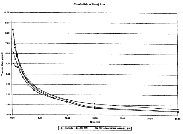
cm wicking height for representative distribution layers of the invention.
FIGURE 22 is a graph illustrating the effect of wicking height on transfer
capacity
rate for representative distribution layers of the invention.
In summary, the layer of the invention effectively distributes acquired liquid
to an
associated storage layer. The effective distribution allows for the full
utilization of the
absorbent capacity of the storage layer. In performing its distribution
function, the layer
avoids the problem of leakage of a personal care absorbent product resulting
from the
product's inability to fully and rapidly take up liquid discharged into the
product. In
-24-
CA 02428100 2003-05-08
WO 02/45760 PCT/USO1/47549
performing its distribution function, the layer effectively distributes liquid
to an
associated storage layer remote from the site of liquid insult thereby
avoiding the problem
of leakage resulting from liquid saturation of a storage core in the vicinity
of liquid insult.
Absorbent products having relatively thin and narrow designs are particularly
susceptible
to leakage and benefit the greatest from the advantages of the distribution
layer of the
invention. Again, through effective distribution of acquired liquid, the layer
provides for
the utilization of an associated storage layer's full absorbent capacity
thereby avoiding
excessive bulkiness and discomfort that result from a locally saturated
storage layer.
Furthermore, because the layer effectively transfers acquired liquid to an
associated
storage layer, the distribution layer of the invention has the advantageous
property of
being able to acquire, distribute, and ultimately transfer liquid acquired
from successive
insults. Because the distribution layer of the invention advantageous provides
rapid
liquid uptake, distribution, and release to an associated storage layer, both
initially and on
successive liquid insults, the layer is particularly well suited for
incorporation into
personal care absorbent products, such as infant diapers, training pants, and
incontinence
products, to provide improved absorbent products.
While the preferred embodiment of the invention has been illustrated and
described, it will be appreciated that various changes can be made therein
without
departing from the spirit and scope of the invention.
-25-